
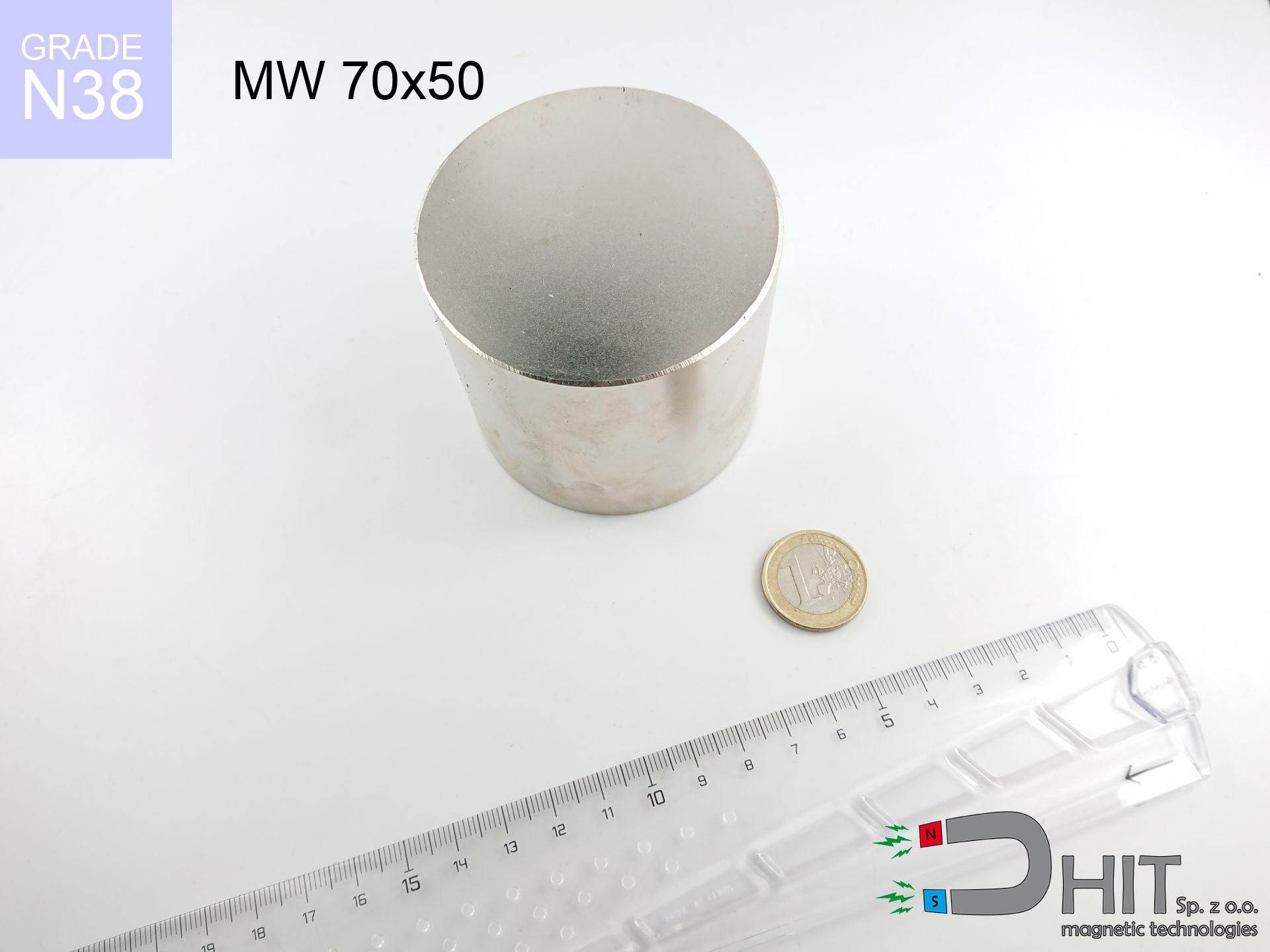
MW 70x50 / N38 - cylindrical magnet
cylindrical magnet
Catalog no 010496
GTIN/EAN: 5906301811145
Diameter Ø
70 mm [±0,1 mm]
Height
50 mm [±0,1 mm]
Weight
1443.17 g
Magnetization Direction
↑ axial
Load capacity
168.21 kg / 1650.14 N
Magnetic Induction
507.83 mT / 5078 Gs
Coating
[NiCuNi] Nickel
516.60 ZŁ with VAT / pcs + price for transport
420.00 ZŁ net + 23% VAT / pcs
bulk discounts:
Need more?
Call us now
+48 888 99 98 98
otherwise get in touch through
contact form
the contact section.
Lifting power and structure of magnets can be analyzed using our
modular calculator.
Same-day processing for orders placed before 14:00.
Technical details - MW 70x50 / N38 - cylindrical magnet
Specification / characteristics - MW 70x50 / N38 - cylindrical magnet
| properties | values |
|---|---|
| Cat. no. | 010496 |
| GTIN/EAN | 5906301811145 |
| Production/Distribution | Dhit sp. z o.o. |
| Country of origin | Poland / China / Germany |
| Customs code | 85059029 |
| Diameter Ø | 70 mm [±0,1 mm] |
| Height | 50 mm [±0,1 mm] |
| Weight | 1443.17 g |
| Magnetization Direction | ↑ axial |
| Load capacity ~ ? | 168.21 kg / 1650.14 N |
| Magnetic Induction ~ ? | 507.83 mT / 5078 Gs |
| Coating | [NiCuNi] Nickel |
| Manufacturing Tolerance | ±0.1 mm |
Magnetic properties of material N38
| properties | values | units |
|---|---|---|
| remenance Br [min. - max.] ? | 12.2-12.6 | kGs |
| remenance Br [min. - max.] ? | 1220-1260 | mT |
| coercivity bHc ? | 10.8-11.5 | kOe |
| coercivity bHc ? | 860-915 | kA/m |
| actual internal force iHc | ≥ 12 | kOe |
| actual internal force iHc | ≥ 955 | kA/m |
| energy density [min. - max.] ? | 36-38 | BH max MGOe |
| energy density [min. - max.] ? | 287-303 | BH max KJ/m |
| max. temperature ? | ≤ 80 | °C |
Physical properties of sintered neodymium magnets Nd2Fe14B at 20°C
| properties | values | units |
|---|---|---|
| Vickers hardness | ≥550 | Hv |
| Density | ≥7.4 | g/cm3 |
| Curie Temperature TC | 312 - 380 | °C |
| Curie Temperature TF | 593 - 716 | °F |
| Specific resistance | 150 | μΩ⋅cm |
| Bending strength | 250 | MPa |
| Compressive strength | 1000~1100 | MPa |
| Thermal expansion parallel (∥) to orientation (M) | (3-4) x 10-6 | °C-1 |
| Thermal expansion perpendicular (⊥) to orientation (M) | -(1-3) x 10-6 | °C-1 |
| Young's modulus | 1.7 x 10⁴ | kg/mm² |
Technical simulation of the magnet - data
The following data constitute the result of a engineering simulation. Results are based on models for the class Nd2Fe14B. Real-world conditions may deviate from the simulation results. Treat these calculations as a reference point for designers.
Table 1: Static pull force (force vs gap) - interaction chart
MW 70x50 / N38
| Distance (mm) | Induction (Gauss) / mT | Pull Force (kg/lbs/g/N) | Risk Status |
|---|---|---|---|
| 0 mm |
5078 Gs
507.8 mT
|
168.21 kg / 370.84 lbs
168210.0 g / 1650.1 N
|
crushing |
| 1 mm |
4935 Gs
493.5 mT
|
158.88 kg / 350.26 lbs
158876.4 g / 1558.6 N
|
crushing |
| 2 mm |
4790 Gs
479.0 mT
|
149.67 kg / 329.96 lbs
149666.1 g / 1468.2 N
|
crushing |
| 3 mm |
4644 Gs
464.4 mT
|
140.71 kg / 310.21 lbs
140708.8 g / 1380.4 N
|
crushing |
| 5 mm |
4354 Gs
435.4 mT
|
123.67 kg / 272.64 lbs
123667.4 g / 1213.2 N
|
crushing |
| 10 mm |
3652 Gs
365.2 mT
|
87.02 kg / 191.84 lbs
87016.1 g / 853.6 N
|
crushing |
| 15 mm |
3017 Gs
301.7 mT
|
59.37 kg / 130.88 lbs
59366.6 g / 582.4 N
|
crushing |
| 20 mm |
2469 Gs
246.9 mT
|
39.78 kg / 87.70 lbs
39781.3 g / 390.3 N
|
crushing |
| 30 mm |
1645 Gs
164.5 mT
|
17.66 kg / 38.93 lbs
17659.3 g / 173.2 N
|
crushing |
| 50 mm |
773 Gs
77.3 mT
|
3.89 kg / 8.59 lbs
3895.0 g / 38.2 N
|
warning |
Table 2: Slippage hold (wall)
MW 70x50 / N38
| Distance (mm) | Friction coefficient | Pull Force (kg/lbs/g/N) |
|---|---|---|
| 0 mm | Stal (~0.2) |
33.64 kg / 74.17 lbs
33642.0 g / 330.0 N
|
| 1 mm | Stal (~0.2) |
31.78 kg / 70.05 lbs
31776.0 g / 311.7 N
|
| 2 mm | Stal (~0.2) |
29.93 kg / 65.99 lbs
29934.0 g / 293.7 N
|
| 3 mm | Stal (~0.2) |
28.14 kg / 62.04 lbs
28142.0 g / 276.1 N
|
| 5 mm | Stal (~0.2) |
24.73 kg / 54.53 lbs
24734.0 g / 242.6 N
|
| 10 mm | Stal (~0.2) |
17.40 kg / 38.37 lbs
17404.0 g / 170.7 N
|
| 15 mm | Stal (~0.2) |
11.87 kg / 26.18 lbs
11874.0 g / 116.5 N
|
| 20 mm | Stal (~0.2) |
7.96 kg / 17.54 lbs
7956.0 g / 78.0 N
|
| 30 mm | Stal (~0.2) |
3.53 kg / 7.79 lbs
3532.0 g / 34.6 N
|
| 50 mm | Stal (~0.2) |
0.78 kg / 1.72 lbs
778.0 g / 7.6 N
|
Table 3: Vertical assembly (sliding) - vertical pull
MW 70x50 / N38
| Surface type | Friction coefficient / % Mocy | Max load (kg/lbs/g/N) |
|---|---|---|
| Raw steel |
µ = 0.3
30% Nominalnej Siły
|
50.46 kg / 111.25 lbs
50463.0 g / 495.0 N
|
| Painted steel (standard) |
µ = 0.2
20% Nominalnej Siły
|
33.64 kg / 74.17 lbs
33642.0 g / 330.0 N
|
| Oily/slippery steel |
µ = 0.1
10% Nominalnej Siły
|
16.82 kg / 37.08 lbs
16821.0 g / 165.0 N
|
| Magnet with anti-slip rubber |
µ = 0.5
50% Nominalnej Siły
|
84.11 kg / 185.42 lbs
84105.0 g / 825.1 N
|
Table 4: Steel thickness (saturation) - sheet metal selection
MW 70x50 / N38
| Steel thickness (mm) | % power | Real pull force (kg/lbs/g/N) |
|---|---|---|
| 0.5 mm |
|
5.61 kg / 12.36 lbs
5607.0 g / 55.0 N
|
| 1 mm |
|
14.02 kg / 30.90 lbs
14017.5 g / 137.5 N
|
| 2 mm |
|
28.03 kg / 61.81 lbs
28035.0 g / 275.0 N
|
| 3 mm |
|
42.05 kg / 92.71 lbs
42052.5 g / 412.5 N
|
| 5 mm |
|
70.09 kg / 154.52 lbs
70087.5 g / 687.6 N
|
| 10 mm |
|
140.18 kg / 309.03 lbs
140175.0 g / 1375.1 N
|
| 11 mm |
|
154.19 kg / 339.94 lbs
154192.5 g / 1512.6 N
|
| 12 mm |
|
168.21 kg / 370.84 lbs
168210.0 g / 1650.1 N
|
Table 5: Thermal stability (stability) - thermal limit
MW 70x50 / N38
| Ambient temp. (°C) | Power loss | Remaining pull (kg/lbs/g/N) | Status |
|---|---|---|---|
| 20 °C | 0.0% |
168.21 kg / 370.84 lbs
168210.0 g / 1650.1 N
|
OK |
| 40 °C | -2.2% |
164.51 kg / 362.68 lbs
164509.4 g / 1613.8 N
|
OK |
| 60 °C | -4.4% |
160.81 kg / 354.52 lbs
160808.8 g / 1577.5 N
|
OK |
| 80 °C | -6.6% |
157.11 kg / 346.36 lbs
157108.1 g / 1541.2 N
|
|
| 100 °C | -28.8% |
119.77 kg / 264.04 lbs
119765.5 g / 1174.9 N
|
Table 6: Two magnets (repulsion) - forces in the system
MW 70x50 / N38
| Gap (mm) | Attraction (kg/lbs) (N-S) | Sliding Force (kg/lbs/g/N) | Repulsion (kg/lbs) (N-N) |
|---|---|---|---|
| 0 mm |
611.75 kg / 1348.67 lbs
5 850 Gs
|
91.76 kg / 202.30 lbs
91762 g / 900.2 N
|
N/A |
| 1 mm |
594.86 kg / 1311.43 lbs
10 014 Gs
|
89.23 kg / 196.72 lbs
89229 g / 875.3 N
|
535.37 kg / 1180.29 lbs
~0 Gs
|
| 2 mm |
577.80 kg / 1273.84 lbs
9 870 Gs
|
86.67 kg / 191.08 lbs
86670 g / 850.2 N
|
520.02 kg / 1146.45 lbs
~0 Gs
|
| 3 mm |
560.95 kg / 1236.68 lbs
9 725 Gs
|
84.14 kg / 185.50 lbs
84142 g / 825.4 N
|
504.85 kg / 1113.01 lbs
~0 Gs
|
| 5 mm |
527.90 kg / 1163.81 lbs
9 434 Gs
|
79.18 kg / 174.57 lbs
79184 g / 776.8 N
|
475.11 kg / 1047.43 lbs
~0 Gs
|
| 10 mm |
449.75 kg / 991.54 lbs
8 708 Gs
|
67.46 kg / 148.73 lbs
67463 g / 661.8 N
|
404.78 kg / 892.38 lbs
~0 Gs
|
| 20 mm |
316.46 kg / 697.68 lbs
7 304 Gs
|
47.47 kg / 104.65 lbs
47469 g / 465.7 N
|
284.81 kg / 627.91 lbs
~0 Gs
|
| 50 mm |
96.30 kg / 212.30 lbs
4 029 Gs
|
14.44 kg / 31.85 lbs
14445 g / 141.7 N
|
86.67 kg / 191.07 lbs
~0 Gs
|
| 60 mm |
64.22 kg / 141.59 lbs
3 291 Gs
|
9.63 kg / 21.24 lbs
9634 g / 94.5 N
|
57.80 kg / 127.43 lbs
~0 Gs
|
| 70 mm |
43.17 kg / 95.18 lbs
2 698 Gs
|
6.48 kg / 14.28 lbs
6476 g / 63.5 N
|
38.86 kg / 85.66 lbs
~0 Gs
|
| 80 mm |
29.36 kg / 64.73 lbs
2 225 Gs
|
4.40 kg / 9.71 lbs
4404 g / 43.2 N
|
26.43 kg / 58.26 lbs
~0 Gs
|
| 90 mm |
20.25 kg / 44.63 lbs
1 847 Gs
|
3.04 kg / 6.69 lbs
3037 g / 29.8 N
|
18.22 kg / 40.17 lbs
~0 Gs
|
| 100 mm |
14.17 kg / 31.23 lbs
1 545 Gs
|
2.12 kg / 4.68 lbs
2125 g / 20.8 N
|
12.75 kg / 28.11 lbs
~0 Gs
|
Table 7: Safety (HSE) (implants) - warnings
MW 70x50 / N38
| Object / Device | Limit (Gauss) / mT | Safe distance |
|---|---|---|
| Pacemaker | 5 Gs (0.5 mT) | 40.0 cm |
| Hearing aid | 10 Gs (1.0 mT) | 31.5 cm |
| Timepiece | 20 Gs (2.0 mT) | 24.5 cm |
| Mobile device | 40 Gs (4.0 mT) | 19.0 cm |
| Remote | 50 Gs (5.0 mT) | 17.5 cm |
| Payment card | 400 Gs (40.0 mT) | 7.5 cm |
| HDD hard drive | 600 Gs (60.0 mT) | 6.0 cm |
Table 8: Collisions (kinetic energy) - warning
MW 70x50 / N38
| Start from (mm) | Speed (km/h) | Energy (J) | Predicted outcome |
|---|---|---|---|
| 10 mm |
13.97 km/h
(3.88 m/s)
|
10.87 J | |
| 30 mm |
20.06 km/h
(5.57 m/s)
|
22.40 J | |
| 50 mm |
24.70 km/h
(6.86 m/s)
|
33.96 J | |
| 100 mm |
34.46 km/h
(9.57 m/s)
|
66.12 J |
Table 9: Corrosion resistance
MW 70x50 / N38
| Technical parameter | Value / Description |
|---|---|
| Coating type | [NiCuNi] Nickel |
| Layer structure | Nickel - Copper - Nickel |
| Layer thickness | 10-20 µm |
| Salt spray test (SST) ? | 24 h |
| Recommended environment | Indoors only (dry) |
Table 10: Construction data (Pc)
MW 70x50 / N38
| Parameter | Value | SI Unit / Description |
|---|---|---|
| Magnetic Flux | 197 145 Mx | 1971.5 µWb |
| Pc Coefficient | 0.74 | High (Stable) |
Table 11: Submerged application
MW 70x50 / N38
| Environment | Effective steel pull | Effect |
|---|---|---|
| Air (land) | 168.21 kg | Standard |
| Water (riverbed) |
192.60 kg
(+24.39 kg buoyancy gain)
|
+14.5% |
1. Vertical hold
*Warning: On a vertical surface, the magnet retains merely ~20% of its nominal pull.
2. Plate thickness effect
*Thin metal sheet (e.g. 0.5mm PC case) severely weakens the holding force.
3. Heat tolerance
*For N38 grade, the safety limit is 80°C.
4. Demagnetization curve and operating point (B-H)
chart generated for the permeance coefficient Pc (Permeance Coefficient) = 0.74
This simulation demonstrates the magnetic stability of the selected magnet under specific geometric conditions. The solid red line represents the demagnetization curve (material potential), while the dashed blue line is the load line based on the magnet's geometry. The Pc (Permeance Coefficient), also known as the load line slope, is a dimensionless value that describes the relationship between the magnet's shape and its magnetic stability. The intersection of these two lines (the black dot) is the operating point — it determines the actual magnetic flux density generated by the magnet in this specific configuration. A higher Pc value means the magnet is more 'slender' (tall relative to its area), resulting in a higher operating point and better resistance to irreversible demagnetization caused by external fields or temperature. A value of 0.42 is relatively low (typical for flat magnets), meaning the operating point is closer to the 'knee' of the curve — caution is advised when operating at temperatures near the maximum limit to avoid strength loss.
Chemical composition
| iron (Fe) | 64% – 68% |
| neodymium (Nd) | 29% – 32% |
| boron (B) | 1.1% – 1.2% |
| dysprosium (Dy) | 0.5% – 2.0% |
| coating (Ni-Cu-Ni) | < 0.05% |
Sustainability
| recyclability (EoL) | 100% |
| recycled raw materials | ~10% (pre-cons) |
| carbon footprint | low / zredukowany |
| waste code (EWC) | 16 02 16 |
Check out also deals

![BM 550x180x70 [4x M8] - magnetic beam](https://cdn3.dhit.pl/graphics/products/bm-550x180x70-4x-m8-nic.jpg "BM 550x180x70 [4x M8] - magnetic beam")

![SM 32x300 [2xM8] / N42 - magnetic separator](https://cdn3.dhit.pl/graphics/products/sm-32x300-2xm8-pel.jpg "SM 32x300 [2xM8] / N42 - magnetic separator")
Strengths and weaknesses of rare earth magnets.
Benefits
- They virtually do not lose power, because even after ten years the decline in efficiency is only ~1% (according to literature),
- They retain their magnetic properties even under close interference source,
- In other words, due to the shiny surface of nickel, the element is aesthetically pleasing,
- Magnets are characterized by very high magnetic induction on the surface,
- Neodymium magnets are characterized by extremely high magnetic induction on the magnet surface and can function (depending on the shape) even at a temperature of 230°C or more...
- Thanks to the ability of precise forming and adaptation to specialized needs, neodymium magnets can be produced in a variety of geometric configurations, which expands the range of possible applications,
- Key role in innovative solutions – they serve a role in hard drives, electric drive systems, advanced medical instruments, and multitasking production systems.
- Thanks to concentrated force, small magnets offer high operating force, in miniature format,
Disadvantages
- Susceptibility to cracking is one of their disadvantages. Upon intense impact they can break. We advise keeping them in a strong case, which not only protects them against impacts but also increases their durability
- Neodymium magnets lose force when exposed to high temperatures. After reaching 80°C, many of them experience permanent weakening of strength (a factor is the shape and dimensions of the magnet). We offer magnets specially adapted to work at temperatures up to 230°C marked [AH], which are extremely resistant to heat
- Due to the susceptibility of magnets to corrosion in a humid environment, we recommend using waterproof magnets made of rubber, plastic or other material stable to moisture, in case of application outdoors
- We recommend a housing - magnetic mechanism, due to difficulties in creating threads inside the magnet and complicated shapes.
- Health risk related to microscopic parts of magnets can be dangerous, when accidentally swallowed, which becomes key in the aspect of protecting the youngest. It is also worth noting that small elements of these products can disrupt the diagnostic process medical when they are in the body.
- High unit price – neodymium magnets have a higher price than other types of magnets (e.g. ferrite), which can limit application in large quantities
Pull force analysis
Maximum lifting capacity of the magnet – what contributes to it?
- using a sheet made of low-carbon steel, acting as a circuit closing element
- with a cross-section no less than 10 mm
- with a surface free of scratches
- under conditions of ideal adhesion (surface-to-surface)
- for force acting at a right angle (pull-off, not shear)
- in neutral thermal conditions
Lifting capacity in real conditions – factors
- Distance (between the magnet and the metal), since even a very small clearance (e.g. 0.5 mm) leads to a drastic drop in lifting capacity by up to 50% (this also applies to paint, rust or debris).
- Direction of force – maximum parameter is obtained only during perpendicular pulling. The shear force of the magnet along the surface is usually several times lower (approx. 1/5 of the lifting capacity).
- Metal thickness – the thinner the sheet, the weaker the hold. Part of the magnetic field penetrates through instead of converting into lifting capacity.
- Material type – the best choice is high-permeability steel. Hardened steels may attract less.
- Surface structure – the smoother and more polished the surface, the larger the contact zone and stronger the hold. Roughness acts like micro-gaps.
- Heat – NdFeB sinters have a negative temperature coefficient. At higher temperatures they lose power, and at low temperatures they can be stronger (up to a certain limit).
Lifting capacity testing was carried out on plates with a smooth surface of optimal thickness, under a perpendicular pulling force, in contrast under shearing force the lifting capacity is smaller. In addition, even a minimal clearance between the magnet and the plate decreases the load capacity.
Safe handling of neodymium magnets
Shattering risk
Despite the nickel coating, neodymium is delicate and not impact-resistant. Avoid impacts, as the magnet may crumble into hazardous fragments.
Keep away from children
Product intended for adults. Tiny parts pose a choking risk, leading to serious injuries. Store away from kids and pets.
Serious injuries
Pinching hazard: The pulling power is so immense that it can cause hematomas, pinching, and broken bones. Protective gloves are recommended.
ICD Warning
Individuals with a pacemaker must keep an large gap from magnets. The magnetism can disrupt the functioning of the life-saving device.
Fire warning
Powder generated during cutting of magnets is flammable. Do not drill into magnets without proper cooling and knowledge.
Demagnetization risk
Standard neodymium magnets (N-type) undergo demagnetization when the temperature goes above 80°C. The loss of strength is permanent.
Respect the power
Before starting, check safety instructions. Uncontrolled attraction can break the magnet or injure your hand. Be predictive.
Metal Allergy
Nickel alert: The Ni-Cu-Ni coating consists of nickel. If skin irritation happens, cease working with magnets and wear gloves.
Cards and drives
Do not bring magnets close to a wallet, computer, or screen. The magnetic field can permanently damage these devices and erase data from cards.
Threat to navigation
GPS units and mobile phones are extremely susceptible to magnetic fields. Close proximity with a strong magnet can ruin the sensors in your phone.
Tabela kosztu i czasu dostawy
Płatność przed wysyłką:

GLS kurier
Przesyłka będzie u Ciebie za 2-3 dni
14.99 ZŁ

InPost Paczkomaty 24/7
Przesyłka będzie u Ciebie za 1-2 dni
12.30 ZŁ
Płatność przy odbiorze (pobranie):
GLS kurier
Przesyłka będzie u Ciebie za 1-2 dni
23.00 ZŁ
Rate the product
Your rating