
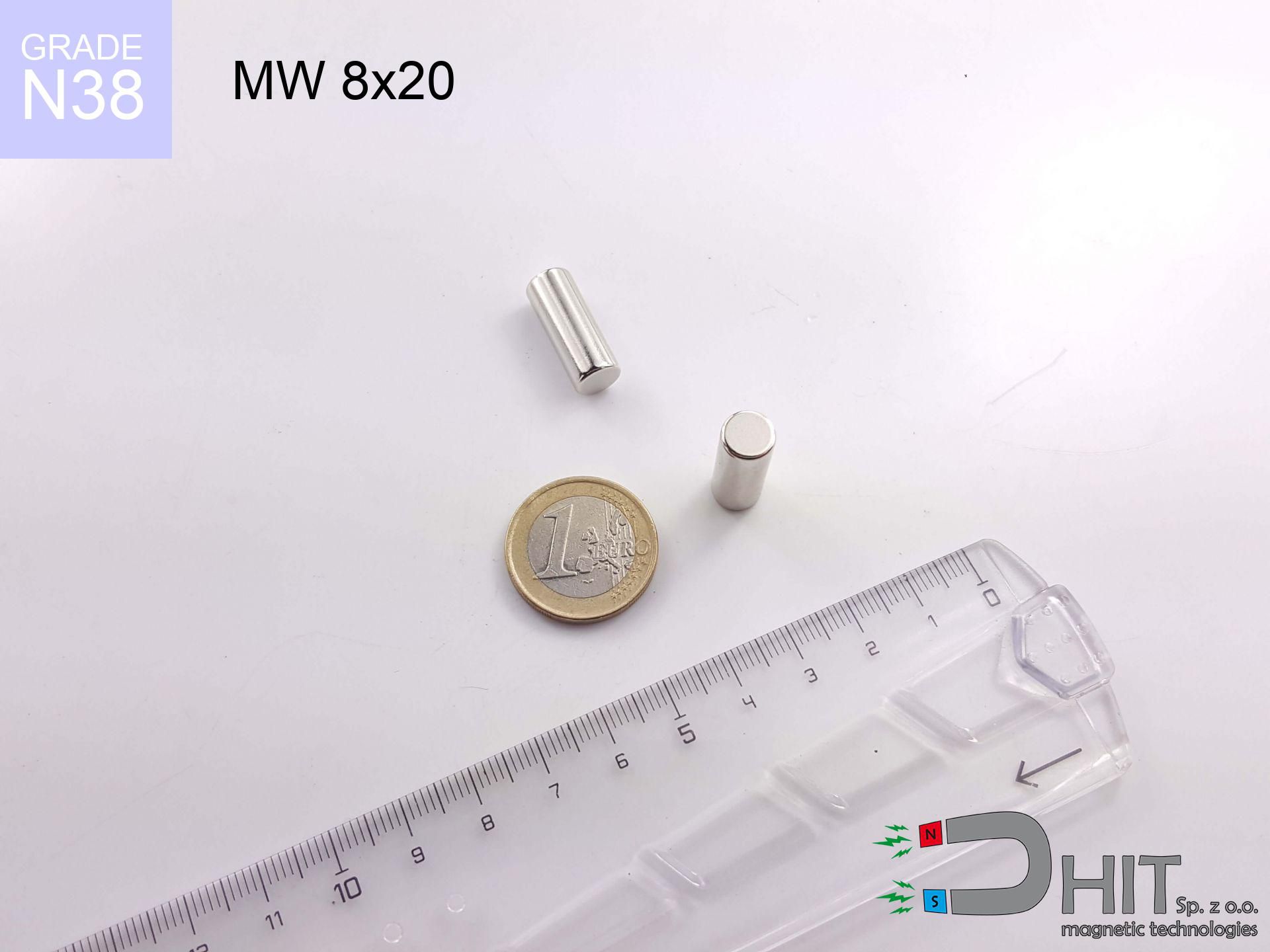
MW 8x20 / N38 - cylindrical magnet
cylindrical magnet
Catalog no 010475
GTIN/EAN: 5906301811138
Diameter Ø
8 mm [±0,1 mm]
Height
20 mm [±0,1 mm]
Weight
7.54 g
Magnetization Direction
→ diametrical
Load capacity
1.30 kg / 12.75 N
Magnetic Induction
607.01 mT / 6070 Gs
Coating
[NiCuNi] Nickel
4.60 ZŁ with VAT / pcs + price for transport
3.74 ZŁ net + 23% VAT / pcs
bulk discounts:
Need more?
Contact us by phone
+48 22 499 98 98
or send us a note using
our online form
the contact section.
Strength along with shape of neodymium magnets can be analyzed using our
online calculation tool.
Orders submitted before 14:00 will be dispatched today!
Product card - MW 8x20 / N38 - cylindrical magnet
Specification / characteristics - MW 8x20 / N38 - cylindrical magnet
| properties | values |
|---|---|
| Cat. no. | 010475 |
| GTIN/EAN | 5906301811138 |
| Production/Distribution | Dhit sp. z o.o. |
| Country of origin | Poland / China / Germany |
| Customs code | 85059029 |
| Diameter Ø | 8 mm [±0,1 mm] |
| Height | 20 mm [±0,1 mm] |
| Weight | 7.54 g |
| Magnetization Direction | → diametrical |
| Load capacity ~ ? | 1.30 kg / 12.75 N |
| Magnetic Induction ~ ? | 607.01 mT / 6070 Gs |
| Coating | [NiCuNi] Nickel |
| Manufacturing Tolerance | ±0.1 mm |
Magnetic properties of material N38
| properties | values | units |
|---|---|---|
| remenance Br [min. - max.] ? | 12.2-12.6 | kGs |
| remenance Br [min. - max.] ? | 1220-1260 | mT |
| coercivity bHc ? | 10.8-11.5 | kOe |
| coercivity bHc ? | 860-915 | kA/m |
| actual internal force iHc | ≥ 12 | kOe |
| actual internal force iHc | ≥ 955 | kA/m |
| energy density [min. - max.] ? | 36-38 | BH max MGOe |
| energy density [min. - max.] ? | 287-303 | BH max KJ/m |
| max. temperature ? | ≤ 80 | °C |
Physical properties of sintered neodymium magnets Nd2Fe14B at 20°C
| properties | values | units |
|---|---|---|
| Vickers hardness | ≥550 | Hv |
| Density | ≥7.4 | g/cm3 |
| Curie Temperature TC | 312 - 380 | °C |
| Curie Temperature TF | 593 - 716 | °F |
| Specific resistance | 150 | μΩ⋅cm |
| Bending strength | 250 | MPa |
| Compressive strength | 1000~1100 | MPa |
| Thermal expansion parallel (∥) to orientation (M) | (3-4) x 10-6 | °C-1 |
| Thermal expansion perpendicular (⊥) to orientation (M) | -(1-3) x 10-6 | °C-1 |
| Young's modulus | 1.7 x 10⁴ | kg/mm² |
Physical analysis of the product - technical parameters
The following data constitute the outcome of a engineering analysis. Values were calculated on models for the material Nd2Fe14B. Actual parameters may differ from theoretical values. Please consider these calculations as a preliminary roadmap during assembly planning.
Table 1: Static force (pull vs gap) - power drop
MW 8x20 / N38
| Distance (mm) | Induction (Gauss) / mT | Pull Force (kg/lbs/g/N) | Risk Status |
|---|---|---|---|
| 0 mm |
6064 Gs
606.4 mT
|
1.30 kg / 2.87 LBS
1300.0 g / 12.8 N
|
low risk |
| 1 mm |
4587 Gs
458.7 mT
|
0.74 kg / 1.64 LBS
743.7 g / 7.3 N
|
low risk |
| 2 mm |
3327 Gs
332.7 mT
|
0.39 kg / 0.86 LBS
391.4 g / 3.8 N
|
low risk |
| 3 mm |
2388 Gs
238.8 mT
|
0.20 kg / 0.44 LBS
201.6 g / 2.0 N
|
low risk |
| 5 mm |
1281 Gs
128.1 mT
|
0.06 kg / 0.13 LBS
58.0 g / 0.6 N
|
low risk |
| 10 mm |
389 Gs
38.9 mT
|
0.01 kg / 0.01 LBS
5.4 g / 0.1 N
|
low risk |
| 15 mm |
169 Gs
16.9 mT
|
0.00 kg / 0.00 LBS
1.0 g / 0.0 N
|
low risk |
| 20 mm |
90 Gs
9.0 mT
|
0.00 kg / 0.00 LBS
0.3 g / 0.0 N
|
low risk |
| 30 mm |
35 Gs
3.5 mT
|
0.00 kg / 0.00 LBS
0.0 g / 0.0 N
|
low risk |
| 50 mm |
10 Gs
1.0 mT
|
0.00 kg / 0.00 LBS
0.0 g / 0.0 N
|
low risk |
Table 2: Sliding force (vertical surface)
MW 8x20 / N38
| Distance (mm) | Friction coefficient | Pull Force (kg/lbs/g/N) |
|---|---|---|
| 0 mm | Stal (~0.2) |
0.26 kg / 0.57 LBS
260.0 g / 2.6 N
|
| 1 mm | Stal (~0.2) |
0.15 kg / 0.33 LBS
148.0 g / 1.5 N
|
| 2 mm | Stal (~0.2) |
0.08 kg / 0.17 LBS
78.0 g / 0.8 N
|
| 3 mm | Stal (~0.2) |
0.04 kg / 0.09 LBS
40.0 g / 0.4 N
|
| 5 mm | Stal (~0.2) |
0.01 kg / 0.03 LBS
12.0 g / 0.1 N
|
| 10 mm | Stal (~0.2) |
0.00 kg / 0.00 LBS
2.0 g / 0.0 N
|
| 15 mm | Stal (~0.2) |
0.00 kg / 0.00 LBS
0.0 g / 0.0 N
|
| 20 mm | Stal (~0.2) |
0.00 kg / 0.00 LBS
0.0 g / 0.0 N
|
| 30 mm | Stal (~0.2) |
0.00 kg / 0.00 LBS
0.0 g / 0.0 N
|
| 50 mm | Stal (~0.2) |
0.00 kg / 0.00 LBS
0.0 g / 0.0 N
|
Table 3: Vertical assembly (sliding) - behavior on slippery surfaces
MW 8x20 / N38
| Surface type | Friction coefficient / % Mocy | Max load (kg/lbs/g/N) |
|---|---|---|
| Raw steel |
µ = 0.3
30% Nominalnej Siły
|
0.39 kg / 0.86 LBS
390.0 g / 3.8 N
|
| Painted steel (standard) |
µ = 0.2
20% Nominalnej Siły
|
0.26 kg / 0.57 LBS
260.0 g / 2.6 N
|
| Oily/slippery steel |
µ = 0.1
10% Nominalnej Siły
|
0.13 kg / 0.29 LBS
130.0 g / 1.3 N
|
| Magnet with anti-slip rubber |
µ = 0.5
50% Nominalnej Siły
|
0.65 kg / 1.43 LBS
650.0 g / 6.4 N
|
Table 4: Material efficiency (substrate influence) - power losses
MW 8x20 / N38
| Steel thickness (mm) | % power | Real pull force (kg/lbs/g/N) |
|---|---|---|
| 0.5 mm |
|
0.13 kg / 0.29 LBS
130.0 g / 1.3 N
|
| 1 mm |
|
0.33 kg / 0.72 LBS
325.0 g / 3.2 N
|
| 2 mm |
|
0.65 kg / 1.43 LBS
650.0 g / 6.4 N
|
| 3 mm |
|
0.98 kg / 2.15 LBS
975.0 g / 9.6 N
|
| 5 mm |
|
1.30 kg / 2.87 LBS
1300.0 g / 12.8 N
|
| 10 mm |
|
1.30 kg / 2.87 LBS
1300.0 g / 12.8 N
|
| 11 mm |
|
1.30 kg / 2.87 LBS
1300.0 g / 12.8 N
|
| 12 mm |
|
1.30 kg / 2.87 LBS
1300.0 g / 12.8 N
|
Table 5: Working in heat (material behavior) - thermal limit
MW 8x20 / N38
| Ambient temp. (°C) | Power loss | Remaining pull (kg/lbs/g/N) | Status |
|---|---|---|---|
| 20 °C | 0.0% |
1.30 kg / 2.87 LBS
1300.0 g / 12.8 N
|
OK |
| 40 °C | -2.2% |
1.27 kg / 2.80 LBS
1271.4 g / 12.5 N
|
OK |
| 60 °C | -4.4% |
1.24 kg / 2.74 LBS
1242.8 g / 12.2 N
|
OK |
| 80 °C | -6.6% |
1.21 kg / 2.68 LBS
1214.2 g / 11.9 N
|
|
| 100 °C | -28.8% |
0.93 kg / 2.04 LBS
925.6 g / 9.1 N
|
Table 6: Two magnets (attraction) - field collision
MW 8x20 / N38
| Gap (mm) | Attraction (kg/lbs) (N-S) | Lateral Force (kg/lbs/g/N) | Repulsion (kg/lbs) (N-N) |
|---|---|---|---|
| 0 mm |
11.40 kg / 25.12 LBS
6 154 Gs
|
1.71 kg / 3.77 LBS
1709 g / 16.8 N
|
N/A |
| 1 mm |
8.76 kg / 19.31 LBS
10 632 Gs
|
1.31 kg / 2.90 LBS
1314 g / 12.9 N
|
7.88 kg / 17.38 LBS
~0 Gs
|
| 2 mm |
6.52 kg / 14.37 LBS
9 174 Gs
|
0.98 kg / 2.16 LBS
978 g / 9.6 N
|
5.87 kg / 12.94 LBS
~0 Gs
|
| 3 mm |
4.76 kg / 10.49 LBS
7 837 Gs
|
0.71 kg / 1.57 LBS
714 g / 7.0 N
|
4.28 kg / 9.44 LBS
~0 Gs
|
| 5 mm |
2.46 kg / 5.43 LBS
5 637 Gs
|
0.37 kg / 0.81 LBS
369 g / 3.6 N
|
2.22 kg / 4.88 LBS
~0 Gs
|
| 10 mm |
0.51 kg / 1.12 LBS
2 561 Gs
|
0.08 kg / 0.17 LBS
76 g / 0.7 N
|
0.46 kg / 1.01 LBS
~0 Gs
|
| 20 mm |
0.05 kg / 0.10 LBS
778 Gs
|
0.01 kg / 0.02 LBS
7 g / 0.1 N
|
0.04 kg / 0.09 LBS
~0 Gs
|
| 50 mm |
0.00 kg / 0.00 LBS
107 Gs
|
0.00 kg / 0.00 LBS
0 g / 0.0 N
|
0.00 kg / 0.00 LBS
~0 Gs
|
| 60 mm |
0.00 kg / 0.00 LBS
69 Gs
|
0.00 kg / 0.00 LBS
0 g / 0.0 N
|
0.00 kg / 0.00 LBS
~0 Gs
|
| 70 mm |
0.00 kg / 0.00 LBS
48 Gs
|
0.00 kg / 0.00 LBS
0 g / 0.0 N
|
0.00 kg / 0.00 LBS
~0 Gs
|
| 80 mm |
0.00 kg / 0.00 LBS
34 Gs
|
0.00 kg / 0.00 LBS
0 g / 0.0 N
|
0.00 kg / 0.00 LBS
~0 Gs
|
| 90 mm |
0.00 kg / 0.00 LBS
25 Gs
|
0.00 kg / 0.00 LBS
0 g / 0.0 N
|
0.00 kg / 0.00 LBS
~0 Gs
|
| 100 mm |
0.00 kg / 0.00 LBS
19 Gs
|
0.00 kg / 0.00 LBS
0 g / 0.0 N
|
0.00 kg / 0.00 LBS
~0 Gs
|
Table 7: Safety (HSE) (implants) - precautionary measures
MW 8x20 / N38
| Object / Device | Limit (Gauss) / mT | Safe distance |
|---|---|---|
| Pacemaker | 5 Gs (0.5 mT) | 6.5 cm |
| Hearing aid | 10 Gs (1.0 mT) | 5.0 cm |
| Timepiece | 20 Gs (2.0 mT) | 4.0 cm |
| Mobile device | 40 Gs (4.0 mT) | 3.0 cm |
| Remote | 50 Gs (5.0 mT) | 3.0 cm |
| Payment card | 400 Gs (40.0 mT) | 1.0 cm |
| HDD hard drive | 600 Gs (60.0 mT) | 1.0 cm |
Table 8: Dynamics (kinetic energy) - warning
MW 8x20 / N38
| Start from (mm) | Speed (km/h) | Energy (J) | Predicted outcome |
|---|---|---|---|
| 10 mm |
13.28 km/h
(3.69 m/s)
|
0.05 J | |
| 30 mm |
22.94 km/h
(6.37 m/s)
|
0.15 J | |
| 50 mm |
29.61 km/h
(8.23 m/s)
|
0.26 J | |
| 100 mm |
41.88 km/h
(11.63 m/s)
|
0.51 J |
Table 9: Coating parameters (durability)
MW 8x20 / N38
| Technical parameter | Value / Description |
|---|---|
| Coating type | [NiCuNi] Nickel |
| Layer structure | Nickel - Copper - Nickel |
| Layer thickness | 10-20 µm |
| Salt spray test (SST) ? | 24 h |
| Recommended environment | Indoors only (dry) |
Table 10: Construction data (Pc)
MW 8x20 / N38
| Parameter | Value | SI Unit / Description |
|---|---|---|
| Magnetic Flux | 3 457 Mx | 34.6 µWb |
| Pc Coefficient | 1.31 | High (Stable) |
Table 11: Submerged application
MW 8x20 / N38
| Environment | Effective steel pull | Effect |
|---|---|---|
| Air (land) | 1.30 kg | Standard |
| Water (riverbed) |
1.49 kg
(+0.19 kg buoyancy gain)
|
+14.5% |
1. Shear force
*Note: On a vertical wall, the magnet holds only approx. 20-30% of its perpendicular strength.
2. Steel thickness impact
*Thin metal sheet (e.g. 0.5mm PC case) severely reduces the holding force.
3. Power loss vs temp
*For N38 grade, the safety limit is 80°C.
4. Demagnetization curve and operating point (B-H)
chart generated for the permeance coefficient Pc (Permeance Coefficient) = 1.31
The chart above illustrates the magnetic characteristics of the material within the second quadrant of the hysteresis loop. The solid red line represents the demagnetization curve (material potential), while the dashed blue line is the load line based on the magnet's geometry. The Pc (Permeance Coefficient), also known as the load line slope, is a dimensionless value that describes the relationship between the magnet's shape and its magnetic stability. The intersection of these two lines (the black dot) is the operating point — it determines the actual magnetic flux density generated by the magnet in this specific configuration. A higher Pc value means the magnet is more 'slender' (tall relative to its area), resulting in a higher operating point and better resistance to irreversible demagnetization caused by external fields or temperature. A value of 0.42 is relatively low (typical for flat magnets), meaning the operating point is closer to the 'knee' of the curve — caution is advised when operating at temperatures near the maximum limit to avoid strength loss.
Material specification
| iron (Fe) | 64% – 68% |
| neodymium (Nd) | 29% – 32% |
| boron (B) | 1.1% – 1.2% |
| dysprosium (Dy) | 0.5% – 2.0% |
| coating (Ni-Cu-Ni) | < 0.05% |
Environmental data
| recyclability (EoL) | 100% |
| recycled raw materials | ~10% (pre-cons) |
| carbon footprint | low / zredukowany |
| waste code (EWC) | 16 02 16 |
Other deals


![UI 45x13x6 [Z323] / N38 - badge holder](https://cdn3.dhit.pl/graphics/products/ui45x13x6-z323-fap.jpg "UI 45x13x6 [Z323] / N38 - badge holder")
Advantages as well as disadvantages of Nd2Fe14B magnets.
Advantages
- They do not lose power, even after approximately 10 years – the drop in power is only ~1% (theoretically),
- They possess excellent resistance to weakening of magnetic properties due to external magnetic sources,
- In other words, due to the glossy finish of silver, the element becomes visually attractive,
- Magnets possess exceptionally strong magnetic induction on the surface,
- Neodymium magnets are characterized by extremely high magnetic induction on the magnet surface and can work (depending on the form) even at a temperature of 230°C or more...
- Possibility of precise machining and optimizing to defined requirements,
- Significant place in innovative solutions – they find application in HDD drives, drive modules, precision medical tools, and multitasking production systems.
- Compactness – despite small sizes they provide effective action, making them ideal for precision applications
Cons
- Susceptibility to cracking is one of their disadvantages. Upon intense impact they can fracture. We recommend keeping them in a special holder, which not only protects them against impacts but also increases their durability
- Neodymium magnets decrease their power under the influence of heating. As soon as 80°C is exceeded, many of them start losing their power. Therefore, we recommend our special magnets marked [AH], which maintain durability even at temperatures up to 230°C
- They rust in a humid environment - during use outdoors we advise using waterproof magnets e.g. in rubber, plastic
- Due to limitations in producing threads and complicated shapes in magnets, we propose using casing - magnetic mount.
- Possible danger resulting from small fragments of magnets can be dangerous, if swallowed, which gains importance in the aspect of protecting the youngest. It is also worth noting that tiny parts of these magnets are able to complicate diagnosis medical in case of swallowing.
- Higher cost of purchase is one of the disadvantages compared to ceramic magnets, especially in budget applications
Holding force characteristics
Maximum magnetic pulling force – what contributes to it?
- using a sheet made of low-carbon steel, serving as a circuit closing element
- possessing a thickness of minimum 10 mm to ensure full flux closure
- with a plane cleaned and smooth
- with direct contact (without impurities)
- for force acting at a right angle (pull-off, not shear)
- in neutral thermal conditions
Determinants of practical lifting force of a magnet
- Clearance – existence of any layer (paint, tape, air) interrupts the magnetic circuit, which reduces capacity rapidly (even by 50% at 0.5 mm).
- Direction of force – maximum parameter is reached only during perpendicular pulling. The resistance to sliding of the magnet along the surface is standardly many times lower (approx. 1/5 of the lifting capacity).
- Wall thickness – the thinner the sheet, the weaker the hold. Magnetic flux penetrates through instead of converting into lifting capacity.
- Chemical composition of the base – low-carbon steel gives the best results. Alloy admixtures decrease magnetic permeability and holding force.
- Surface condition – smooth surfaces guarantee perfect abutment, which increases force. Rough surfaces weaken the grip.
- Temperature – heating the magnet causes a temporary drop of force. Check the maximum operating temperature for a given model.
Lifting capacity testing was performed on a smooth plate of suitable thickness, under perpendicular forces, whereas under attempts to slide the magnet the lifting capacity is smaller. Moreover, even a slight gap between the magnet and the plate reduces the load capacity.
Safe handling of neodymium magnets
Nickel allergy
Medical facts indicate that nickel (the usual finish) is a potent allergen. For allergy sufferers, refrain from direct skin contact or choose encased magnets.
Handling rules
Before starting, read the rules. Uncontrolled attraction can destroy the magnet or hurt your hand. Be predictive.
Product not for children
Only for adults. Small elements pose a choking risk, causing serious injuries. Keep out of reach of kids and pets.
Physical harm
Protect your hands. Two large magnets will join immediately with a force of several hundred kilograms, destroying everything in their path. Exercise extreme caution!
Combustion hazard
Powder produced during grinding of magnets is self-igniting. Do not drill into magnets without proper cooling and knowledge.
Phone sensors
Navigation devices and smartphones are extremely sensitive to magnetic fields. Direct contact with a powerful NdFeB magnet can permanently damage the internal compass in your phone.
Shattering risk
Neodymium magnets are ceramic materials, which means they are prone to chipping. Collision of two magnets leads to them cracking into small pieces.
Thermal limits
Watch the temperature. Heating the magnet above 80 degrees Celsius will permanently weaken its magnetic structure and pulling force.
Data carriers
Avoid bringing magnets near a wallet, laptop, or TV. The magnetic field can irreversibly ruin these devices and erase data from cards.
Medical implants
Individuals with a pacemaker must maintain an large gap from magnets. The magnetism can interfere with the functioning of the implant.
Tabela kosztu i czasu dostawy
Płatność przed wysyłką:

GLS kurier
Przesyłka będzie u Ciebie za 2-3 dni
14.99 ZŁ

InPost Paczkomaty 24/7
Przesyłka będzie u Ciebie za 1-2 dni
12.30 ZŁ
Płatność przy odbiorze (pobranie):
GLS kurier
Przesyłka będzie u Ciebie za 1-2 dni
23.00 ZŁ
Rate the product
Your rating