
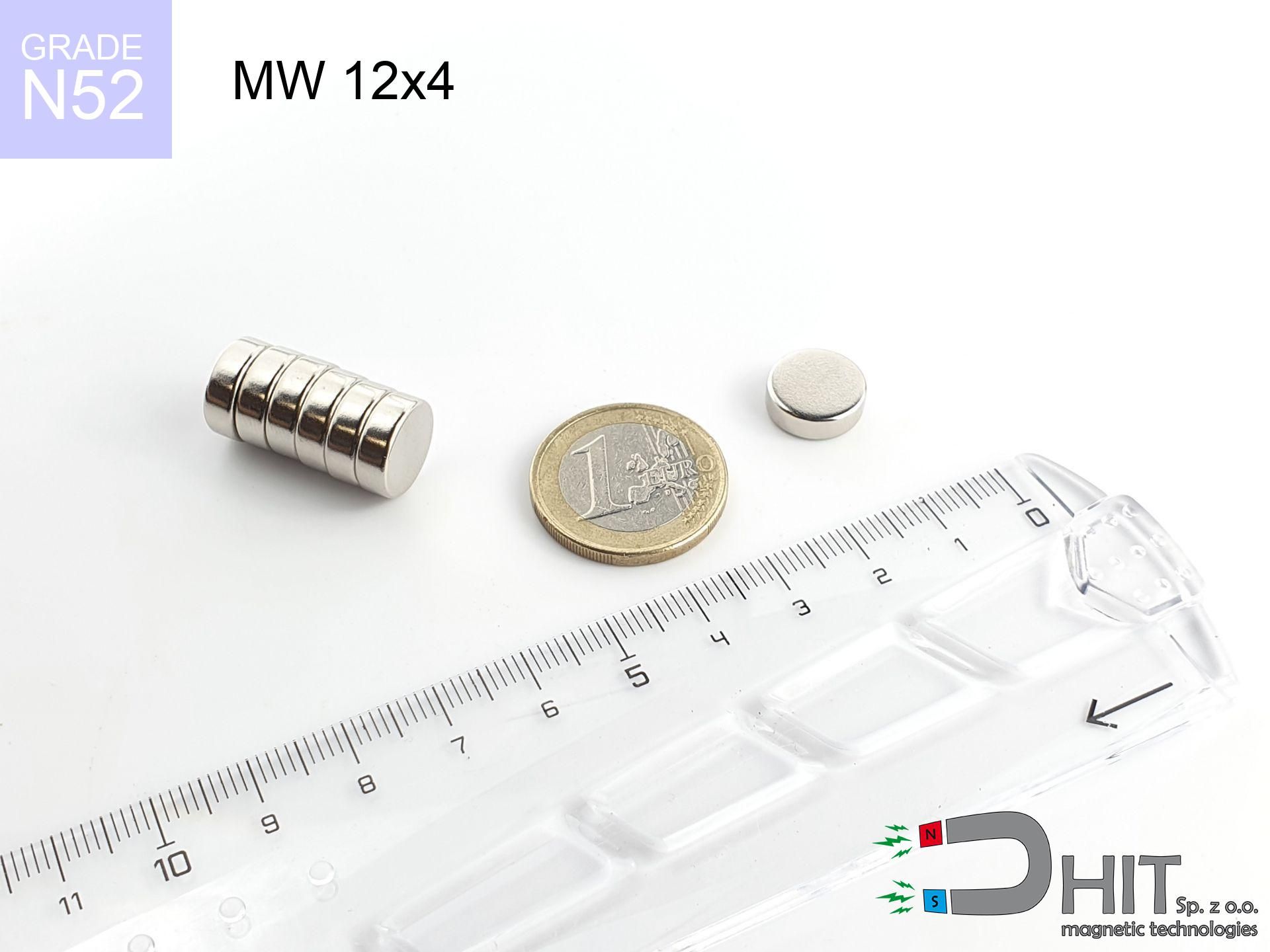
MW 12x4 / N52 - cylindrical magnet
cylindrical magnet
Catalog no 010500
GTIN/EAN: 5906301814962
Diameter Ø
12 mm [±0,1 mm]
Height
4 mm [±0,1 mm]
Weight
3.39 g
Magnetization Direction
↑ axial
Load capacity
4.68 kg / 45.89 N
Magnetic Induction
400.45 mT / 4005 Gs
Coating
[NiCuNi] Nickel
2.18 ZŁ with VAT / pcs + price for transport
1.770 ZŁ net + 23% VAT / pcs
bulk discounts:
Need more?
Call us now
+48 888 99 98 98
if you prefer send us a note by means of
our online form
the contact section.
Parameters as well as appearance of a neodymium magnet can be reviewed with our
force calculator.
Orders submitted before 14:00 will be dispatched today!
Technical specification - MW 12x4 / N52 - cylindrical magnet
Specification / characteristics - MW 12x4 / N52 - cylindrical magnet
| properties | values |
|---|---|
| Cat. no. | 010500 |
| GTIN/EAN | 5906301814962 |
| Production/Distribution | Dhit sp. z o.o. |
| Country of origin | Poland / China / Germany |
| Customs code | 85059029 |
| Diameter Ø | 12 mm [±0,1 mm] |
| Height | 4 mm [±0,1 mm] |
| Weight | 3.39 g |
| Magnetization Direction | ↑ axial |
| Load capacity ~ ? | 4.68 kg / 45.89 N |
| Magnetic Induction ~ ? | 400.45 mT / 4005 Gs |
| Coating | [NiCuNi] Nickel |
| Manufacturing Tolerance | ±0.1 mm |
Magnetic properties of material N52
| properties | values | units |
|---|---|---|
| remenance Br [min. - max.] ? | 14.2-14.7 | kGs |
| remenance Br [min. - max.] ? | 1420-1470 | mT |
| coercivity bHc ? | 10.8-12.5 | kOe |
| coercivity bHc ? | 860-995 | kA/m |
| actual internal force iHc | ≥ 12 | kOe |
| actual internal force iHc | ≥ 955 | kA/m |
| energy density [min. - max.] ? | 48-53 | BH max MGOe |
| energy density [min. - max.] ? | 380-422 | BH max KJ/m |
| max. temperature ? | ≤ 80 | °C |
Physical properties of sintered neodymium magnets Nd2Fe14B at 20°C
| properties | values | units |
|---|---|---|
| Vickers hardness | ≥550 | Hv |
| Density | ≥7.4 | g/cm3 |
| Curie Temperature TC | 312 - 380 | °C |
| Curie Temperature TF | 593 - 716 | °F |
| Specific resistance | 150 | μΩ⋅cm |
| Bending strength | 250 | MPa |
| Compressive strength | 1000~1100 | MPa |
| Thermal expansion parallel (∥) to orientation (M) | (3-4) x 10-6 | °C-1 |
| Thermal expansion perpendicular (⊥) to orientation (M) | -(1-3) x 10-6 | °C-1 |
| Young's modulus | 1.7 x 10⁴ | kg/mm² |
Technical modeling of the assembly - data
These data constitute the result of a engineering calculation. Values were calculated on algorithms for the material Nd2Fe14B. Real-world parameters may differ. Please consider these data as a reference point during assembly planning.
Table 1: Static force (pull vs gap) - power drop
MW 12x4 / N52
| Distance (mm) | Induction (Gauss) / mT | Pull Force (kg/lbs/g/N) | Risk Status |
|---|---|---|---|
| 0 mm |
4003 Gs
400.3 mT
|
4.68 kg / 10.32 pounds
4680.0 g / 45.9 N
|
medium risk |
| 1 mm |
3438 Gs
343.8 mT
|
3.45 kg / 7.61 pounds
3451.9 g / 33.9 N
|
medium risk |
| 2 mm |
2824 Gs
282.4 mT
|
2.33 kg / 5.14 pounds
2329.8 g / 22.9 N
|
medium risk |
| 3 mm |
2255 Gs
225.5 mT
|
1.48 kg / 3.27 pounds
1484.8 g / 14.6 N
|
weak grip |
| 5 mm |
1386 Gs
138.6 mT
|
0.56 kg / 1.24 pounds
561.3 g / 5.5 N
|
weak grip |
| 10 mm |
445 Gs
44.5 mT
|
0.06 kg / 0.13 pounds
58.0 g / 0.6 N
|
weak grip |
| 15 mm |
181 Gs
18.1 mT
|
0.01 kg / 0.02 pounds
9.6 g / 0.1 N
|
weak grip |
| 20 mm |
89 Gs
8.9 mT
|
0.00 kg / 0.01 pounds
2.3 g / 0.0 N
|
weak grip |
| 30 mm |
30 Gs
3.0 mT
|
0.00 kg / 0.00 pounds
0.3 g / 0.0 N
|
weak grip |
| 50 mm |
7 Gs
0.7 mT
|
0.00 kg / 0.00 pounds
0.0 g / 0.0 N
|
weak grip |
Table 2: Slippage force (wall)
MW 12x4 / N52
| Distance (mm) | Friction coefficient | Pull Force (kg/lbs/g/N) |
|---|---|---|
| 0 mm | Stal (~0.2) |
0.94 kg / 2.06 pounds
936.0 g / 9.2 N
|
| 1 mm | Stal (~0.2) |
0.69 kg / 1.52 pounds
690.0 g / 6.8 N
|
| 2 mm | Stal (~0.2) |
0.47 kg / 1.03 pounds
466.0 g / 4.6 N
|
| 3 mm | Stal (~0.2) |
0.30 kg / 0.65 pounds
296.0 g / 2.9 N
|
| 5 mm | Stal (~0.2) |
0.11 kg / 0.25 pounds
112.0 g / 1.1 N
|
| 10 mm | Stal (~0.2) |
0.01 kg / 0.03 pounds
12.0 g / 0.1 N
|
| 15 mm | Stal (~0.2) |
0.00 kg / 0.00 pounds
2.0 g / 0.0 N
|
| 20 mm | Stal (~0.2) |
0.00 kg / 0.00 pounds
0.0 g / 0.0 N
|
| 30 mm | Stal (~0.2) |
0.00 kg / 0.00 pounds
0.0 g / 0.0 N
|
| 50 mm | Stal (~0.2) |
0.00 kg / 0.00 pounds
0.0 g / 0.0 N
|
Table 3: Wall mounting (shearing) - vertical pull
MW 12x4 / N52
| Surface type | Friction coefficient / % Mocy | Max load (kg/lbs/g/N) |
|---|---|---|
| Raw steel |
µ = 0.3
30% Nominalnej Siły
|
1.40 kg / 3.10 pounds
1404.0 g / 13.8 N
|
| Painted steel (standard) |
µ = 0.2
20% Nominalnej Siły
|
0.94 kg / 2.06 pounds
936.0 g / 9.2 N
|
| Oily/slippery steel |
µ = 0.1
10% Nominalnej Siły
|
0.47 kg / 1.03 pounds
468.0 g / 4.6 N
|
| Magnet with anti-slip rubber |
µ = 0.5
50% Nominalnej Siły
|
2.34 kg / 5.16 pounds
2340.0 g / 23.0 N
|
Table 4: Material efficiency (saturation) - sheet metal selection
MW 12x4 / N52
| Steel thickness (mm) | % power | Real pull force (kg/lbs/g/N) |
|---|---|---|
| 0.5 mm |
|
0.47 kg / 1.03 pounds
468.0 g / 4.6 N
|
| 1 mm |
|
1.17 kg / 2.58 pounds
1170.0 g / 11.5 N
|
| 2 mm |
|
2.34 kg / 5.16 pounds
2340.0 g / 23.0 N
|
| 3 mm |
|
3.51 kg / 7.74 pounds
3510.0 g / 34.4 N
|
| 5 mm |
|
4.68 kg / 10.32 pounds
4680.0 g / 45.9 N
|
| 10 mm |
|
4.68 kg / 10.32 pounds
4680.0 g / 45.9 N
|
| 11 mm |
|
4.68 kg / 10.32 pounds
4680.0 g / 45.9 N
|
| 12 mm |
|
4.68 kg / 10.32 pounds
4680.0 g / 45.9 N
|
Table 5: Working in heat (material behavior) - thermal limit
MW 12x4 / N52
| Ambient temp. (°C) | Power loss | Remaining pull (kg/lbs/g/N) | Status |
|---|---|---|---|
| 20 °C | 0.0% |
4.68 kg / 10.32 pounds
4680.0 g / 45.9 N
|
OK |
| 40 °C | -2.2% |
4.58 kg / 10.09 pounds
4577.0 g / 44.9 N
|
OK |
| 60 °C | -4.4% |
4.47 kg / 9.86 pounds
4474.1 g / 43.9 N
|
|
| 80 °C | -6.6% |
4.37 kg / 9.64 pounds
4371.1 g / 42.9 N
|
|
| 100 °C | -28.8% |
3.33 kg / 7.35 pounds
3332.2 g / 32.7 N
|
Table 6: Two magnets (attraction) - forces in the system
MW 12x4 / N52
| Gap (mm) | Attraction (kg/lbs) (N-S) | Shear Strength (kg/lbs/g/N) | Repulsion (kg/lbs) (N-N) |
|---|---|---|---|
| 0 mm |
11.17 kg / 24.63 pounds
5 771 Gs
|
1.68 kg / 3.69 pounds
1676 g / 16.4 N
|
N/A |
| 1 mm |
9.73 kg / 21.44 pounds
7 470 Gs
|
1.46 kg / 3.22 pounds
1459 g / 14.3 N
|
8.75 kg / 19.30 pounds
~0 Gs
|
| 2 mm |
8.24 kg / 18.16 pounds
6 875 Gs
|
1.24 kg / 2.72 pounds
1236 g / 12.1 N
|
7.42 kg / 16.35 pounds
~0 Gs
|
| 3 mm |
6.83 kg / 15.06 pounds
6 260 Gs
|
1.02 kg / 2.26 pounds
1024 g / 10.1 N
|
6.15 kg / 13.55 pounds
~0 Gs
|
| 5 mm |
4.46 kg / 9.84 pounds
5 060 Gs
|
0.67 kg / 1.48 pounds
670 g / 6.6 N
|
4.02 kg / 8.86 pounds
~0 Gs
|
| 10 mm |
1.34 kg / 2.95 pounds
2 772 Gs
|
0.20 kg / 0.44 pounds
201 g / 2.0 N
|
1.21 kg / 2.66 pounds
~0 Gs
|
| 20 mm |
0.14 kg / 0.30 pounds
891 Gs
|
0.02 kg / 0.05 pounds
21 g / 0.2 N
|
0.12 kg / 0.27 pounds
~0 Gs
|
| 50 mm |
0.00 kg / 0.00 pounds
99 Gs
|
0.00 kg / 0.00 pounds
0 g / 0.0 N
|
0.00 kg / 0.00 pounds
~0 Gs
|
| 60 mm |
0.00 kg / 0.00 pounds
61 Gs
|
0.00 kg / 0.00 pounds
0 g / 0.0 N
|
0.00 kg / 0.00 pounds
~0 Gs
|
| 70 mm |
0.00 kg / 0.00 pounds
40 Gs
|
0.00 kg / 0.00 pounds
0 g / 0.0 N
|
0.00 kg / 0.00 pounds
~0 Gs
|
| 80 mm |
0.00 kg / 0.00 pounds
27 Gs
|
0.00 kg / 0.00 pounds
0 g / 0.0 N
|
0.00 kg / 0.00 pounds
~0 Gs
|
| 90 mm |
0.00 kg / 0.00 pounds
20 Gs
|
0.00 kg / 0.00 pounds
0 g / 0.0 N
|
0.00 kg / 0.00 pounds
~0 Gs
|
| 100 mm |
0.00 kg / 0.00 pounds
15 Gs
|
0.00 kg / 0.00 pounds
0 g / 0.0 N
|
0.00 kg / 0.00 pounds
~0 Gs
|
Table 7: Hazards (implants) - warnings
MW 12x4 / N52
| Object / Device | Limit (Gauss) / mT | Safe distance |
|---|---|---|
| Pacemaker | 5 Gs (0.5 mT) | 6.0 cm |
| Hearing aid | 10 Gs (1.0 mT) | 4.5 cm |
| Mechanical watch | 20 Gs (2.0 mT) | 3.5 cm |
| Phone / Smartphone | 40 Gs (4.0 mT) | 3.0 cm |
| Car key | 50 Gs (5.0 mT) | 2.5 cm |
| Payment card | 400 Gs (40.0 mT) | 1.5 cm |
| HDD hard drive | 600 Gs (60.0 mT) | 1.0 cm |
Table 8: Collisions (kinetic energy) - collision effects
MW 12x4 / N52
| Start from (mm) | Speed (km/h) | Energy (J) | Predicted outcome |
|---|---|---|---|
| 10 mm |
37.76 km/h
(10.49 m/s)
|
0.19 J | |
| 30 mm |
64.91 km/h
(18.03 m/s)
|
0.55 J | |
| 50 mm |
83.79 km/h
(23.27 m/s)
|
0.92 J | |
| 100 mm |
118.50 km/h
(32.92 m/s)
|
1.84 J |
Table 9: Anti-corrosion coating durability
MW 12x4 / N52
| Technical parameter | Value / Description |
|---|---|
| Coating type | [NiCuNi] Nickel |
| Layer structure | Nickel - Copper - Nickel |
| Layer thickness | 10-20 µm |
| Salt spray test (SST) ? | 24 h |
| Recommended environment | Indoors only (dry) |
Table 10: Construction data (Pc)
MW 12x4 / N52
| Parameter | Value | SI Unit / Description |
|---|---|---|
| Magnetic Flux | 4 794 Mx | 47.9 µWb |
| Pc Coefficient | 0.44 | Low (Flat) |
Table 11: Submerged application
MW 12x4 / N52
| Environment | Effective steel pull | Effect |
|---|---|---|
| Air (land) | 4.68 kg | Standard |
| Water (riverbed) |
5.36 kg
(+0.68 kg buoyancy gain)
|
+14.5% |
1. Shear force
*Note: On a vertical wall, the magnet retains only approx. 20-30% of its max power.
2. Steel thickness impact
*Thin metal sheet (e.g. 0.5mm PC case) drastically reduces the holding force.
3. Power loss vs temp
*For N38 grade, the critical limit is 80°C.
4. Demagnetization curve and operating point (B-H)
chart generated for the permeance coefficient Pc (Permeance Coefficient) = 0.44
This simulation demonstrates the magnetic stability of the selected magnet under specific geometric conditions. The solid red line represents the demagnetization curve (material potential), while the dashed blue line is the load line based on the magnet's geometry. The Pc (Permeance Coefficient), also known as the load line slope, is a dimensionless value that describes the relationship between the magnet's shape and its magnetic stability. The intersection of these two lines (the black dot) is the operating point — it determines the actual magnetic flux density generated by the magnet in this specific configuration. A higher Pc value means the magnet is more 'slender' (tall relative to its area), resulting in a higher operating point and better resistance to irreversible demagnetization caused by external fields or temperature. A value of 0.42 is relatively low (typical for flat magnets), meaning the operating point is closer to the 'knee' of the curve — caution is advised when operating at temperatures near the maximum limit to avoid strength loss.
Chemical composition
| iron (Fe) | 64% – 68% |
| neodymium (Nd) | 29% – 32% |
| boron (B) | 1.1% – 1.2% |
| dysprosium (Dy) | 0.5% – 2.0% |
| coating (Ni-Cu-Ni) | < 0.05% |
Sustainability
| recyclability (EoL) | 100% |
| recycled raw materials | ~10% (pre-cons) |
| carbon footprint | low / zredukowany |
| waste code (EWC) | 16 02 16 |
Other deals


Strengths and weaknesses of neodymium magnets.
Strengths
- They retain magnetic properties for around 10 years – the loss is just ~1% (based on simulations),
- They show high resistance to demagnetization induced by external magnetic fields,
- Thanks to the glossy finish, the plating of nickel, gold-plated, or silver-plated gives an clean appearance,
- Neodymium magnets generate maximum magnetic induction on a small surface, which allows for strong attraction,
- Due to their durability and thermal resistance, neodymium magnets can operate (depending on the shape) even at high temperatures reaching 230°C or more...
- Thanks to modularity in constructing and the capacity to adapt to complex applications,
- Universal use in innovative solutions – they are utilized in mass storage devices, motor assemblies, medical equipment, and modern systems.
- Compactness – despite small sizes they provide effective action, making them ideal for precision applications
Weaknesses
- At strong impacts they can break, therefore we recommend placing them in steel cases. A metal housing provides additional protection against damage, as well as increases the magnet's durability.
- We warn that neodymium magnets can reduce their strength at high temperatures. To prevent this, we suggest our specialized [AH] magnets, which work effectively even at 230°C.
- Magnets exposed to a humid environment can rust. Therefore during using outdoors, we recommend using water-impermeable magnets made of rubber, plastic or other material resistant to moisture
- We recommend a housing - magnetic mount, due to difficulties in realizing threads inside the magnet and complex shapes.
- Health risk related to microscopic parts of magnets pose a threat, when accidentally swallowed, which gains importance in the context of child health protection. Furthermore, small components of these magnets are able to complicate diagnosis medical when they are in the body.
- With mass production the cost of neodymium magnets can be a barrier,
Holding force characteristics
Breakaway strength of the magnet in ideal conditions – what contributes to it?
- with the application of a yoke made of special test steel, ensuring full magnetic saturation
- possessing a thickness of at least 10 mm to avoid saturation
- with an ideally smooth touching surface
- under conditions of no distance (metal-to-metal)
- under axial force vector (90-degree angle)
- in temp. approx. 20°C
Impact of factors on magnetic holding capacity in practice
- Distance (betwixt the magnet and the metal), as even a tiny clearance (e.g. 0.5 mm) results in a drastic drop in lifting capacity by up to 50% (this also applies to paint, rust or debris).
- Pull-off angle – remember that the magnet has greatest strength perpendicularly. Under shear forces, the capacity drops significantly, often to levels of 20-30% of the nominal value.
- Steel thickness – insufficiently thick sheet does not accept the full field, causing part of the flux to be wasted to the other side.
- Material composition – different alloys attracts identically. Alloy additives worsen the interaction with the magnet.
- Surface condition – ground elements ensure maximum contact, which improves force. Uneven metal reduce efficiency.
- Temperature – heating the magnet causes a temporary drop of force. It is worth remembering the maximum operating temperature for a given model.
Lifting capacity was determined with the use of a polished steel plate of optimal thickness (min. 20 mm), under perpendicular detachment force, however under shearing force the lifting capacity is smaller. In addition, even a small distance between the magnet’s surface and the plate decreases the load capacity.
Safe handling of neodymium magnets
Impact on smartphones
An intense magnetic field interferes with the functioning of compasses in phones and navigation systems. Do not bring magnets close to a device to prevent damaging the sensors.
Serious injuries
Large magnets can crush fingers in a fraction of a second. Never put your hand betwixt two attracting surfaces.
Powerful field
Use magnets with awareness. Their powerful strength can surprise even experienced users. Stay alert and respect their power.
Warning for heart patients
Warning for patients: Strong magnetic fields disrupt electronics. Maintain minimum 30 cm distance or request help to work with the magnets.
Material brittleness
Despite the nickel coating, neodymium is brittle and not impact-resistant. Avoid impacts, as the magnet may crumble into hazardous fragments.
Data carriers
Avoid bringing magnets near a wallet, computer, or screen. The magnetism can permanently damage these devices and wipe information from cards.
No play value
Neodymium magnets are not intended for children. Swallowing several magnets may result in them connecting inside the digestive tract, which constitutes a direct threat to life and necessitates immediate surgery.
Skin irritation risks
Some people have a sensitization to Ni, which is the standard coating for neodymium magnets. Frequent touching can result in a rash. We strongly advise use safety gloves.
Maximum temperature
Regular neodymium magnets (N-type) undergo demagnetization when the temperature exceeds 80°C. The loss of strength is permanent.
Flammability
Powder produced during cutting of magnets is flammable. Avoid drilling into magnets unless you are an expert.
Tabela kosztu i czasu dostawy
Płatność przed wysyłką:

GLS kurier
Przesyłka będzie u Ciebie za 2-3 dni
14.99 ZŁ

InPost Paczkomaty 24/7
Przesyłka będzie u Ciebie za 1-2 dni
12.30 ZŁ
Płatność przy odbiorze (pobranie):
GLS kurier
Przesyłka będzie u Ciebie za 1-2 dni
23.00 ZŁ
Rate the product
Your rating