
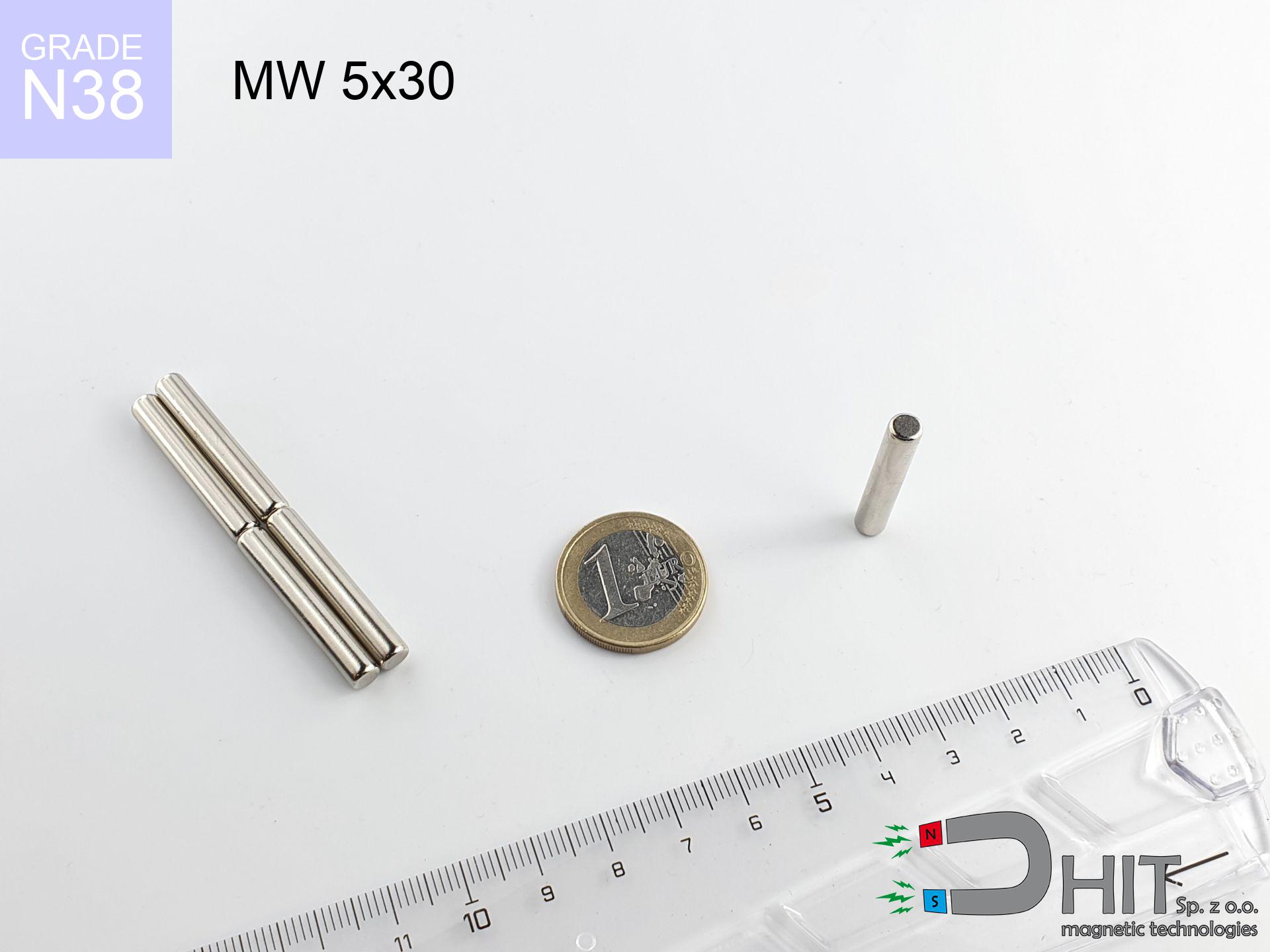
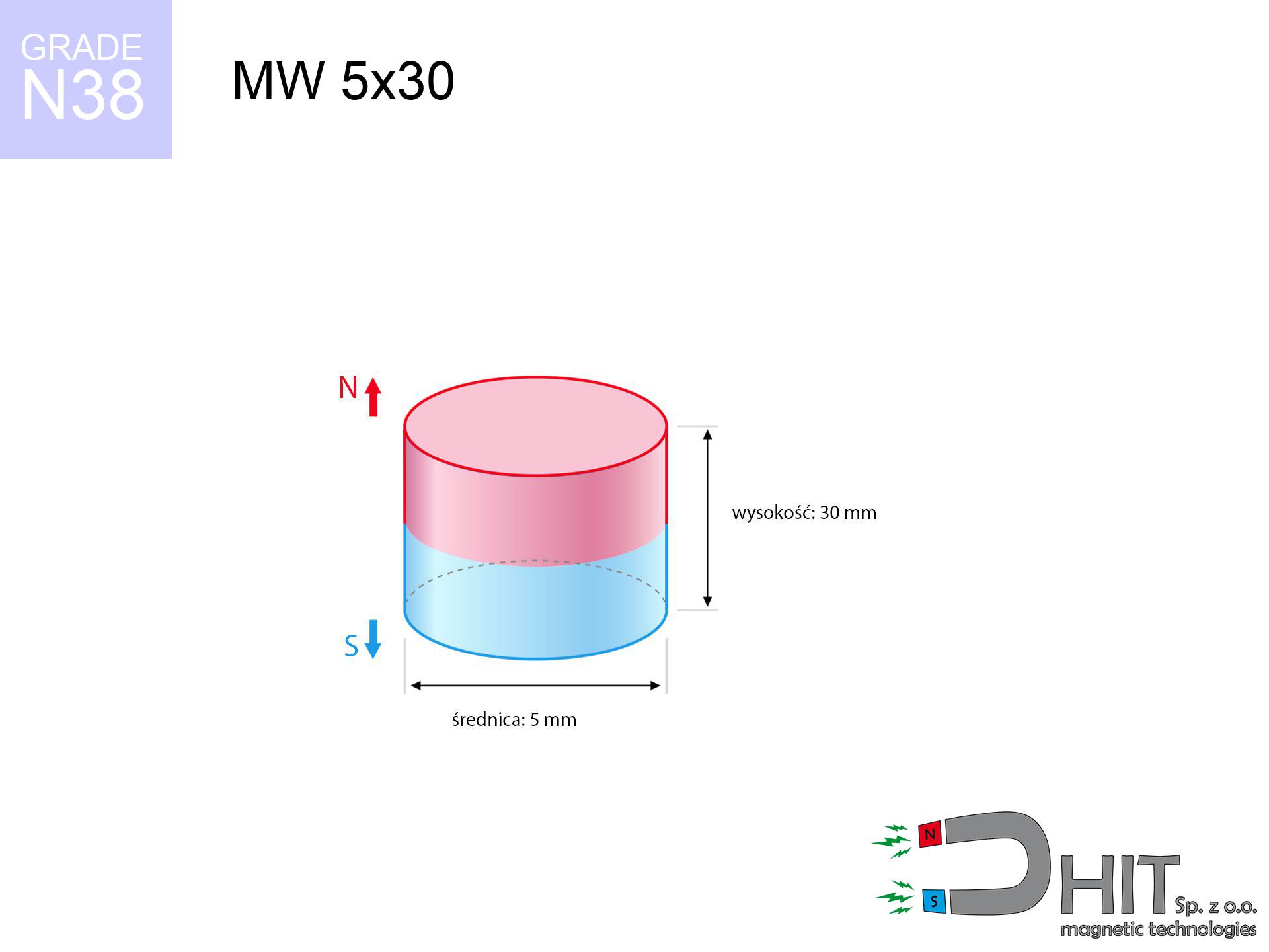
MW 5x30 / N38 - cylindrical magnet
cylindrical magnet
Catalog no 010088
GTIN/EAN: 5906301810872
- Diameter Ø
- 5 mm [±0,1 mm]
- Height
- 30 mm [±0,1 mm]
- Weight
- 4.42 g
- Magnetization Direction
- ↑ axial
- Coating
- [NiCuNi] Nickel
3.57 zł with VAT / pcs + price for transport
2.90 zł net + 23% VAT / pcs
bulk discounts:
Need more?Engineering report for this magnet
Full PDF analysis: pull and shear force, effect of distance, temperature and plate thickness, safety distances and the demagnetization curve.
Give us a call
+48 888 99 98 98
if you prefer send us a note via
form
our website.
Specifications as well as form of a magnet can be checked on our
online calculation tool.
Same-day shipping for orders placed before 14:00.
Technical parameters of the product - MW 5x30 / N38 - cylindrical magnet
Specification / characteristics - MW 5x30 / N38 - cylindrical magnet
| properties | values |
|---|---|
| Cat. no. | 010088 |
| GTIN/EAN | 5906301810872 |
| Production/Distribution | Dhit sp. z o.o. |
| Country of origin | Poland / China / Germany |
| Customs code | 85059029 |
| Diameter Ø | 5 mm [±0,1 mm] |
| Height | 30 mm [±0,1 mm] |
| Weight | 4.42 g |
| Magnetization Direction | ↑ axial |
| Load capacity ~ ? | 0.45 kg / 4.40 N |
| Magnetic Induction ~ ? | 616.32 mT / 6163 Gs |
| Coating | [NiCuNi] Nickel |
| Manufacturing Tolerance | ±0.1 mm |
Magnetic properties of material N38
| properties | values | units |
|---|---|---|
| remenance Br [min. - max.] ? | 12.2-12.6 | kGs |
| remenance Br [min. - max.] ? | 1220-1260 | mT |
| coercivity bHc ? | 10.8-11.5 | kOe |
| coercivity bHc ? | 860-915 | kA/m |
| actual internal force iHc | ≥ 12 | kOe |
| actual internal force iHc | ≥ 955 | kA/m |
| energy density [min. - max.] ? | 36-38 | BH max MGOe |
| energy density [min. - max.] ? | 287-303 | BH max KJ/m |
| max. temperature ? | ≤ 80 | °C |
Physical properties of sintered neodymium magnets Nd2Fe14B at 20°C
| properties | values | units |
|---|---|---|
| Vickers hardness | ≥550 | Hv |
| Density | ≥7.4 | g/cm3 |
| Curie Temperature TC | 312 - 380 | °C |
| Curie Temperature TF | 593 - 716 | °F |
| Specific resistance | 150 | μΩ⋅cm |
| Bending strength | 250 | MPa |
| Compressive strength | 1000~1100 | MPa |
| Thermal expansion parallel (∥) to orientation (M) | (3-4) x 10-6 | °C-1 |
| Thermal expansion perpendicular (⊥) to orientation (M) | -(1-3) x 10-6 | °C-1 |
| Young's modulus | 1.7 x 10⁴ | kg/mm² |
Physical modeling of the assembly - data
Presented data represent the direct effect of a mathematical analysis. Results were calculated on algorithms for the class Nd2Fe14B. Real-world conditions might slightly differ from theoretical values. Treat these calculations as a reference point for designers.
Table 1: Static force (force vs gap) - characteristics
MW 5x30 / N38
| Distance (mm) | Induction (Gauss) / mT | Pull Force (kg/lbs/g/N) | Risk Status |
|---|---|---|---|
| 0 mm |
6154 Gs
615.4 mT
|
0.45 kg / 0.99 lbs
450.0 g / 4.4 N
|
weak grip |
| 1 mm |
3877 Gs
387.7 mT
|
0.18 kg / 0.39 lbs
178.6 g / 1.8 N
|
weak grip |
| 2 mm |
2308 Gs
230.8 mT
|
0.06 kg / 0.14 lbs
63.3 g / 0.6 N
|
weak grip |
| 3 mm |
1419 Gs
141.9 mT
|
0.02 kg / 0.05 lbs
23.9 g / 0.2 N
|
weak grip |
| 5 mm |
639 Gs
63.9 mT
|
0.00 kg / 0.01 lbs
4.8 g / 0.0 N
|
weak grip |
| 10 mm |
173 Gs
17.3 mT
|
0.00 kg / 0.00 lbs
0.4 g / 0.0 N
|
weak grip |
| 15 mm |
75 Gs
7.5 mT
|
0.00 kg / 0.00 lbs
0.1 g / 0.0 N
|
weak grip |
| 20 mm |
40 Gs
4.0 mT
|
0.00 kg / 0.00 lbs
0.0 g / 0.0 N
|
weak grip |
| 30 mm |
16 Gs
1.6 mT
|
0.00 kg / 0.00 lbs
0.0 g / 0.0 N
|
weak grip |
| 50 mm |
5 Gs
0.5 mT
|
0.00 kg / 0.00 lbs
0.0 g / 0.0 N
|
weak grip |
Table 2: Vertical capacity (vertical surface)
MW 5x30 / N38
| Distance (mm) | Friction coefficient | Pull Force (kg/lbs/g/N) |
|---|---|---|
| 0 mm | Stal (~0.2) |
0.09 kg / 0.20 lbs
90.0 g / 0.9 N
|
| 1 mm | Stal (~0.2) |
0.04 kg / 0.08 lbs
36.0 g / 0.4 N
|
| 2 mm | Stal (~0.2) |
0.01 kg / 0.03 lbs
12.0 g / 0.1 N
|
| 3 mm | Stal (~0.2) |
0.00 kg / 0.01 lbs
4.0 g / 0.0 N
|
| 5 mm | Stal (~0.2) |
0.00 kg / 0.00 lbs
0.0 g / 0.0 N
|
| 10 mm | Stal (~0.2) |
0.00 kg / 0.00 lbs
0.0 g / 0.0 N
|
| 15 mm | Stal (~0.2) |
0.00 kg / 0.00 lbs
0.0 g / 0.0 N
|
| 20 mm | Stal (~0.2) |
0.00 kg / 0.00 lbs
0.0 g / 0.0 N
|
| 30 mm | Stal (~0.2) |
0.00 kg / 0.00 lbs
0.0 g / 0.0 N
|
| 50 mm | Stal (~0.2) |
0.00 kg / 0.00 lbs
0.0 g / 0.0 N
|
Table 3: Wall mounting (shearing) - behavior on slippery surfaces
MW 5x30 / N38
| Surface type | Friction coefficient / % Mocy | Max load (kg/lbs/g/N) |
|---|---|---|
| Raw steel |
µ = 0.3
30% Nominalnej Siły
|
0.14 kg / 0.30 lbs
135.0 g / 1.3 N
|
| Painted steel (standard) |
µ = 0.2
20% Nominalnej Siły
|
0.09 kg / 0.20 lbs
90.0 g / 0.9 N
|
| Oily/slippery steel |
µ = 0.1
10% Nominalnej Siły
|
0.05 kg / 0.10 lbs
45.0 g / 0.4 N
|
| Magnet with anti-slip rubber |
µ = 0.5
50% Nominalnej Siły
|
0.23 kg / 0.50 lbs
225.0 g / 2.2 N
|
Table 4: Material efficiency (saturation) - sheet metal selection
MW 5x30 / N38
| Steel thickness (mm) | % power | Real pull force (kg/lbs/g/N) |
|---|---|---|
| 0.5 mm |
|
0.05 kg / 0.10 lbs
45.0 g / 0.4 N
|
| 1 mm |
|
0.11 kg / 0.25 lbs
112.5 g / 1.1 N
|
| 2 mm |
|
0.23 kg / 0.50 lbs
225.0 g / 2.2 N
|
| 3 mm |
|
0.34 kg / 0.74 lbs
337.5 g / 3.3 N
|
| 5 mm |
|
0.45 kg / 0.99 lbs
450.0 g / 4.4 N
|
| 10 mm |
|
0.45 kg / 0.99 lbs
450.0 g / 4.4 N
|
| 11 mm |
|
0.45 kg / 0.99 lbs
450.0 g / 4.4 N
|
| 12 mm |
|
0.45 kg / 0.99 lbs
450.0 g / 4.4 N
|
Table 5: Working in heat (stability) - resistance threshold
MW 5x30 / N38
| Ambient temp. (°C) | Power loss | Remaining pull (kg/lbs/g/N) | Status |
|---|---|---|---|
| 20 °C | 0.0% |
0.45 kg / 0.99 lbs
450.0 g / 4.4 N
|
OK |
| 40 °C | -2.2% |
0.44 kg / 0.97 lbs
440.1 g / 4.3 N
|
OK |
| 60 °C | -4.4% |
0.43 kg / 0.95 lbs
430.2 g / 4.2 N
|
OK |
| 80 °C | -6.6% |
0.42 kg / 0.93 lbs
420.3 g / 4.1 N
|
|
| 100 °C | -28.8% |
0.32 kg / 0.71 lbs
320.4 g / 3.1 N
|
Table 6: Two magnets (repulsion) - field range
MW 5x30 / N38
| Gap (mm) | Attraction (kg/lbs) (N-S) | Sliding Force (kg/lbs/g/N) | Repulsion (kg/lbs) (N-N) |
|---|---|---|---|
| 0 mm |
4.58 kg / 10.11 lbs
6 170 Gs
|
0.69 kg / 1.52 lbs
688 g / 6.7 N
|
N/A |
| 1 mm |
2.98 kg / 6.57 lbs
9 927 Gs
|
0.45 kg / 0.99 lbs
447 g / 4.4 N
|
2.68 kg / 5.92 lbs
~0 Gs
|
| 2 mm |
1.82 kg / 4.01 lbs
7 755 Gs
|
0.27 kg / 0.60 lbs
273 g / 2.7 N
|
1.64 kg / 3.61 lbs
~0 Gs
|
| 3 mm |
1.08 kg / 2.39 lbs
5 981 Gs
|
0.16 kg / 0.36 lbs
162 g / 1.6 N
|
0.97 kg / 2.15 lbs
~0 Gs
|
| 5 mm |
0.39 kg / 0.86 lbs
3 595 Gs
|
0.06 kg / 0.13 lbs
59 g / 0.6 N
|
0.35 kg / 0.78 lbs
~0 Gs
|
| 10 mm |
0.05 kg / 0.11 lbs
1 278 Gs
|
0.01 kg / 0.02 lbs
7 g / 0.1 N
|
0.04 kg / 0.10 lbs
~0 Gs
|
| 20 mm |
0.00 kg / 0.01 lbs
346 Gs
|
0.00 kg / 0.00 lbs
1 g / 0.0 N
|
0.00 kg / 0.00 lbs
~0 Gs
|
| 50 mm |
0.00 kg / 0.00 lbs
49 Gs
|
0.00 kg / 0.00 lbs
0 g / 0.0 N
|
0.00 kg / 0.00 lbs
~0 Gs
|
| 60 mm |
0.00 kg / 0.00 lbs
32 Gs
|
0.00 kg / 0.00 lbs
0 g / 0.0 N
|
0.00 kg / 0.00 lbs
~0 Gs
|
| 70 mm |
0.00 kg / 0.00 lbs
22 Gs
|
0.00 kg / 0.00 lbs
0 g / 0.0 N
|
0.00 kg / 0.00 lbs
~0 Gs
|
| 80 mm |
0.00 kg / 0.00 lbs
16 Gs
|
0.00 kg / 0.00 lbs
0 g / 0.0 N
|
0.00 kg / 0.00 lbs
~0 Gs
|
| 90 mm |
0.00 kg / 0.00 lbs
12 Gs
|
0.00 kg / 0.00 lbs
0 g / 0.0 N
|
0.00 kg / 0.00 lbs
~0 Gs
|
| 100 mm |
0.00 kg / 0.00 lbs
9 Gs
|
0.00 kg / 0.00 lbs
0 g / 0.0 N
|
0.00 kg / 0.00 lbs
~0 Gs
|
Table 7: Safety (HSE) (implants) - warnings
MW 5x30 / N38
| Object / Device | Limit (Gauss) / mT | Safe distance |
|---|---|---|
| Pacemaker | 5 Gs (0.5 mT) | 5.0 cm |
| Hearing aid | 10 Gs (1.0 mT) | 4.0 cm |
| Timepiece | 20 Gs (2.0 mT) | 3.0 cm |
| Phone / Smartphone | 40 Gs (4.0 mT) | 2.5 cm |
| Car key | 50 Gs (5.0 mT) | 2.0 cm |
| Payment card | 400 Gs (40.0 mT) | 1.0 cm |
| HDD hard drive | 600 Gs (60.0 mT) | 1.0 cm |
Table 8: Collisions (cracking risk) - collision effects
MW 5x30 / N38
| Start from (mm) | Speed (km/h) | Energy (J) | Predicted outcome |
|---|---|---|---|
| 10 mm |
5.27 km/h
(1.46 m/s)
|
0.00 J | |
| 30 mm |
5.28 km/h
(1.47 m/s)
|
0.00 J | |
| 50 mm |
5.28 km/h
(1.47 m/s)
|
0.00 J | |
| 100 mm |
5.28 km/h
(1.47 m/s)
|
0.00 J |
Table 9: Anti-corrosion coating durability
MW 5x30 / N38
| Technical parameter | Value / Description |
|---|---|
| Coating type | [NiCuNi] Nickel |
| Layer structure | Nickel - Copper - Nickel |
| Layer thickness | 10-20 µm |
| Salt spray test (SST) ? | 24 h |
| Recommended environment | Indoors only (dry) |
Table 10: Construction data (Flux)
MW 5x30 / N38
| Parameter | Value | SI Unit / Description |
|---|---|---|
| Magnetic Flux | 1 468 Mx | 14.7 µWb |
| Pc Coefficient | 1.59 | High (Stable) |
Table 11: Submerged application
MW 5x30 / N38
| Environment | Effective steel pull | Effect |
|---|---|---|
| Air (land) | 0.45 kg | Standard |
| Water (riverbed) |
0.52 kg
(+0.07 kg buoyancy gain)
|
+14.5% |
1. Wall mount (shear)
*Caution: On a vertical wall, the magnet holds just approx. 20-30% of its max power.
2. Plate thickness effect
*Thin metal sheet (e.g. computer case) severely limits the holding force.
3. Temperature resistance
*For standard magnets, the max working temp is 80°C.
4. Demagnetization curve and operating point (B-H)
chart generated for the permeance coefficient Pc (Permeance Coefficient) = 1.59
The chart above illustrates the magnetic characteristics of the material within the second quadrant of the hysteresis loop. The solid red line represents the demagnetization curve (material potential), while the dashed blue line is the load line based on the magnet's geometry. The Pc (Permeance Coefficient), also known as the load line slope, is a dimensionless value that describes the relationship between the magnet's shape and its magnetic stability. The intersection of these two lines (the black dot) is the operating point — it determines the actual magnetic flux density generated by the magnet in this specific configuration. A higher Pc value means the magnet is more 'slender' (tall relative to its area), resulting in a higher operating point and better resistance to irreversible demagnetization caused by external fields or temperature. A value of 0.42 is relatively low (typical for flat magnets), meaning the operating point is closer to the 'knee' of the curve — caution is advised when operating at temperatures near the maximum limit to avoid strength loss.
Material specification
| iron (Fe) | 64% – 68% |
| neodymium (Nd) | 29% – 32% |
| boron (B) | 1.1% – 1.2% |
| dysprosium (Dy) | 0.5% – 2.0% |
| coating (Ni-Cu-Ni) | < 0.05% |
Ecology and recycling (GPSR)
| recyclability (EoL) | 100% |
| recycled raw materials | ~10% (pre-cons) |
| carbon footprint | low / zredukowany |
| waste code (EWC) | 16 02 16 |
Other offers


Pros as well as cons of Nd2Fe14B magnets.
Pros
- They do not lose magnetism, even during around ten years – the drop in power is only ~1% (according to tests),
- They possess excellent resistance to weakening of magnetic properties when exposed to opposing magnetic fields,
- In other words, due to the glossy layer of silver, the element becomes visually attractive,
- Neodymium magnets ensure maximum magnetic induction on a their surface, which increases force concentration,
- Neodymium magnets are characterized by very high magnetic induction on the magnet surface and can work (depending on the shape) even at a temperature of 230°C or more...
- Due to the potential of free molding and adaptation to specialized projects, NdFeB magnets can be created in a wide range of shapes and sizes, which amplifies use scope,
- Wide application in advanced technology sectors – they find application in hard drives, electric motors, medical devices, also multitasking production systems.
- Compactness – despite small sizes they provide effective action, making them ideal for precision applications
Disadvantages
- They are prone to damage upon too strong impacts. To avoid cracks, it is worth securing magnets using a steel holder. Such protection not only protects the magnet but also increases its resistance to damage
- Neodymium magnets lose their force under the influence of heating. As soon as 80°C is exceeded, many of them start losing their power. Therefore, we recommend our special magnets marked [AH], which maintain durability even at temperatures up to 230°C
- Magnets exposed to a humid environment can corrode. Therefore during using outdoors, we suggest using water-impermeable magnets made of rubber, plastic or other material resistant to moisture
- Limited ability of producing nuts in the magnet and complicated forms - recommended is casing - magnet mounting.
- Potential hazard resulting from small fragments of magnets can be dangerous, in case of ingestion, which is particularly important in the context of child safety. Furthermore, tiny parts of these products can disrupt the diagnostic process medical when they are in the body.
- With large orders the cost of neodymium magnets can be a barrier,
Lifting parameters
Magnetic strength at its maximum – what affects it?
- using a base made of mild steel, functioning as a magnetic yoke
- with a cross-section of at least 10 mm
- with an polished contact surface
- with direct contact (without impurities)
- under perpendicular application of breakaway force (90-degree angle)
- at conditions approx. 20°C
Lifting capacity in real conditions – factors
- Air gap (betwixt the magnet and the plate), because even a microscopic clearance (e.g. 0.5 mm) can cause a reduction in lifting capacity by up to 50% (this also applies to paint, corrosion or debris).
- Pull-off angle – note that the magnet holds strongest perpendicularly. Under sliding down, the holding force drops significantly, often to levels of 20-30% of the maximum value.
- Substrate thickness – to utilize 100% power, the steel must be sufficiently thick. Thin sheet limits the attraction force (the magnet "punches through" it).
- Metal type – not every steel attracts identically. High carbon content weaken the attraction effect.
- Surface quality – the smoother and more polished the surface, the larger the contact zone and stronger the hold. Unevenness creates an air distance.
- Operating temperature – neodymium magnets have a negative temperature coefficient. When it is hot they lose power, and at low temperatures they can be stronger (up to a certain limit).
Lifting capacity was assessed by applying a smooth steel plate of optimal thickness (min. 20 mm), under perpendicular detachment force, whereas under attempts to slide the magnet the holding force is lower. Moreover, even a minimal clearance between the magnet and the plate lowers the lifting capacity.
H&S for magnets
Physical harm
Risk of injury: The attraction force is so great that it can result in hematomas, pinching, and even bone fractures. Use thick gloves.
Threat to electronics
Avoid bringing magnets near a wallet, computer, or TV. The magnetic field can permanently damage these devices and erase data from cards.
Allergy Warning
Medical facts indicate that the nickel plating (the usual finish) is a strong allergen. If your skin reacts to metals, avoid touching magnets with bare hands and choose versions in plastic housing.
Thermal limits
Regular neodymium magnets (grade N) lose power when the temperature goes above 80°C. This process is irreversible.
Magnets are brittle
Despite metallic appearance, the material is brittle and not impact-resistant. Do not hit, as the magnet may shatter into sharp, dangerous pieces.
Medical implants
People with a ICD have to keep an safe separation from magnets. The magnetic field can stop the functioning of the life-saving device.
Precision electronics
Note: neodymium magnets produce a field that disrupts sensitive sensors. Keep a separation from your phone, device, and navigation systems.
Immense force
Exercise caution. Rare earth magnets attract from a distance and connect with massive power, often quicker than you can move away.
Swallowing risk
Adult use only. Small elements pose a choking risk, causing intestinal necrosis. Keep away from kids and pets.
Fire risk
Machining of neodymium magnets carries a risk of fire hazard. Neodymium dust oxidizes rapidly with oxygen and is hard to extinguish.
Tabela kosztu i czasu dostawy
Płatność przed wysyłką:

GLS kurier
Przesyłka będzie u Ciebie za 2-3 dni
14.99 ZŁ

InPost Paczkomaty 24/7
Przesyłka będzie u Ciebie za 1-2 dni
12.30 ZŁ
Płatność przy odbiorze (pobranie):
GLS kurier
Przesyłka będzie u Ciebie za 1-2 dni
23.00 ZŁ
Rate the product
Your rating