
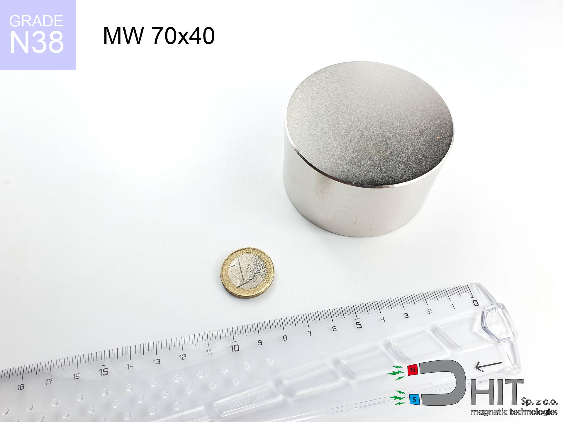
MW 70x40 / N38 - cylindrical magnet
cylindrical magnet
Catalog no 010097
GTIN/EAN: 5906301810964
Diameter Ø
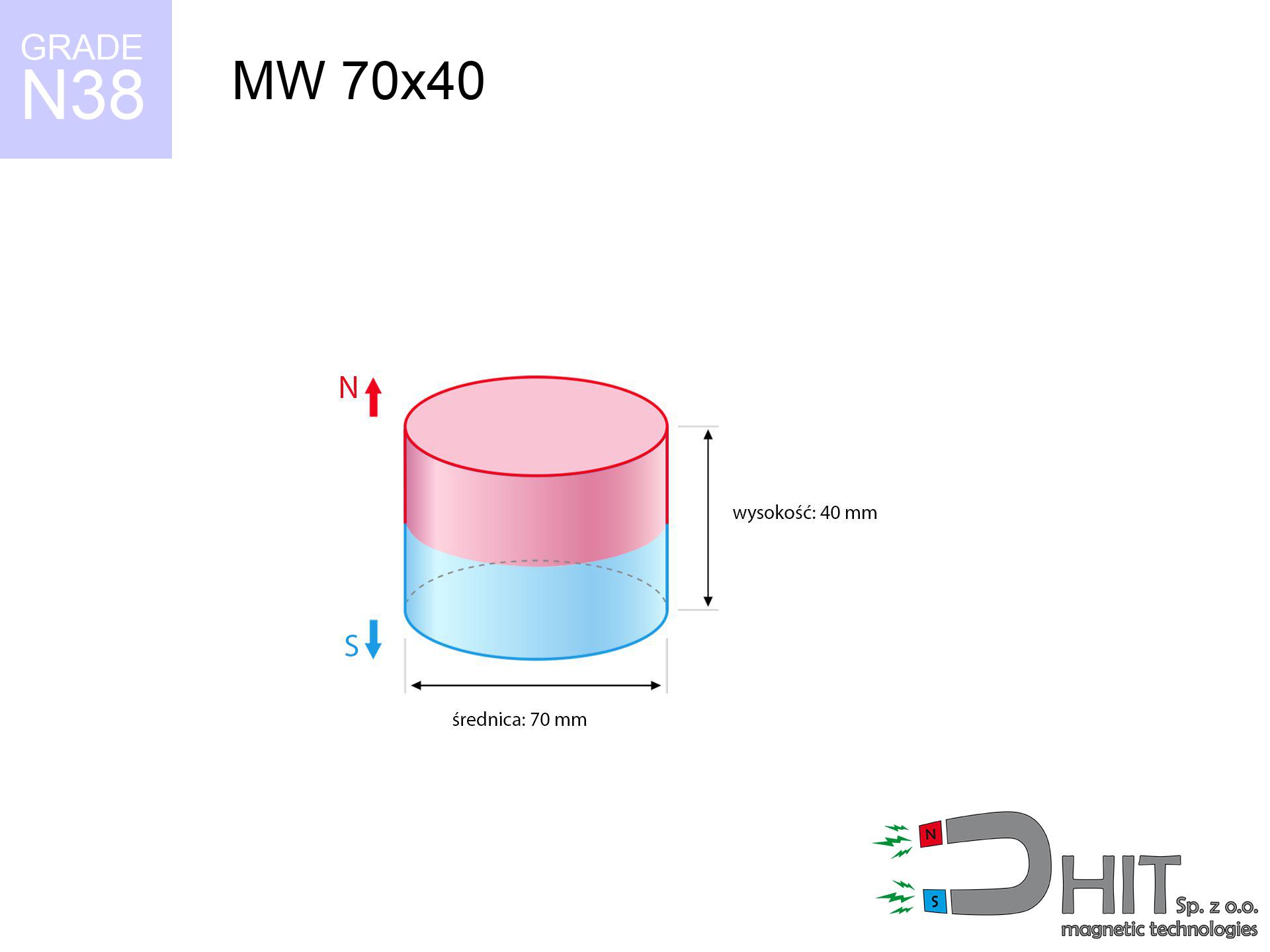
70 mm [±0,1 mm]
Height
40 mm [±0,1 mm]
Weight
1154.54 g
Magnetization Direction
↑ axial
Load capacity
164.24 kg / 1611.16 N
Magnetic Induction
466.52 mT / 4665 Gs
Coating
[NiCuNi] Nickel
395.40 ZŁ with VAT / pcs + price for transport
321.46 ZŁ net + 23% VAT / pcs
bulk discounts:
Need more?Engineering report for this magnet
Full PDF analysis: pull and shear force, effect of distance, temperature and plate thickness, safety distances and the demagnetization curve.
Give us a call
+48 22 499 98 98
or drop us a message via
request form
the contact page.
Specifications as well as form of magnets can be tested using our
online calculation tool.
Same-day shipping for orders placed before 14:00.
Technical specification of the product - MW 70x40 / N38 - cylindrical magnet
Specification / characteristics - MW 70x40 / N38 - cylindrical magnet
| properties | values |
|---|---|
| Cat. no. | 010097 |
| GTIN/EAN | 5906301810964 |
| Production/Distribution | Dhit sp. z o.o. |
| Country of origin | Poland / China / Germany |
| Customs code | 85059029 |
| Diameter Ø | 70 mm [±0,1 mm] |
| Height | 40 mm [±0,1 mm] |
| Weight | 1154.54 g |
| Magnetization Direction | ↑ axial |
| Load capacity ~ ? | 164.24 kg / 1611.16 N |
| Magnetic Induction ~ ? | 466.52 mT / 4665 Gs |
| Coating | [NiCuNi] Nickel |
| Manufacturing Tolerance | ±0.1 mm |
Magnetic properties of material N38
| properties | values | units |
|---|---|---|
| remenance Br [min. - max.] ? | 12.2-12.6 | kGs |
| remenance Br [min. - max.] ? | 1220-1260 | mT |
| coercivity bHc ? | 10.8-11.5 | kOe |
| coercivity bHc ? | 860-915 | kA/m |
| actual internal force iHc | ≥ 12 | kOe |
| actual internal force iHc | ≥ 955 | kA/m |
| energy density [min. - max.] ? | 36-38 | BH max MGOe |
| energy density [min. - max.] ? | 287-303 | BH max KJ/m |
| max. temperature ? | ≤ 80 | °C |
Physical properties of sintered neodymium magnets Nd2Fe14B at 20°C
| properties | values | units |
|---|---|---|
| Vickers hardness | ≥550 | Hv |
| Density | ≥7.4 | g/cm3 |
| Curie Temperature TC | 312 - 380 | °C |
| Curie Temperature TF | 593 - 716 | °F |
| Specific resistance | 150 | μΩ⋅cm |
| Bending strength | 250 | MPa |
| Compressive strength | 1000~1100 | MPa |
| Thermal expansion parallel (∥) to orientation (M) | (3-4) x 10-6 | °C-1 |
| Thermal expansion perpendicular (⊥) to orientation (M) | -(1-3) x 10-6 | °C-1 |
| Young's modulus | 1.7 x 10⁴ | kg/mm² |
Physical modeling of the product - technical parameters
The following values are the result of a physical simulation. Values were calculated on models for the class Nd2Fe14B. Actual conditions may deviate from the simulation results. Use these calculations as a preliminary roadmap when designing systems.
Table 1: Static force (force vs gap) - interaction chart
MW 70x40 / N38
| Distance (mm) | Induction (Gauss) / mT | Pull Force (kg/lbs/g/N) | Risk Status |
|---|---|---|---|
| 0 mm |
4665 Gs
466.5 mT
|
164.24 kg / 362.09 lbs
164240.0 g / 1611.2 N
|
crushing |
| 1 mm |
4538 Gs
453.8 mT
|
155.47 kg / 342.75 lbs
155467.9 g / 1525.1 N
|
crushing |
| 2 mm |
4409 Gs
440.9 mT
|
146.74 kg / 323.52 lbs
146744.5 g / 1439.6 N
|
crushing |
| 3 mm |
4279 Gs
427.9 mT
|
138.20 kg / 304.68 lbs
138201.8 g / 1355.8 N
|
crushing |
| 5 mm |
4017 Gs
401.7 mT
|
121.81 kg / 268.54 lbs
121806.5 g / 1194.9 N
|
crushing |
| 10 mm |
3376 Gs
337.6 mT
|
86.03 kg / 189.65 lbs
86025.3 g / 843.9 N
|
crushing |
| 15 mm |
2788 Gs
278.8 mT
|
58.69 kg / 129.38 lbs
58686.8 g / 575.7 N
|
crushing |
| 20 mm |
2279 Gs
227.9 mT
|
39.22 kg / 86.46 lbs
39215.6 g / 384.7 N
|
crushing |
| 30 mm |
1511 Gs
151.1 mT
|
17.22 kg / 37.97 lbs
17222.5 g / 169.0 N
|
crushing |
| 50 mm |
699 Gs
69.9 mT
|
3.69 kg / 8.13 lbs
3690.0 g / 36.2 N
|
medium risk |
Table 2: Slippage force (vertical surface)
MW 70x40 / N38
| Distance (mm) | Friction coefficient | Pull Force (kg/lbs/g/N) |
|---|---|---|
| 0 mm | Stal (~0.2) |
32.85 kg / 72.42 lbs
32848.0 g / 322.2 N
|
| 1 mm | Stal (~0.2) |
31.09 kg / 68.55 lbs
31094.0 g / 305.0 N
|
| 2 mm | Stal (~0.2) |
29.35 kg / 64.70 lbs
29348.0 g / 287.9 N
|
| 3 mm | Stal (~0.2) |
27.64 kg / 60.94 lbs
27640.0 g / 271.1 N
|
| 5 mm | Stal (~0.2) |
24.36 kg / 53.71 lbs
24362.0 g / 239.0 N
|
| 10 mm | Stal (~0.2) |
17.21 kg / 37.93 lbs
17206.0 g / 168.8 N
|
| 15 mm | Stal (~0.2) |
11.74 kg / 25.88 lbs
11738.0 g / 115.1 N
|
| 20 mm | Stal (~0.2) |
7.84 kg / 17.29 lbs
7844.0 g / 76.9 N
|
| 30 mm | Stal (~0.2) |
3.44 kg / 7.59 lbs
3444.0 g / 33.8 N
|
| 50 mm | Stal (~0.2) |
0.74 kg / 1.63 lbs
738.0 g / 7.2 N
|
Table 3: Wall mounting (shearing) - behavior on slippery surfaces
MW 70x40 / N38
| Surface type | Friction coefficient / % Mocy | Max load (kg/lbs/g/N) |
|---|---|---|
| Raw steel |
µ = 0.3
30% Nominalnej Siły
|
49.27 kg / 108.63 lbs
49272.0 g / 483.4 N
|
| Painted steel (standard) |
µ = 0.2
20% Nominalnej Siły
|
32.85 kg / 72.42 lbs
32848.0 g / 322.2 N
|
| Oily/slippery steel |
µ = 0.1
10% Nominalnej Siły
|
16.42 kg / 36.21 lbs
16424.0 g / 161.1 N
|
| Magnet with anti-slip rubber |
µ = 0.5
50% Nominalnej Siły
|
82.12 kg / 181.04 lbs
82120.0 g / 805.6 N
|
Table 4: Material efficiency (substrate influence) - power losses
MW 70x40 / N38
| Steel thickness (mm) | % power | Real pull force (kg/lbs/g/N) |
|---|---|---|
| 0.5 mm |
|
5.47 kg / 12.07 lbs
5474.7 g / 53.7 N
|
| 1 mm |
|
13.69 kg / 30.17 lbs
13686.7 g / 134.3 N
|
| 2 mm |
|
27.37 kg / 60.35 lbs
27373.3 g / 268.5 N
|
| 3 mm |
|
41.06 kg / 90.52 lbs
41060.0 g / 402.8 N
|
| 5 mm |
|
68.43 kg / 150.87 lbs
68433.3 g / 671.3 N
|
| 10 mm |
|
136.87 kg / 301.74 lbs
136866.7 g / 1342.7 N
|
| 11 mm |
|
150.55 kg / 331.91 lbs
150553.3 g / 1476.9 N
|
| 12 mm |
|
164.24 kg / 362.09 lbs
164240.0 g / 1611.2 N
|
Table 5: Thermal resistance (stability) - resistance threshold
MW 70x40 / N38
| Ambient temp. (°C) | Power loss | Remaining pull (kg/lbs/g/N) | Status |
|---|---|---|---|
| 20 °C | 0.0% |
164.24 kg / 362.09 lbs
164240.0 g / 1611.2 N
|
OK |
| 40 °C | -2.2% |
160.63 kg / 354.12 lbs
160626.7 g / 1575.7 N
|
OK |
| 60 °C | -4.4% |
157.01 kg / 346.15 lbs
157013.4 g / 1540.3 N
|
OK |
| 80 °C | -6.6% |
153.40 kg / 338.19 lbs
153400.2 g / 1504.9 N
|
|
| 100 °C | -28.8% |
116.94 kg / 257.81 lbs
116938.9 g / 1147.2 N
|
Table 6: Two magnets (repulsion) - field range
MW 70x40 / N38
| Gap (mm) | Attraction (kg/lbs) (N-S) | Lateral Force (kg/lbs/g/N) | Repulsion (kg/lbs) (N-N) |
|---|---|---|---|
| 0 mm |
516.26 kg / 1138.16 lbs
5 679 Gs
|
77.44 kg / 170.72 lbs
77439 g / 759.7 N
|
N/A |
| 1 mm |
502.57 kg / 1107.98 lbs
9 205 Gs
|
75.39 kg / 166.20 lbs
75385 g / 739.5 N
|
452.31 kg / 997.18 lbs
~0 Gs
|
| 2 mm |
488.69 kg / 1077.37 lbs
9 077 Gs
|
73.30 kg / 161.61 lbs
73303 g / 719.1 N
|
439.82 kg / 969.63 lbs
~0 Gs
|
| 3 mm |
474.91 kg / 1047.01 lbs
8 948 Gs
|
71.24 kg / 157.05 lbs
71237 g / 698.8 N
|
427.42 kg / 942.31 lbs
~0 Gs
|
| 5 mm |
447.76 kg / 987.15 lbs
8 688 Gs
|
67.16 kg / 148.07 lbs
67164 g / 658.9 N
|
402.99 kg / 888.43 lbs
~0 Gs
|
| 10 mm |
382.88 kg / 844.10 lbs
8 034 Gs
|
57.43 kg / 126.62 lbs
57432 g / 563.4 N
|
344.59 kg / 759.69 lbs
~0 Gs
|
| 20 mm |
270.41 kg / 596.14 lbs
6 752 Gs
|
40.56 kg / 89.42 lbs
40561 g / 397.9 N
|
243.37 kg / 536.53 lbs
~0 Gs
|
| 50 mm |
81.66 kg / 180.03 lbs
3 710 Gs
|
12.25 kg / 27.01 lbs
12249 g / 120.2 N
|
73.50 kg / 162.03 lbs
~0 Gs
|
| 60 mm |
54.14 kg / 119.35 lbs
3 021 Gs
|
8.12 kg / 17.90 lbs
8120 g / 79.7 N
|
48.72 kg / 107.41 lbs
~0 Gs
|
| 70 mm |
36.14 kg / 79.69 lbs
2 469 Gs
|
5.42 kg / 11.95 lbs
5422 g / 53.2 N
|
32.53 kg / 71.72 lbs
~0 Gs
|
| 80 mm |
24.40 kg / 53.80 lbs
2 028 Gs
|
3.66 kg / 8.07 lbs
3661 g / 35.9 N
|
21.96 kg / 48.42 lbs
~0 Gs
|
| 90 mm |
16.70 kg / 36.82 lbs
1 678 Gs
|
2.51 kg / 5.52 lbs
2505 g / 24.6 N
|
15.03 kg / 33.14 lbs
~0 Gs
|
| 100 mm |
11.60 kg / 25.57 lbs
1 398 Gs
|
1.74 kg / 3.84 lbs
1740 g / 17.1 N
|
10.44 kg / 23.01 lbs
~0 Gs
|
Table 7: Safety (HSE) (implants) - warnings
MW 70x40 / N38
| Object / Device | Limit (Gauss) / mT | Safe distance |
|---|---|---|
| Pacemaker | 5 Gs (0.5 mT) | 37.5 cm |
| Hearing aid | 10 Gs (1.0 mT) | 29.5 cm |
| Timepiece | 20 Gs (2.0 mT) | 23.0 cm |
| Mobile device | 40 Gs (4.0 mT) | 17.5 cm |
| Car key | 50 Gs (5.0 mT) | 16.5 cm |
| Payment card | 400 Gs (40.0 mT) | 7.0 cm |
| HDD hard drive | 600 Gs (60.0 mT) | 5.5 cm |
Table 8: Collisions (cracking risk) - collision effects
MW 70x40 / N38
| Start from (mm) | Speed (km/h) | Energy (J) | Predicted outcome |
|---|---|---|---|
| 10 mm |
15.47 km/h
(4.30 m/s)
|
10.66 J | |
| 30 mm |
22.16 km/h
(6.15 m/s)
|
21.87 J | |
| 50 mm |
27.27 km/h
(7.58 m/s)
|
33.13 J | |
| 100 mm |
38.07 km/h
(10.57 m/s)
|
64.55 J |
Table 9: Corrosion resistance
MW 70x40 / N38
| Technical parameter | Value / Description |
|---|---|
| Coating type | [NiCuNi] Nickel |
| Layer structure | Nickel - Copper - Nickel |
| Layer thickness | 10-20 µm |
| Salt spray test (SST) ? | 24 h |
| Recommended environment | Indoors only (dry) |
Table 10: Construction data (Flux)
MW 70x40 / N38
| Parameter | Value | SI Unit / Description |
|---|---|---|
| Magnetic Flux | 180 982 Mx | 1809.8 µWb |
| Pc Coefficient | 0.64 | High (Stable) |
Table 11: Physics of underwater searching
MW 70x40 / N38
| Environment | Effective steel pull | Effect |
|---|---|---|
| Air (land) | 164.24 kg | Standard |
| Water (riverbed) |
188.05 kg
(+23.81 kg buoyancy gain)
|
+14.5% |
1. Wall mount (shear)
*Note: On a vertical surface, the magnet holds only a fraction of its perpendicular strength.
2. Steel saturation
*Thin steel (e.g. 0.5mm PC case) significantly limits the holding force.
3. Temperature resistance
*For N38 material, the safety limit is 80°C.
4. Demagnetization curve and operating point (B-H)
chart generated for the permeance coefficient Pc (Permeance Coefficient) = 0.64
The chart above illustrates the magnetic characteristics of the material within the second quadrant of the hysteresis loop. The solid red line represents the demagnetization curve (material potential), while the dashed blue line is the load line based on the magnet's geometry. The Pc (Permeance Coefficient), also known as the load line slope, is a dimensionless value that describes the relationship between the magnet's shape and its magnetic stability. The intersection of these two lines (the black dot) is the operating point — it determines the actual magnetic flux density generated by the magnet in this specific configuration. A higher Pc value means the magnet is more 'slender' (tall relative to its area), resulting in a higher operating point and better resistance to irreversible demagnetization caused by external fields or temperature. A value of 0.42 is relatively low (typical for flat magnets), meaning the operating point is closer to the 'knee' of the curve — caution is advised when operating at temperatures near the maximum limit to avoid strength loss.
Elemental analysis
| iron (Fe) | 64% – 68% |
| neodymium (Nd) | 29% – 32% |
| boron (B) | 1.1% – 1.2% |
| dysprosium (Dy) | 0.5% – 2.0% |
| coating (Ni-Cu-Ni) | < 0.05% |
Ecology and recycling (GPSR)
| recyclability (EoL) | 100% |
| recycled raw materials | ~10% (pre-cons) |
| carbon footprint | low / zredukowany |
| waste code (EWC) | 16 02 16 |
Other offers
![SM 32x300 [2xM8] / N42 - magnetic separator](https://cdn3.dhit.pl/graphics/products/sm-32x300-2xm8-pel.jpg "SM 32x300 [2xM8] / N42 - magnetic separator")

![SM 32x475 [2xM8] / N52 - magnetic separator](https://cdn3.dhit.pl/graphics/products/sm-32x475-2xm8-wef.jpg "SM 32x475 [2xM8] / N52 - magnetic separator")

Strengths as well as weaknesses of rare earth magnets.
Pros
- They have constant strength, and over nearly 10 years their attraction force decreases symbolically – ~1% (according to theory),
- They maintain their magnetic properties even under external field action,
- In other words, due to the metallic finish of silver, the element gains visual value,
- Neodymium magnets create maximum magnetic induction on a contact point, which allows for strong attraction,
- Thanks to resistance to high temperature, they are capable of working (depending on the shape) even at temperatures up to 230°C and higher...
- Considering the potential of accurate forming and customization to individualized requirements, neodymium magnets can be produced in a wide range of shapes and sizes, which expands the range of possible applications,
- Universal use in modern industrial fields – they find application in HDD drives, brushless drives, medical equipment, also complex engineering applications.
- Relatively small size with high pulling force – neodymium magnets offer high power in compact dimensions, which enables their usage in small systems
Weaknesses
- They are fragile upon too strong impacts. To avoid cracks, it is worth protecting magnets using a steel holder. Such protection not only protects the magnet but also increases its resistance to damage
- We warn that neodymium magnets can lose their power at high temperatures. To prevent this, we advise our specialized [AH] magnets, which work effectively even at 230°C.
- Magnets exposed to a humid environment can corrode. Therefore while using outdoors, we advise using water-impermeable magnets made of rubber, plastic or other material resistant to moisture
- Limited ability of creating nuts in the magnet and complicated forms - recommended is cover - magnet mounting.
- Potential hazard related to microscopic parts of magnets are risky, when accidentally swallowed, which gains importance in the aspect of protecting the youngest. Furthermore, tiny parts of these magnets are able to complicate diagnosis medical when they are in the body.
- With large orders the cost of neodymium magnets is economically unviable,
Lifting parameters
Magnetic strength at its maximum – what contributes to it?
- on a base made of structural steel, perfectly concentrating the magnetic flux
- possessing a thickness of minimum 10 mm to ensure full flux closure
- with a surface free of scratches
- without any insulating layer between the magnet and steel
- under vertical force direction (90-degree angle)
- in neutral thermal conditions
Practical aspects of lifting capacity – factors
- Gap (betwixt the magnet and the metal), because even a very small clearance (e.g. 0.5 mm) can cause a decrease in force by up to 50% (this also applies to paint, corrosion or debris).
- Load vector – maximum parameter is reached only during perpendicular pulling. The force required to slide of the magnet along the surface is standardly many times lower (approx. 1/5 of the lifting capacity).
- Substrate thickness – for full efficiency, the steel must be sufficiently thick. Thin sheet restricts the attraction force (the magnet "punches through" it).
- Material type – ideal substrate is high-permeability steel. Stainless steels may attract less.
- Surface quality – the more even the surface, the larger the contact zone and stronger the hold. Unevenness acts like micro-gaps.
- Thermal environment – heating the magnet results in weakening of force. It is worth remembering the thermal limit for a given model.
Holding force was checked on the plate surface of 20 mm thickness, when the force acted perpendicularly, however under parallel forces the lifting capacity is smaller. Moreover, even a small distance between the magnet’s surface and the plate reduces the lifting capacity.
H&S for magnets
Swallowing risk
Only for adults. Tiny parts pose a choking risk, causing serious injuries. Keep out of reach of kids and pets.
Electronic devices
Data protection: Neodymium magnets can damage data carriers and sensitive devices (heart implants, hearing aids, mechanical watches).
ICD Warning
People with a pacemaker must maintain an absolute distance from magnets. The magnetism can disrupt the operation of the implant.
Avoid contact if allergic
It is widely known that the nickel plating (the usual finish) is a strong allergen. If your skin reacts to metals, avoid direct skin contact or opt for encased magnets.
Finger safety
Protect your hands. Two large magnets will snap together immediately with a force of several hundred kilograms, crushing everything in their path. Exercise extreme caution!
GPS and phone interference
Note: rare earth magnets produce a field that confuses sensitive sensors. Keep a safe distance from your phone, device, and GPS.
Mechanical processing
Machining of neodymium magnets carries a risk of fire hazard. Neodymium dust oxidizes rapidly with oxygen and is difficult to extinguish.
Eye protection
Despite metallic appearance, the material is brittle and not impact-resistant. Do not hit, as the magnet may shatter into sharp, dangerous pieces.
Demagnetization risk
Regular neodymium magnets (grade N) lose power when the temperature exceeds 80°C. This process is irreversible.
Safe operation
Before starting, read the rules. Sudden snapping can break the magnet or injure your hand. Think ahead.
Tabela kosztu i czasu dostawy
Płatność przed wysyłką:

GLS kurier
Przesyłka będzie u Ciebie za 2-3 dni
14.99 ZŁ

InPost Paczkomaty 24/7
Przesyłka będzie u Ciebie za 1-2 dni
12.30 ZŁ
Płatność przy odbiorze (pobranie):
GLS kurier
Przesyłka będzie u Ciebie za 1-2 dni
23.00 ZŁ
Rate the product
Your rating