
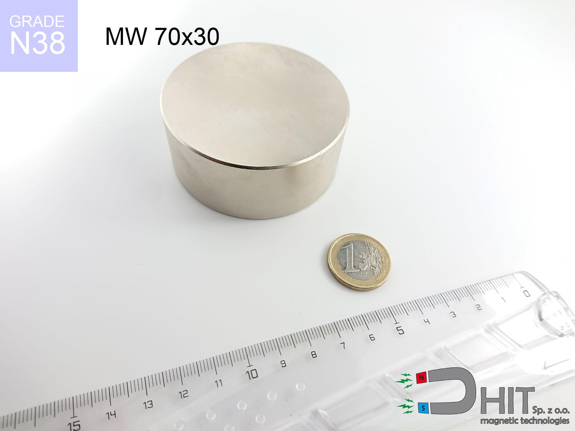
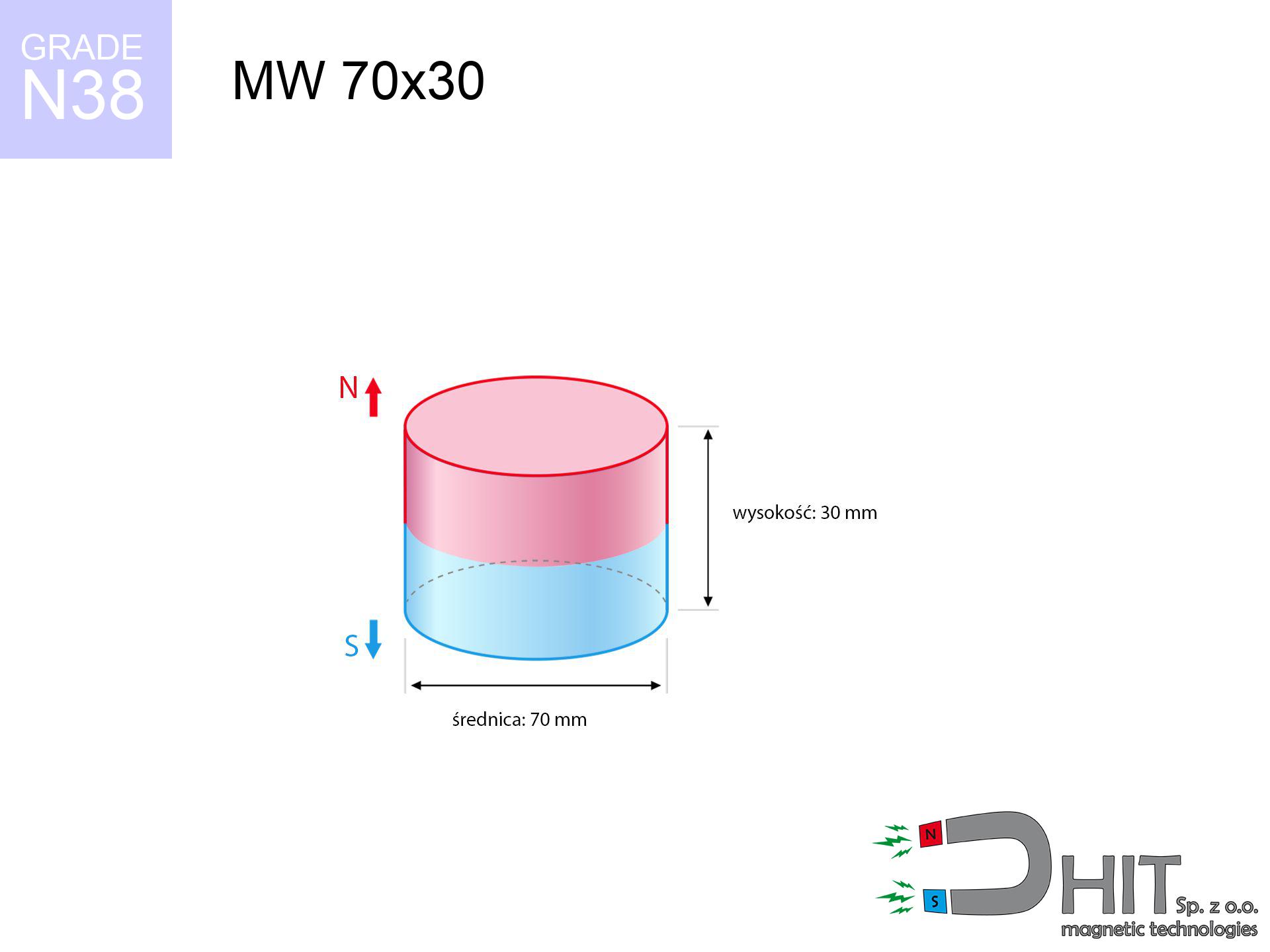
MW 70x30 / N38 - cylindrical magnet
cylindrical magnet
Catalog no 010096
GTIN/EAN: 5906301810957
Diameter Ø
70 mm [±0,1 mm]
Height
30 mm [±0,1 mm]
Weight
865.9 g
Magnetization Direction
↑ axial
Load capacity
144.18 kg / 1414.37 N
Magnetic Induction
403.43 mT / 4034 Gs
Coating
[NiCuNi] Nickel
317.17 ZŁ with VAT / pcs + price for transport
257.86 ZŁ net + 23% VAT / pcs
bulk discounts:
Need more?Engineering report for this magnet
Full PDF analysis: pull and shear force, effect of distance, temperature and plate thickness, safety distances and the demagnetization curve.
Contact us by phone
+48 888 99 98 98
otherwise send us a note through
form
the contact section.
Specifications as well as form of a neodymium magnet can be tested on our
modular calculator.
Same-day processing for orders placed before 14:00.
Technical - MW 70x30 / N38 - cylindrical magnet
Specification / characteristics - MW 70x30 / N38 - cylindrical magnet
| properties | values |
|---|---|
| Cat. no. | 010096 |
| GTIN/EAN | 5906301810957 |
| Production/Distribution | Dhit sp. z o.o. |
| Country of origin | Poland / China / Germany |
| Customs code | 85059029 |
| Diameter Ø | 70 mm [±0,1 mm] |
| Height | 30 mm [±0,1 mm] |
| Weight | 865.9 g |
| Magnetization Direction | ↑ axial |
| Load capacity ~ ? | 144.18 kg / 1414.37 N |
| Magnetic Induction ~ ? | 403.43 mT / 4034 Gs |
| Coating | [NiCuNi] Nickel |
| Manufacturing Tolerance | ±0.1 mm |
Magnetic properties of material N38
| properties | values | units |
|---|---|---|
| remenance Br [min. - max.] ? | 12.2-12.6 | kGs |
| remenance Br [min. - max.] ? | 1220-1260 | mT |
| coercivity bHc ? | 10.8-11.5 | kOe |
| coercivity bHc ? | 860-915 | kA/m |
| actual internal force iHc | ≥ 12 | kOe |
| actual internal force iHc | ≥ 955 | kA/m |
| energy density [min. - max.] ? | 36-38 | BH max MGOe |
| energy density [min. - max.] ? | 287-303 | BH max KJ/m |
| max. temperature ? | ≤ 80 | °C |
Physical properties of sintered neodymium magnets Nd2Fe14B at 20°C
| properties | values | units |
|---|---|---|
| Vickers hardness | ≥550 | Hv |
| Density | ≥7.4 | g/cm3 |
| Curie Temperature TC | 312 - 380 | °C |
| Curie Temperature TF | 593 - 716 | °F |
| Specific resistance | 150 | μΩ⋅cm |
| Bending strength | 250 | MPa |
| Compressive strength | 1000~1100 | MPa |
| Thermal expansion parallel (∥) to orientation (M) | (3-4) x 10-6 | °C-1 |
| Thermal expansion perpendicular (⊥) to orientation (M) | -(1-3) x 10-6 | °C-1 |
| Young's modulus | 1.7 x 10⁴ | kg/mm² |
Engineering analysis of the product - technical parameters
Presented data are the result of a mathematical calculation. Values rely on models for the material Nd2Fe14B. Operational conditions may deviate from the simulation results. Use these data as a supplementary guide for designers.
Table 1: Static pull force (pull vs gap) - interaction chart
MW 70x30 / N38
| Distance (mm) | Induction (Gauss) / mT | Pull Force (kg/lbs/g/N) | Risk Status |
|---|---|---|---|
| 0 mm |
4034 Gs
403.4 mT
|
144.18 kg / 317.86 LBS
144180.0 g / 1414.4 N
|
critical level |
| 1 mm |
3934 Gs
393.4 mT
|
137.11 kg / 302.27 LBS
137108.9 g / 1345.0 N
|
critical level |
| 2 mm |
3830 Gs
383.0 mT
|
129.96 kg / 286.52 LBS
129962.6 g / 1274.9 N
|
critical level |
| 3 mm |
3724 Gs
372.4 mT
|
122.86 kg / 270.87 LBS
122863.7 g / 1205.3 N
|
critical level |
| 5 mm |
3507 Gs
350.7 mT
|
108.99 kg / 240.28 LBS
108989.8 g / 1069.2 N
|
critical level |
| 10 mm |
2963 Gs
296.3 mT
|
77.77 kg / 171.46 LBS
77773.1 g / 763.0 N
|
critical level |
| 15 mm |
2452 Gs
245.2 mT
|
53.26 kg / 117.41 LBS
53257.6 g / 522.5 N
|
critical level |
| 20 mm |
2003 Gs
200.3 mT
|
35.55 kg / 78.38 LBS
35554.2 g / 348.8 N
|
critical level |
| 30 mm |
1321 Gs
132.1 mT
|
15.45 kg / 34.06 LBS
15450.6 g / 151.6 N
|
critical level |
| 50 mm |
601 Gs
60.1 mT
|
3.20 kg / 7.05 LBS
3199.7 g / 31.4 N
|
medium risk |
Table 2: Slippage load (wall)
MW 70x30 / N38
| Distance (mm) | Friction coefficient | Pull Force (kg/lbs/g/N) |
|---|---|---|
| 0 mm | Stal (~0.2) |
28.84 kg / 63.57 LBS
28836.0 g / 282.9 N
|
| 1 mm | Stal (~0.2) |
27.42 kg / 60.46 LBS
27422.0 g / 269.0 N
|
| 2 mm | Stal (~0.2) |
25.99 kg / 57.30 LBS
25992.0 g / 255.0 N
|
| 3 mm | Stal (~0.2) |
24.57 kg / 54.17 LBS
24572.0 g / 241.1 N
|
| 5 mm | Stal (~0.2) |
21.80 kg / 48.06 LBS
21798.0 g / 213.8 N
|
| 10 mm | Stal (~0.2) |
15.55 kg / 34.29 LBS
15554.0 g / 152.6 N
|
| 15 mm | Stal (~0.2) |
10.65 kg / 23.48 LBS
10652.0 g / 104.5 N
|
| 20 mm | Stal (~0.2) |
7.11 kg / 15.67 LBS
7110.0 g / 69.7 N
|
| 30 mm | Stal (~0.2) |
3.09 kg / 6.81 LBS
3090.0 g / 30.3 N
|
| 50 mm | Stal (~0.2) |
0.64 kg / 1.41 LBS
640.0 g / 6.3 N
|
Table 3: Vertical assembly (sliding) - behavior on slippery surfaces
MW 70x30 / N38
| Surface type | Friction coefficient / % Mocy | Max load (kg/lbs/g/N) |
|---|---|---|
| Raw steel |
µ = 0.3
30% Nominalnej Siły
|
43.25 kg / 95.36 LBS
43254.0 g / 424.3 N
|
| Painted steel (standard) |
µ = 0.2
20% Nominalnej Siły
|
28.84 kg / 63.57 LBS
28836.0 g / 282.9 N
|
| Oily/slippery steel |
µ = 0.1
10% Nominalnej Siły
|
14.42 kg / 31.79 LBS
14418.0 g / 141.4 N
|
| Magnet with anti-slip rubber |
µ = 0.5
50% Nominalnej Siły
|
72.09 kg / 158.93 LBS
72090.0 g / 707.2 N
|
Table 4: Steel thickness (saturation) - power losses
MW 70x30 / N38
| Steel thickness (mm) | % power | Real pull force (kg/lbs/g/N) |
|---|---|---|
| 0.5 mm |
|
4.81 kg / 10.60 LBS
4806.0 g / 47.1 N
|
| 1 mm |
|
12.01 kg / 26.49 LBS
12015.0 g / 117.9 N
|
| 2 mm |
|
24.03 kg / 52.98 LBS
24030.0 g / 235.7 N
|
| 3 mm |
|
36.05 kg / 79.47 LBS
36045.0 g / 353.6 N
|
| 5 mm |
|
60.08 kg / 132.44 LBS
60075.0 g / 589.3 N
|
| 10 mm |
|
120.15 kg / 264.89 LBS
120150.0 g / 1178.7 N
|
| 11 mm |
|
132.17 kg / 291.37 LBS
132165.0 g / 1296.5 N
|
| 12 mm |
|
144.18 kg / 317.86 LBS
144180.0 g / 1414.4 N
|
Table 5: Thermal resistance (material behavior) - power drop
MW 70x30 / N38
| Ambient temp. (°C) | Power loss | Remaining pull (kg/lbs/g/N) | Status |
|---|---|---|---|
| 20 °C | 0.0% |
144.18 kg / 317.86 LBS
144180.0 g / 1414.4 N
|
OK |
| 40 °C | -2.2% |
141.01 kg / 310.87 LBS
141008.0 g / 1383.3 N
|
OK |
| 60 °C | -4.4% |
137.84 kg / 303.88 LBS
137836.1 g / 1352.2 N
|
|
| 80 °C | -6.6% |
134.66 kg / 296.88 LBS
134664.1 g / 1321.1 N
|
|
| 100 °C | -28.8% |
102.66 kg / 226.32 LBS
102656.2 g / 1007.1 N
|
Table 6: Magnet-Magnet interaction (repulsion) - field range
MW 70x30 / N38
| Gap (mm) | Attraction (kg/lbs) (N-S) | Lateral Force (kg/lbs/g/N) | Repulsion (kg/lbs) (N-N) |
|---|---|---|---|
| 0 mm |
386.08 kg / 851.15 LBS
5 354 Gs
|
57.91 kg / 127.67 LBS
57911 g / 568.1 N
|
N/A |
| 1 mm |
376.71 kg / 830.51 LBS
7 969 Gs
|
56.51 kg / 124.58 LBS
56507 g / 554.3 N
|
339.04 kg / 747.46 LBS
~0 Gs
|
| 2 mm |
367.14 kg / 809.41 LBS
7 867 Gs
|
55.07 kg / 121.41 LBS
55071 g / 540.2 N
|
330.43 kg / 728.47 LBS
~0 Gs
|
| 3 mm |
357.57 kg / 788.30 LBS
7 764 Gs
|
53.63 kg / 118.24 LBS
53635 g / 526.2 N
|
321.81 kg / 709.47 LBS
~0 Gs
|
| 5 mm |
338.48 kg / 746.21 LBS
7 554 Gs
|
50.77 kg / 111.93 LBS
50772 g / 498.1 N
|
304.63 kg / 671.59 LBS
~0 Gs
|
| 10 mm |
291.85 kg / 643.41 LBS
7 014 Gs
|
43.78 kg / 96.51 LBS
43777 g / 429.5 N
|
262.66 kg / 579.07 LBS
~0 Gs
|
| 20 mm |
208.26 kg / 459.13 LBS
5 925 Gs
|
31.24 kg / 68.87 LBS
31238 g / 306.4 N
|
187.43 kg / 413.21 LBS
~0 Gs
|
| 50 mm |
62.81 kg / 138.47 LBS
3 254 Gs
|
9.42 kg / 20.77 LBS
9421 g / 92.4 N
|
56.53 kg / 124.62 LBS
~0 Gs
|
| 60 mm |
41.37 kg / 91.21 LBS
2 641 Gs
|
6.21 kg / 13.68 LBS
6206 g / 60.9 N
|
37.24 kg / 82.09 LBS
~0 Gs
|
| 70 mm |
27.41 kg / 60.43 LBS
2 150 Gs
|
4.11 kg / 9.06 LBS
4112 g / 40.3 N
|
24.67 kg / 54.39 LBS
~0 Gs
|
| 80 mm |
18.35 kg / 40.46 LBS
1 759 Gs
|
2.75 kg / 6.07 LBS
2753 g / 27.0 N
|
16.52 kg / 36.41 LBS
~0 Gs
|
| 90 mm |
12.45 kg / 27.44 LBS
1 449 Gs
|
1.87 kg / 4.12 LBS
1867 g / 18.3 N
|
11.20 kg / 24.70 LBS
~0 Gs
|
| 100 mm |
8.57 kg / 18.89 LBS
1 202 Gs
|
1.29 kg / 2.83 LBS
1285 g / 12.6 N
|
7.71 kg / 17.00 LBS
~0 Gs
|
Table 7: Protective zones (electronics) - warnings
MW 70x30 / N38
| Object / Device | Limit (Gauss) / mT | Safe distance |
|---|---|---|
| Pacemaker | 5 Gs (0.5 mT) | 34.5 cm |
| Hearing aid | 10 Gs (1.0 mT) | 27.0 cm |
| Timepiece | 20 Gs (2.0 mT) | 21.0 cm |
| Phone / Smartphone | 40 Gs (4.0 mT) | 16.5 cm |
| Car key | 50 Gs (5.0 mT) | 15.0 cm |
| Payment card | 400 Gs (40.0 mT) | 6.5 cm |
| HDD hard drive | 600 Gs (60.0 mT) | 5.5 cm |
Table 8: Collisions (kinetic energy) - warning
MW 70x30 / N38
| Start from (mm) | Speed (km/h) | Energy (J) | Predicted outcome |
|---|---|---|---|
| 10 mm |
16.84 km/h
(4.68 m/s)
|
9.47 J | |
| 30 mm |
24.00 km/h
(6.67 m/s)
|
19.25 J | |
| 50 mm |
29.50 km/h
(8.19 m/s)
|
29.07 J | |
| 100 mm |
41.18 km/h
(11.44 m/s)
|
56.66 J |
Table 9: Anti-corrosion coating durability
MW 70x30 / N38
| Technical parameter | Value / Description |
|---|---|
| Coating type | [NiCuNi] Nickel |
| Layer structure | Nickel - Copper - Nickel |
| Layer thickness | 10-20 µm |
| Salt spray test (SST) ? | 24 h |
| Recommended environment | Indoors only (dry) |
Table 10: Electrical data (Pc)
MW 70x30 / N38
| Parameter | Value | SI Unit / Description |
|---|---|---|
| Magnetic Flux | 159 225 Mx | 1592.3 µWb |
| Pc Coefficient | 0.53 | Low (Flat) |
Table 11: Submerged application
MW 70x30 / N38
| Environment | Effective steel pull | Effect |
|---|---|---|
| Air (land) | 144.18 kg | Standard |
| Water (riverbed) |
165.09 kg
(+20.91 kg buoyancy gain)
|
+14.5% |
1. Wall mount (shear)
*Note: On a vertical wall, the magnet holds just ~20% of its perpendicular strength.
2. Steel saturation
*Thin metal sheet (e.g. computer case) significantly reduces the holding force.
3. Thermal stability
*For N38 material, the critical limit is 80°C.
4. Demagnetization curve and operating point (B-H)
chart generated for the permeance coefficient Pc (Permeance Coefficient) = 0.53
This simulation demonstrates the magnetic stability of the selected magnet under specific geometric conditions. The solid red line represents the demagnetization curve (material potential), while the dashed blue line is the load line based on the magnet's geometry. The Pc (Permeance Coefficient), also known as the load line slope, is a dimensionless value that describes the relationship between the magnet's shape and its magnetic stability. The intersection of these two lines (the black dot) is the operating point — it determines the actual magnetic flux density generated by the magnet in this specific configuration. A higher Pc value means the magnet is more 'slender' (tall relative to its area), resulting in a higher operating point and better resistance to irreversible demagnetization caused by external fields or temperature. A value of 0.42 is relatively low (typical for flat magnets), meaning the operating point is closer to the 'knee' of the curve — caution is advised when operating at temperatures near the maximum limit to avoid strength loss.
Chemical composition
| iron (Fe) | 64% – 68% |
| neodymium (Nd) | 29% – 32% |
| boron (B) | 1.1% – 1.2% |
| dysprosium (Dy) | 0.5% – 2.0% |
| coating (Ni-Cu-Ni) | < 0.05% |
Ecology and recycling (GPSR)
| recyclability (EoL) | 100% |
| recycled raw materials | ~10% (pre-cons) |
| carbon footprint | low / zredukowany |
| waste code (EWC) | 16 02 16 |
Other deals

![HH 16x5.3 [M3] / N38 - through hole magnetic holder](https://cdn3.dhit.pl/graphics/products/hh-16x5.3-m3-sud.jpg "HH 16x5.3 [M3] / N38 - through hole magnetic holder")

Strengths as well as weaknesses of Nd2Fe14B magnets.
Advantages
- They do not lose magnetism, even after approximately ten years – the drop in lifting capacity is only ~1% (theoretically),
- They are noted for resistance to demagnetization induced by presence of other magnetic fields,
- A magnet with a smooth gold surface looks better,
- Neodymium magnets ensure maximum magnetic induction on a small area, which allows for strong attraction,
- Neodymium magnets are characterized by extremely high magnetic induction on the magnet surface and are able to act (depending on the shape) even at a temperature of 230°C or more...
- Thanks to versatility in designing and the ability to modify to specific needs,
- Wide application in future technologies – they are used in data components, brushless drives, advanced medical instruments, as well as other advanced devices.
- Compactness – despite small sizes they provide effective action, making them ideal for precision applications
Weaknesses
- At strong impacts they can break, therefore we recommend placing them in steel cases. A metal housing provides additional protection against damage, as well as increases the magnet's durability.
- Neodymium magnets decrease their power under the influence of heating. As soon as 80°C is exceeded, many of them start losing their power. Therefore, we recommend our special magnets marked [AH], which maintain stability even at temperatures up to 230°C
- Due to the susceptibility of magnets to corrosion in a humid environment, we advise using waterproof magnets made of rubber, plastic or other material immune to moisture, when using outdoors
- We suggest cover - magnetic holder, due to difficulties in realizing threads inside the magnet and complicated shapes.
- Health risk related to microscopic parts of magnets pose a threat, if swallowed, which becomes key in the context of child health protection. Furthermore, small components of these devices are able to complicate diagnosis medical after entering the body.
- Higher cost of purchase is a significant factor to consider compared to ceramic magnets, especially in budget applications
Holding force characteristics
Breakaway strength of the magnet in ideal conditions – what it depends on?
- on a plate made of mild steel, optimally conducting the magnetic field
- possessing a thickness of at least 10 mm to ensure full flux closure
- characterized by even structure
- under conditions of ideal adhesion (surface-to-surface)
- during detachment in a direction vertical to the mounting surface
- at ambient temperature room level
Impact of factors on magnetic holding capacity in practice
- Clearance – the presence of any layer (paint, tape, air) interrupts the magnetic circuit, which lowers capacity rapidly (even by 50% at 0.5 mm).
- Loading method – declared lifting capacity refers to pulling vertically. When slipping, the magnet holds much less (often approx. 20-30% of maximum force).
- Wall thickness – the thinner the sheet, the weaker the hold. Magnetic flux passes through the material instead of converting into lifting capacity.
- Steel type – mild steel attracts best. Alloy steels decrease magnetic permeability and holding force.
- Surface structure – the smoother and more polished the plate, the larger the contact zone and higher the lifting capacity. Unevenness acts like micro-gaps.
- Heat – neodymium magnets have a sensitivity to temperature. When it is hot they are weaker, and at low temperatures gain strength (up to a certain limit).
Lifting capacity was measured using a steel plate with a smooth surface of suitable thickness (min. 20 mm), under perpendicular detachment force, whereas under attempts to slide the magnet the lifting capacity is smaller. Additionally, even a minimal clearance between the magnet and the plate decreases the holding force.
Safety rules for work with neodymium magnets
Do not drill into magnets
Machining of NdFeB material carries a risk of fire risk. Magnetic powder reacts violently with oxygen and is difficult to extinguish.
Do not underestimate power
Before starting, check safety instructions. Sudden snapping can destroy the magnet or hurt your hand. Think ahead.
Nickel allergy
Nickel alert: The nickel-copper-nickel coating contains nickel. If redness appears, immediately stop handling magnets and use protective gear.
Eye protection
NdFeB magnets are ceramic materials, which means they are prone to chipping. Collision of two magnets will cause them breaking into shards.
GPS and phone interference
Note: neodymium magnets generate a field that confuses precision electronics. Maintain a safe distance from your mobile, tablet, and GPS.
Medical implants
Warning for patients: Strong magnetic fields affect medical devices. Keep minimum 30 cm distance or ask another person to handle the magnets.
Finger safety
Mind your fingers. Two powerful magnets will join instantly with a force of massive weight, crushing anything in their path. Be careful!
Magnetic media
Powerful magnetic fields can erase data on credit cards, HDDs, and other magnetic media. Maintain a gap of at least 10 cm.
Adults only
Strictly store magnets out of reach of children. Risk of swallowing is significant, and the effects of magnets connecting inside the body are life-threatening.
Heat warning
Keep cool. Neodymium magnets are sensitive to heat. If you need resistance above 80°C, look for HT versions (H, SH, UH).
Tabela kosztu i czasu dostawy
Płatność przed wysyłką:

GLS kurier
Przesyłka będzie u Ciebie za 2-3 dni
14.99 ZŁ

InPost Paczkomaty 24/7
Przesyłka będzie u Ciebie za 1-2 dni
12.30 ZŁ
Płatność przy odbiorze (pobranie):
GLS kurier
Przesyłka będzie u Ciebie za 1-2 dni
23.00 ZŁ
Rate the product
Your rating