
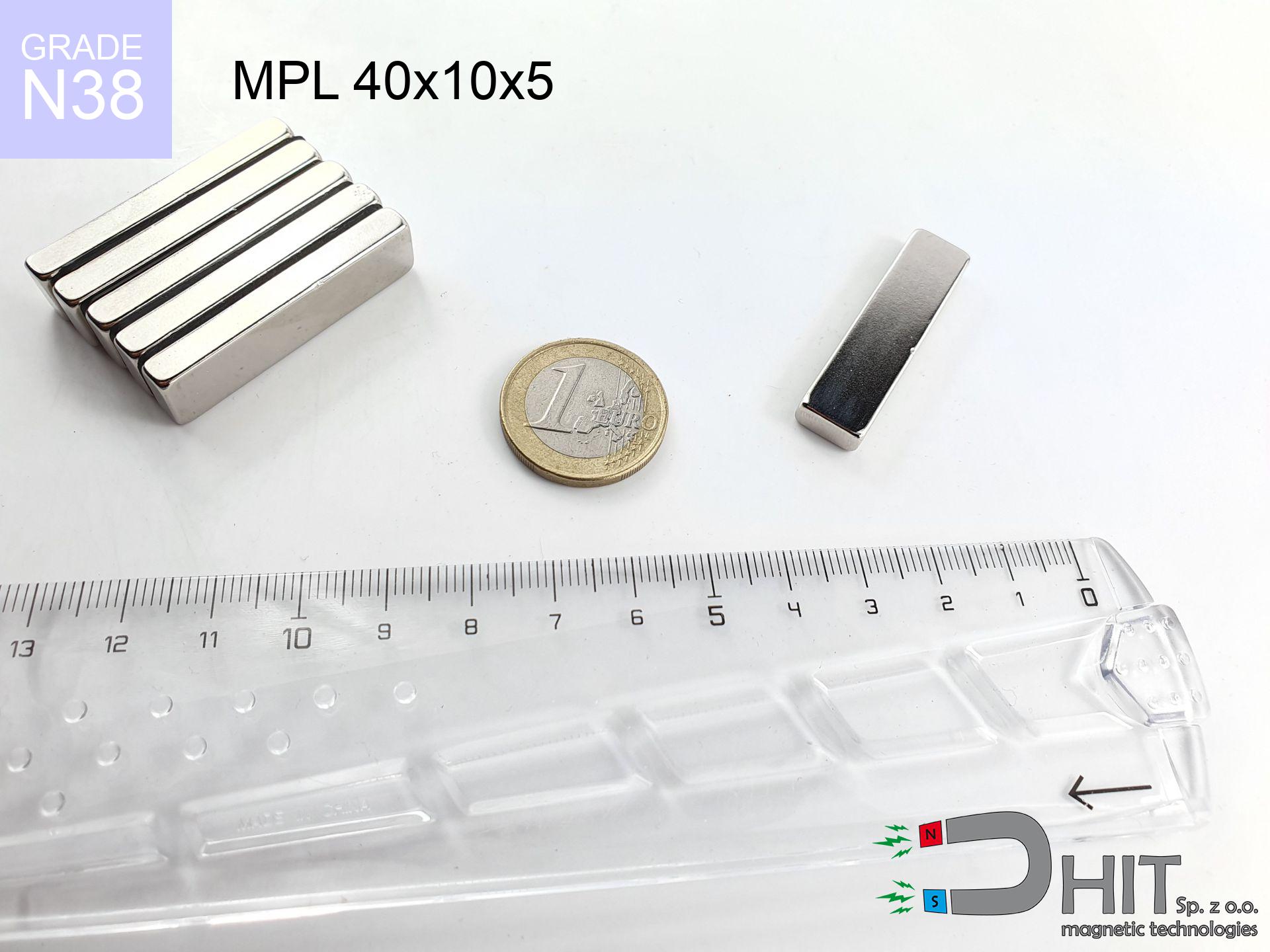
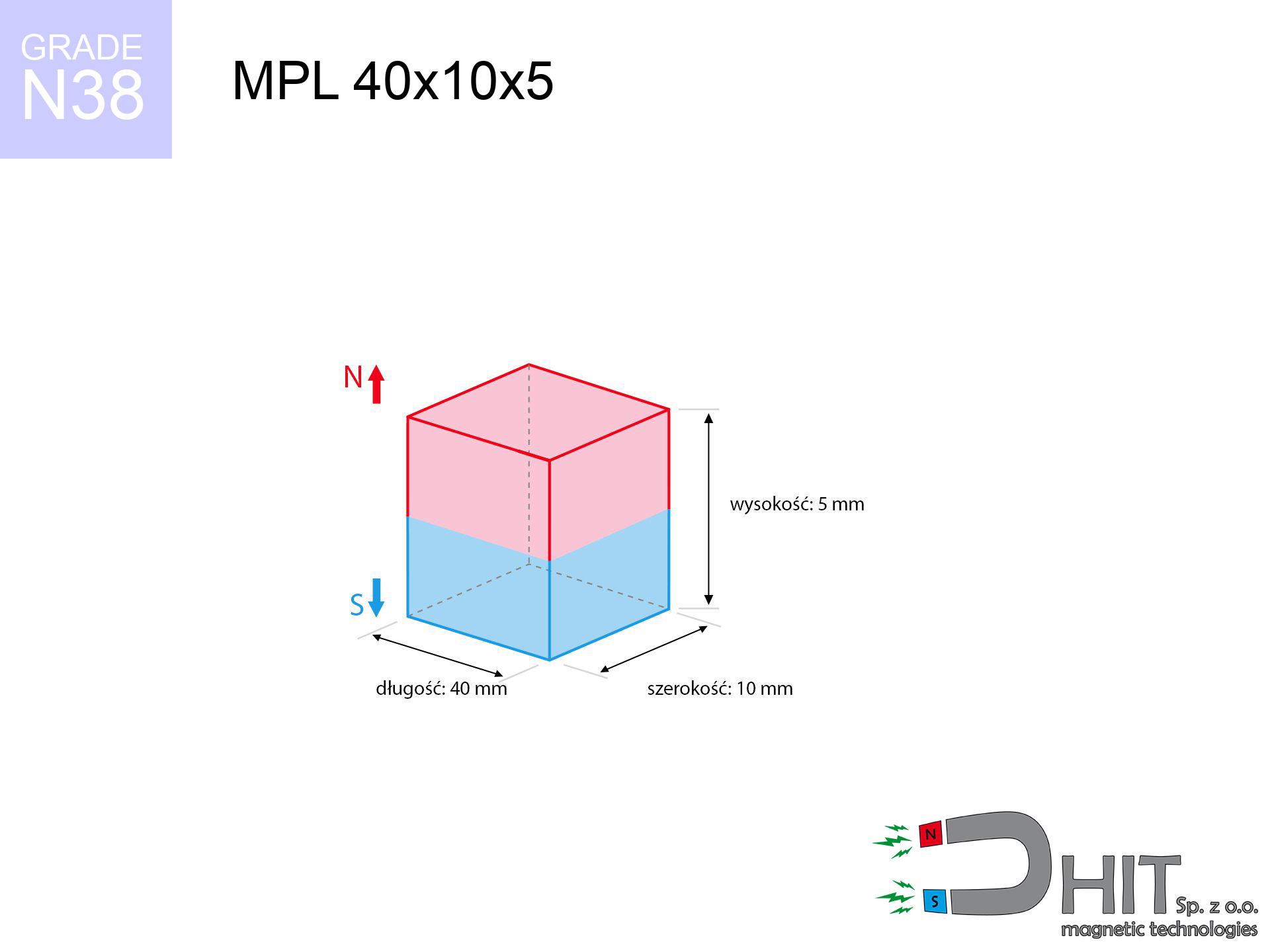
MPL 40x10x5 / N38 - lamellar magnet
lamellar magnet
Catalog no 020152
GTIN/EAN: 5906301811589
- length
- 40 mm [±0,1 mm]
- Width
- 10 mm [±0,1 mm]
- Height
- 5 mm [±0,1 mm]
- Weight
- 15 g
- Magnetization Direction
- ↑ axial
- Coating
- [NiCuNi] Nickel
6.03 zł with VAT / pcs + price for transport
4.90 zł net + 23% VAT / pcs
bulk discounts:
Need more?Engineering report for this magnet
Full PDF analysis: pull and shear force, effect of distance, temperature and plate thickness, safety distances and the demagnetization curve.
Give us a call
+48 888 99 98 98
otherwise contact us via
request form
through our site.
Weight as well as appearance of magnets can be verified using our
magnetic mass calculator.
Same-day processing for orders placed before 14:00.
Technical details - MPL 40x10x5 / N38 - lamellar magnet
Specification / characteristics - MPL 40x10x5 / N38 - lamellar magnet
| properties | values |
|---|---|
| Cat. no. | 020152 |
| GTIN/EAN | 5906301811589 |
| Production/Distribution | Dhit sp. z o.o. |
| Country of origin | Poland / China / Germany |
| Customs code | 85059029 |
| length | 40 mm [±0,1 mm] |
| Width | 10 mm [±0,1 mm] |
| Height | 5 mm [±0,1 mm] |
| Weight | 15 g |
| Magnetization Direction | ↑ axial |
| Load capacity ~ ? | 11.85 kg / 116.27 N |
| Magnetic Induction ~ ? | 321.37 mT / 3214 Gs |
| Coating | [NiCuNi] Nickel |
| Manufacturing Tolerance | ±0.1 mm |
Magnetic properties of material N38
| properties | values | units |
|---|---|---|
| remenance Br [min. - max.] ? | 12.2-12.6 | kGs |
| remenance Br [min. - max.] ? | 1220-1260 | mT |
| coercivity bHc ? | 10.8-11.5 | kOe |
| coercivity bHc ? | 860-915 | kA/m |
| actual internal force iHc | ≥ 12 | kOe |
| actual internal force iHc | ≥ 955 | kA/m |
| energy density [min. - max.] ? | 36-38 | BH max MGOe |
| energy density [min. - max.] ? | 287-303 | BH max KJ/m |
| max. temperature ? | ≤ 80 | °C |
Physical properties of sintered neodymium magnets Nd2Fe14B at 20°C
| properties | values | units |
|---|---|---|
| Vickers hardness | ≥550 | Hv |
| Density | ≥7.4 | g/cm3 |
| Curie Temperature TC | 312 - 380 | °C |
| Curie Temperature TF | 593 - 716 | °F |
| Specific resistance | 150 | μΩ⋅cm |
| Bending strength | 250 | MPa |
| Compressive strength | 1000~1100 | MPa |
| Thermal expansion parallel (∥) to orientation (M) | (3-4) x 10-6 | °C-1 |
| Thermal expansion perpendicular (⊥) to orientation (M) | -(1-3) x 10-6 | °C-1 |
| Young's modulus | 1.7 x 10⁴ | kg/mm² |
Physical modeling of the product - report
These values represent the result of a mathematical analysis. Results were calculated on models for the class Nd2Fe14B. Real-world performance might slightly differ from theoretical values. Please consider these calculations as a supplementary guide when designing systems.
Table 1: Static force (pull vs gap) - power drop
MPL 40x10x5 / N38
| Distance (mm) | Induction (Gauss) / mT | Pull Force (kg/lbs/g/N) | Risk Status |
|---|---|---|---|
| 0 mm |
3212 Gs
321.2 mT
|
11.85 kg / 26.12 pounds
11850.0 g / 116.2 N
|
crushing |
| 1 mm |
2791 Gs
279.1 mT
|
8.95 kg / 19.73 pounds
8947.7 g / 87.8 N
|
warning |
| 2 mm |
2358 Gs
235.8 mT
|
6.38 kg / 14.08 pounds
6384.9 g / 62.6 N
|
warning |
| 3 mm |
1965 Gs
196.5 mT
|
4.43 kg / 9.77 pounds
4432.4 g / 43.5 N
|
warning |
| 5 mm |
1360 Gs
136.0 mT
|
2.12 kg / 4.68 pounds
2122.9 g / 20.8 N
|
warning |
| 10 mm |
615 Gs
61.5 mT
|
0.43 kg / 0.96 pounds
434.1 g / 4.3 N
|
safe |
| 15 mm |
329 Gs
32.9 mT
|
0.12 kg / 0.27 pounds
124.5 g / 1.2 N
|
safe |
| 20 mm |
195 Gs
19.5 mT
|
0.04 kg / 0.10 pounds
43.9 g / 0.4 N
|
safe |
| 30 mm |
83 Gs
8.3 mT
|
0.01 kg / 0.02 pounds
8.0 g / 0.1 N
|
safe |
| 50 mm |
24 Gs
2.4 mT
|
0.00 kg / 0.00 pounds
0.6 g / 0.0 N
|
safe |
Table 2: Vertical load (wall)
MPL 40x10x5 / N38
| Distance (mm) | Friction coefficient | Pull Force (kg/lbs/g/N) |
|---|---|---|
| 0 mm | Stal (~0.2) |
2.37 kg / 5.22 pounds
2370.0 g / 23.2 N
|
| 1 mm | Stal (~0.2) |
1.79 kg / 3.95 pounds
1790.0 g / 17.6 N
|
| 2 mm | Stal (~0.2) |
1.28 kg / 2.81 pounds
1276.0 g / 12.5 N
|
| 3 mm | Stal (~0.2) |
0.89 kg / 1.95 pounds
886.0 g / 8.7 N
|
| 5 mm | Stal (~0.2) |
0.42 kg / 0.93 pounds
424.0 g / 4.2 N
|
| 10 mm | Stal (~0.2) |
0.09 kg / 0.19 pounds
86.0 g / 0.8 N
|
| 15 mm | Stal (~0.2) |
0.02 kg / 0.05 pounds
24.0 g / 0.2 N
|
| 20 mm | Stal (~0.2) |
0.01 kg / 0.02 pounds
8.0 g / 0.1 N
|
| 30 mm | Stal (~0.2) |
0.00 kg / 0.00 pounds
2.0 g / 0.0 N
|
| 50 mm | Stal (~0.2) |
0.00 kg / 0.00 pounds
0.0 g / 0.0 N
|
Table 3: Vertical assembly (shearing) - vertical pull
MPL 40x10x5 / N38
| Surface type | Friction coefficient / % Mocy | Max load (kg/lbs/g/N) |
|---|---|---|
| Raw steel |
µ = 0.3
30% Nominalnej Siły
|
3.55 kg / 7.84 pounds
3555.0 g / 34.9 N
|
| Painted steel (standard) |
µ = 0.2
20% Nominalnej Siły
|
2.37 kg / 5.22 pounds
2370.0 g / 23.2 N
|
| Oily/slippery steel |
µ = 0.1
10% Nominalnej Siły
|
1.19 kg / 2.61 pounds
1185.0 g / 11.6 N
|
| Magnet with anti-slip rubber |
µ = 0.5
50% Nominalnej Siły
|
5.93 kg / 13.06 pounds
5925.0 g / 58.1 N
|
Table 4: Steel thickness (saturation) - sheet metal selection
MPL 40x10x5 / N38
| Steel thickness (mm) | % power | Real pull force (kg/lbs/g/N) |
|---|---|---|
| 0.5 mm |
|
0.59 kg / 1.31 pounds
592.5 g / 5.8 N
|
| 1 mm |
|
1.48 kg / 3.27 pounds
1481.3 g / 14.5 N
|
| 2 mm |
|
2.96 kg / 6.53 pounds
2962.5 g / 29.1 N
|
| 3 mm |
|
4.44 kg / 9.80 pounds
4443.8 g / 43.6 N
|
| 5 mm |
|
7.41 kg / 16.33 pounds
7406.3 g / 72.7 N
|
| 10 mm |
|
11.85 kg / 26.12 pounds
11850.0 g / 116.2 N
|
| 11 mm |
|
11.85 kg / 26.12 pounds
11850.0 g / 116.2 N
|
| 12 mm |
|
11.85 kg / 26.12 pounds
11850.0 g / 116.2 N
|
Table 5: Working in heat (material behavior) - resistance threshold
MPL 40x10x5 / N38
| Ambient temp. (°C) | Power loss | Remaining pull (kg/lbs/g/N) | Status |
|---|---|---|---|
| 20 °C | 0.0% |
11.85 kg / 26.12 pounds
11850.0 g / 116.2 N
|
OK |
| 40 °C | -2.2% |
11.59 kg / 25.55 pounds
11589.3 g / 113.7 N
|
OK |
| 60 °C | -4.4% |
11.33 kg / 24.98 pounds
11328.6 g / 111.1 N
|
|
| 80 °C | -6.6% |
11.07 kg / 24.40 pounds
11067.9 g / 108.6 N
|
|
| 100 °C | -28.8% |
8.44 kg / 18.60 pounds
8437.2 g / 82.8 N
|
Table 6: Magnet-Magnet interaction (attraction) - forces in the system
MPL 40x10x5 / N38
| Gap (mm) | Attraction (kg/lbs) (N-S) | Shear Force (kg/lbs/g/N) | Repulsion (kg/lbs) (N-N) |
|---|---|---|---|
| 0 mm |
25.44 kg / 56.10 pounds
4 569 Gs
|
3.82 kg / 8.41 pounds
3817 g / 37.4 N
|
N/A |
| 1 mm |
22.33 kg / 49.22 pounds
6 018 Gs
|
3.35 kg / 7.38 pounds
3349 g / 32.9 N
|
20.09 kg / 44.30 pounds
~0 Gs
|
| 2 mm |
19.21 kg / 42.36 pounds
5 582 Gs
|
2.88 kg / 6.35 pounds
2882 g / 28.3 N
|
17.29 kg / 38.12 pounds
~0 Gs
|
| 3 mm |
16.31 kg / 35.96 pounds
5 144 Gs
|
2.45 kg / 5.39 pounds
2447 g / 24.0 N
|
14.68 kg / 32.36 pounds
~0 Gs
|
| 5 mm |
11.45 kg / 25.23 pounds
4 309 Gs
|
1.72 kg / 3.78 pounds
1717 g / 16.8 N
|
10.30 kg / 22.71 pounds
~0 Gs
|
| 10 mm |
4.56 kg / 10.05 pounds
2 719 Gs
|
0.68 kg / 1.51 pounds
684 g / 6.7 N
|
4.10 kg / 9.04 pounds
~0 Gs
|
| 20 mm |
0.93 kg / 2.05 pounds
1 230 Gs
|
0.14 kg / 0.31 pounds
140 g / 1.4 N
|
0.84 kg / 1.85 pounds
~0 Gs
|
| 50 mm |
0.04 kg / 0.08 pounds
249 Gs
|
0.01 kg / 0.01 pounds
6 g / 0.1 N
|
0.03 kg / 0.08 pounds
~0 Gs
|
| 60 mm |
0.02 kg / 0.04 pounds
167 Gs
|
0.00 kg / 0.01 pounds
3 g / 0.0 N
|
0.02 kg / 0.03 pounds
~0 Gs
|
| 70 mm |
0.01 kg / 0.02 pounds
116 Gs
|
0.00 kg / 0.00 pounds
1 g / 0.0 N
|
0.00 kg / 0.00 pounds
~0 Gs
|
| 80 mm |
0.00 kg / 0.01 pounds
84 Gs
|
0.00 kg / 0.00 pounds
1 g / 0.0 N
|
0.00 kg / 0.00 pounds
~0 Gs
|
| 90 mm |
0.00 kg / 0.01 pounds
62 Gs
|
0.00 kg / 0.00 pounds
0 g / 0.0 N
|
0.00 kg / 0.00 pounds
~0 Gs
|
| 100 mm |
0.00 kg / 0.00 pounds
48 Gs
|
0.00 kg / 0.00 pounds
0 g / 0.0 N
|
0.00 kg / 0.00 pounds
~0 Gs
|
Table 7: Hazards (implants) - warnings
MPL 40x10x5 / N38
| Object / Device | Limit (Gauss) / mT | Safe distance |
|---|---|---|
| Pacemaker | 5 Gs (0.5 mT) | 9.0 cm |
| Hearing aid | 10 Gs (1.0 mT) | 7.0 cm |
| Mechanical watch | 20 Gs (2.0 mT) | 5.5 cm |
| Mobile device | 40 Gs (4.0 mT) | 4.5 cm |
| Car key | 50 Gs (5.0 mT) | 4.0 cm |
| Payment card | 400 Gs (40.0 mT) | 1.5 cm |
| HDD hard drive | 600 Gs (60.0 mT) | 1.5 cm |
Table 8: Collisions (cracking risk) - collision effects
MPL 40x10x5 / N38
| Start from (mm) | Speed (km/h) | Energy (J) | Predicted outcome |
|---|---|---|---|
| 10 mm |
24.30 km/h
(6.75 m/s)
|
0.34 J | |
| 30 mm |
24.92 km/h
(6.92 m/s)
|
0.36 J | |
| 50 mm |
24.93 km/h
(6.92 m/s)
|
0.36 J | |
| 100 mm |
24.94 km/h
(6.93 m/s)
|
0.36 J |
Table 9: Anti-corrosion coating durability
MPL 40x10x5 / N38
| Technical parameter | Value / Description |
|---|---|
| Coating type | [NiCuNi] Nickel |
| Layer structure | Nickel - Copper - Nickel |
| Layer thickness | 10-20 µm |
| Salt spray test (SST) ? | 24 h |
| Recommended environment | Indoors only (dry) |
Table 10: Construction data (Pc)
MPL 40x10x5 / N38
| Parameter | Value | SI Unit / Description |
|---|---|---|
| Magnetic Flux | 11 419 Mx | 114.2 µWb |
| Pc Coefficient | 0.31 | Low (Flat) |
Table 11: Underwater work (magnet fishing)
MPL 40x10x5 / N38
| Environment | Effective steel pull | Effect |
|---|---|---|
| Air (land) | 11.85 kg | Standard |
| Water (riverbed) |
13.57 kg
(+1.72 kg buoyancy gain)
|
+14.5% |
1. Sliding resistance
*Note: On a vertical wall, the magnet holds merely ~20% of its nominal pull.
2. Plate thickness effect
*Thin steel (e.g. computer case) significantly reduces the holding force.
3. Power loss vs temp
*For N38 grade, the max working temp is 80°C.
4. Demagnetization curve and operating point (B-H)
chart generated for the permeance coefficient Pc (Permeance Coefficient) = 0.31
The chart above illustrates the magnetic characteristics of the material within the second quadrant of the hysteresis loop. The solid red line represents the demagnetization curve (material potential), while the dashed blue line is the load line based on the magnet's geometry. The Pc (Permeance Coefficient), also known as the load line slope, is a dimensionless value that describes the relationship between the magnet's shape and its magnetic stability. The intersection of these two lines (the black dot) is the operating point — it determines the actual magnetic flux density generated by the magnet in this specific configuration. A higher Pc value means the magnet is more 'slender' (tall relative to its area), resulting in a higher operating point and better resistance to irreversible demagnetization caused by external fields or temperature. A value of 0.42 is relatively low (typical for flat magnets), meaning the operating point is closer to the 'knee' of the curve — caution is advised when operating at temperatures near the maximum limit to avoid strength loss.
Material specification
| iron (Fe) | 64% – 68% |
| neodymium (Nd) | 29% – 32% |
| boron (B) | 1.1% – 1.2% |
| dysprosium (Dy) | 0.5% – 2.0% |
| coating (Ni-Cu-Ni) | < 0.05% |
Environmental data
| recyclability (EoL) | 100% |
| recycled raw materials | ~10% (pre-cons) |
| carbon footprint | low / zredukowany |
| waste code (EWC) | 16 02 16 |
See more products
![SM 32x200 [2xM8] / N42 - magnetic separator](https://cdn3.dhit.pl/graphics/products/sm-32x200-2xm8-fub.jpg "SM 32x200 [2xM8] / N42 - magnetic separator")


Pros as well as cons of neodymium magnets.
Pros
- They do not lose power, even after nearly ten years – the drop in lifting capacity is only ~1% (according to tests),
- They are noted for resistance to demagnetization induced by external magnetic fields,
- By applying a lustrous coating of gold, the element acquires an aesthetic look,
- The surface of neodymium magnets generates a unique magnetic field – this is a distinguishing feature,
- Due to their durability and thermal resistance, neodymium magnets can operate (depending on the form) even at high temperatures reaching 230°C or more...
- Thanks to freedom in designing and the ability to modify to client solutions,
- Versatile presence in advanced technology sectors – they are utilized in computer drives, electromotive mechanisms, advanced medical instruments, as well as complex engineering applications.
- Thanks to concentrated force, small magnets offer high operating force, in miniature format,
Weaknesses
- To avoid cracks upon strong impacts, we suggest using special steel housings. Such a solution protects the magnet and simultaneously improves its durability.
- Neodymium magnets decrease their force under the influence of heating. As soon as 80°C is exceeded, many of them start losing their force. Therefore, we recommend our special magnets marked [AH], which maintain stability even at temperatures up to 230°C
- When exposed to humidity, magnets start to rust. To use them in conditions outside, it is recommended to use protective magnets, such as those in rubber or plastics, which secure oxidation as well as corrosion.
- Limited possibility of making nuts in the magnet and complicated shapes - recommended is a housing - mounting mechanism.
- Health risk to health – tiny shards of magnets are risky, in case of ingestion, which gains importance in the context of child health protection. It is also worth noting that tiny parts of these products are able to disrupt the diagnostic process medical when they are in the body.
- Higher cost of purchase is a significant factor to consider compared to ceramic magnets, especially in budget applications
Pull force analysis
Optimal lifting capacity of a neodymium magnet – what contributes to it?
- using a sheet made of mild steel, functioning as a magnetic yoke
- possessing a thickness of at least 10 mm to avoid saturation
- with an polished touching surface
- without any insulating layer between the magnet and steel
- for force applied at a right angle (pull-off, not shear)
- in stable room temperature
Practical lifting capacity: influencing factors
- Gap between magnet and steel – every millimeter of distance (caused e.g. by varnish or dirt) diminishes the magnet efficiency, often by half at just 0.5 mm.
- Loading method – catalog parameter refers to detachment vertically. When attempting to slide, the magnet holds significantly lower power (typically approx. 20-30% of nominal force).
- Base massiveness – too thin sheet does not close the flux, causing part of the power to be lost to the other side.
- Material composition – not every steel reacts the same. Alloy additives weaken the attraction effect.
- Surface finish – ideal contact is possible only on smooth steel. Rough texture create air cushions, weakening the magnet.
- Temperature – temperature increase causes a temporary drop of force. It is worth remembering the maximum operating temperature for a given model.
Holding force was tested on the plate surface of 20 mm thickness, when a perpendicular force was applied, whereas under shearing force the lifting capacity is smaller. In addition, even a small distance between the magnet’s surface and the plate decreases the holding force.
H&S for magnets
Magnetic media
Equipment safety: Neodymium magnets can damage data carriers and delicate electronics (heart implants, hearing aids, mechanical watches).
Medical interference
Warning for patients: Strong magnetic fields disrupt medical devices. Keep at least 30 cm distance or request help to handle the magnets.
Phone sensors
Navigation devices and mobile phones are extremely susceptible to magnetic fields. Close proximity with a powerful NdFeB magnet can decalibrate the sensors in your phone.
Combustion hazard
Dust generated during machining of magnets is flammable. Avoid drilling into magnets unless you are an expert.
Adults only
Product intended for adults. Tiny parts pose a choking risk, leading to serious injuries. Keep away from kids and pets.
Respect the power
Before starting, check safety instructions. Uncontrolled attraction can break the magnet or injure your hand. Be predictive.
Nickel allergy
Nickel alert: The nickel-copper-nickel coating contains nickel. If an allergic reaction happens, cease handling magnets and wear gloves.
Permanent damage
Monitor thermal conditions. Exposing the magnet to high heat will destroy its properties and strength.
Eye protection
Neodymium magnets are sintered ceramics, which means they are very brittle. Collision of two magnets will cause them breaking into small pieces.
Hand protection
Danger of trauma: The pulling power is so immense that it can cause hematomas, crushing, and broken bones. Protective gloves are recommended.
Tabela kosztu i czasu dostawy
Płatność przed wysyłką:

GLS kurier
Przesyłka będzie u Ciebie za 2-3 dni
14.99 ZŁ

InPost Paczkomaty 24/7
Przesyłka będzie u Ciebie za 1-2 dni
12.30 ZŁ
Płatność przy odbiorze (pobranie):
GLS kurier
Przesyłka będzie u Ciebie za 1-2 dni
23.00 ZŁ
Rate the product
Your rating