
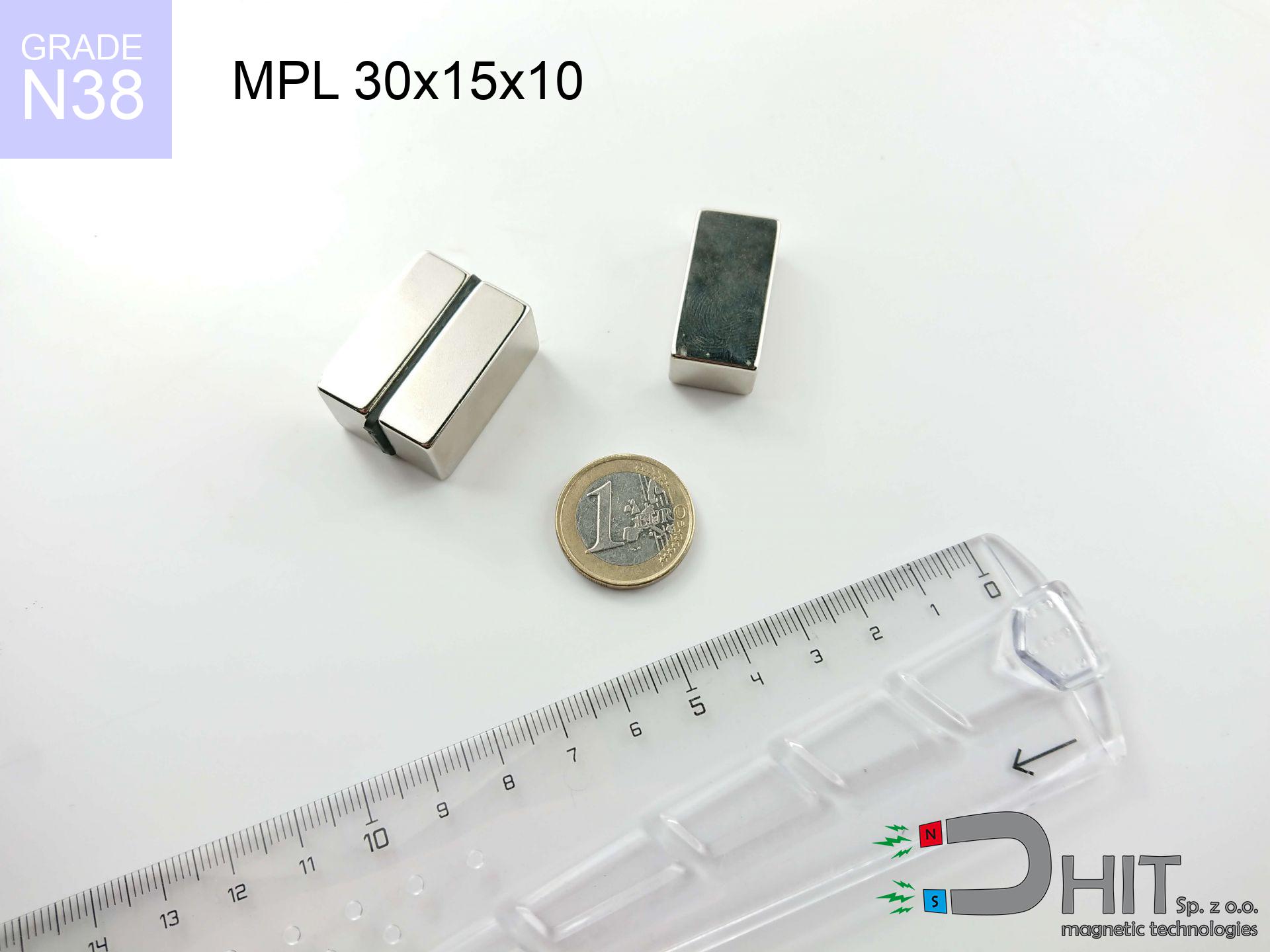
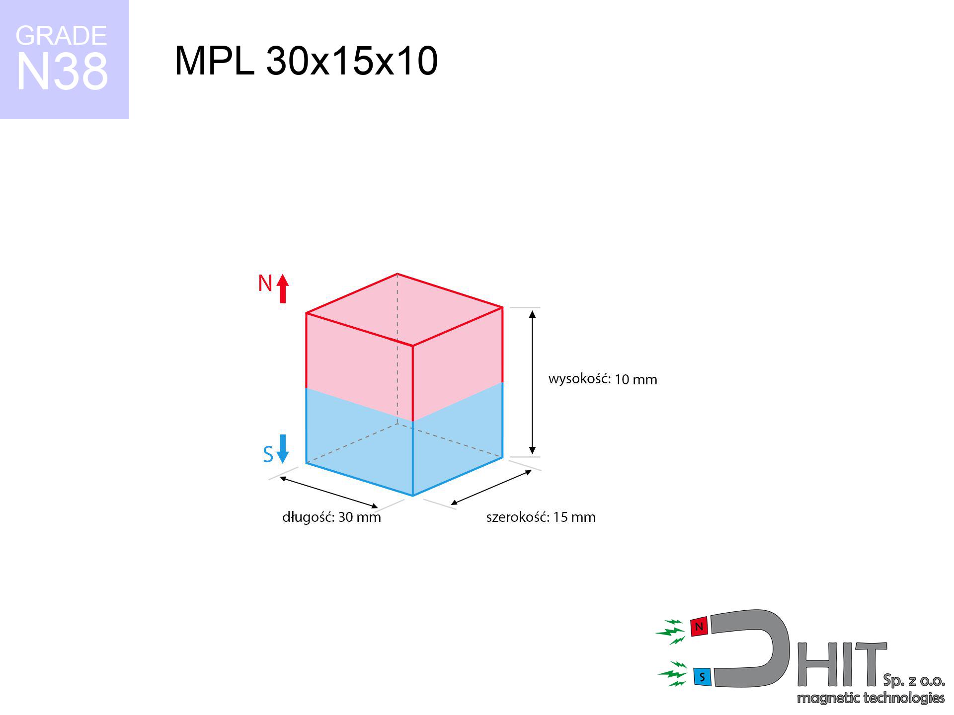
MPL 30x15x10 / N38 - lamellar magnet
lamellar magnet
Catalog no 020389
GTIN/EAN: 5906301811886
length
30 mm [±0,1 mm]
Width
15 mm [±0,1 mm]
Height
10 mm [±0,1 mm]
Weight
33.75 g
Magnetization Direction
↑ axial
Load capacity
16.84 kg / 165.22 N
Magnetic Induction
413.45 mT / 4135 Gs
Coating
[NiCuNi] Nickel
24.48 ZŁ with VAT / pcs + price for transport
19.90 ZŁ net + 23% VAT / pcs
bulk discounts:
Need more?
Give us a call
+48 22 499 98 98
alternatively let us know through
contact form
our website.
Lifting power and structure of a magnet can be verified on our
modular calculator.
Same-day shipping for orders placed before 14:00.
Technical of the product - MPL 30x15x10 / N38 - lamellar magnet
Specification / characteristics - MPL 30x15x10 / N38 - lamellar magnet
| properties | values |
|---|---|
| Cat. no. | 020389 |
| GTIN/EAN | 5906301811886 |
| Production/Distribution | Dhit sp. z o.o. |
| Country of origin | Poland / China / Germany |
| Customs code | 85059029 |
| length | 30 mm [±0,1 mm] |
| Width | 15 mm [±0,1 mm] |
| Height | 10 mm [±0,1 mm] |
| Weight | 33.75 g |
| Magnetization Direction | ↑ axial |
| Load capacity ~ ? | 16.84 kg / 165.22 N |
| Magnetic Induction ~ ? | 413.45 mT / 4135 Gs |
| Coating | [NiCuNi] Nickel |
| Manufacturing Tolerance | ±0.1 mm |
Magnetic properties of material N38
| properties | values | units |
|---|---|---|
| remenance Br [min. - max.] ? | 12.2-12.6 | kGs |
| remenance Br [min. - max.] ? | 1220-1260 | mT |
| coercivity bHc ? | 10.8-11.5 | kOe |
| coercivity bHc ? | 860-915 | kA/m |
| actual internal force iHc | ≥ 12 | kOe |
| actual internal force iHc | ≥ 955 | kA/m |
| energy density [min. - max.] ? | 36-38 | BH max MGOe |
| energy density [min. - max.] ? | 287-303 | BH max KJ/m |
| max. temperature ? | ≤ 80 | °C |
Physical properties of sintered neodymium magnets Nd2Fe14B at 20°C
| properties | values | units |
|---|---|---|
| Vickers hardness | ≥550 | Hv |
| Density | ≥7.4 | g/cm3 |
| Curie Temperature TC | 312 - 380 | °C |
| Curie Temperature TF | 593 - 716 | °F |
| Specific resistance | 150 | μΩ⋅cm |
| Bending strength | 250 | MPa |
| Compressive strength | 1000~1100 | MPa |
| Thermal expansion parallel (∥) to orientation (M) | (3-4) x 10-6 | °C-1 |
| Thermal expansion perpendicular (⊥) to orientation (M) | -(1-3) x 10-6 | °C-1 |
| Young's modulus | 1.7 x 10⁴ | kg/mm² |
Engineering simulation of the product - data
Presented information are the result of a mathematical simulation. Results were calculated on algorithms for the material Nd2Fe14B. Actual conditions may deviate from the simulation results. Use these calculations as a preliminary roadmap during assembly planning.
Table 1: Static force (pull vs gap) - characteristics
MPL 30x15x10 / N38
| Distance (mm) | Induction (Gauss) / mT | Pull Force (kg/lbs/g/N) | Risk Status |
|---|---|---|---|
| 0 mm |
4133 Gs
413.3 mT
|
16.84 kg / 37.13 pounds
16840.0 g / 165.2 N
|
critical level |
| 1 mm |
3754 Gs
375.4 mT
|
13.89 kg / 30.62 pounds
13889.5 g / 136.3 N
|
critical level |
| 2 mm |
3365 Gs
336.5 mT
|
11.16 kg / 24.60 pounds
11159.2 g / 109.5 N
|
critical level |
| 3 mm |
2988 Gs
298.8 mT
|
8.80 kg / 19.41 pounds
8803.6 g / 86.4 N
|
warning |
| 5 mm |
2321 Gs
232.1 mT
|
5.31 kg / 11.71 pounds
5309.9 g / 52.1 N
|
warning |
| 10 mm |
1225 Gs
122.5 mT
|
1.48 kg / 3.26 pounds
1480.1 g / 14.5 N
|
safe |
| 15 mm |
684 Gs
68.4 mT
|
0.46 kg / 1.02 pounds
461.6 g / 4.5 N
|
safe |
| 20 mm |
409 Gs
40.9 mT
|
0.16 kg / 0.36 pounds
164.8 g / 1.6 N
|
safe |
| 30 mm |
173 Gs
17.3 mT
|
0.03 kg / 0.07 pounds
29.6 g / 0.3 N
|
safe |
| 50 mm |
50 Gs
5.0 mT
|
0.00 kg / 0.01 pounds
2.4 g / 0.0 N
|
safe |
Table 2: Sliding capacity (wall)
MPL 30x15x10 / N38
| Distance (mm) | Friction coefficient | Pull Force (kg/lbs/g/N) |
|---|---|---|
| 0 mm | Stal (~0.2) |
3.37 kg / 7.43 pounds
3368.0 g / 33.0 N
|
| 1 mm | Stal (~0.2) |
2.78 kg / 6.12 pounds
2778.0 g / 27.3 N
|
| 2 mm | Stal (~0.2) |
2.23 kg / 4.92 pounds
2232.0 g / 21.9 N
|
| 3 mm | Stal (~0.2) |
1.76 kg / 3.88 pounds
1760.0 g / 17.3 N
|
| 5 mm | Stal (~0.2) |
1.06 kg / 2.34 pounds
1062.0 g / 10.4 N
|
| 10 mm | Stal (~0.2) |
0.30 kg / 0.65 pounds
296.0 g / 2.9 N
|
| 15 mm | Stal (~0.2) |
0.09 kg / 0.20 pounds
92.0 g / 0.9 N
|
| 20 mm | Stal (~0.2) |
0.03 kg / 0.07 pounds
32.0 g / 0.3 N
|
| 30 mm | Stal (~0.2) |
0.01 kg / 0.01 pounds
6.0 g / 0.1 N
|
| 50 mm | Stal (~0.2) |
0.00 kg / 0.00 pounds
0.0 g / 0.0 N
|
Table 3: Wall mounting (sliding) - vertical pull
MPL 30x15x10 / N38
| Surface type | Friction coefficient / % Mocy | Max load (kg/lbs/g/N) |
|---|---|---|
| Raw steel |
µ = 0.3
30% Nominalnej Siły
|
5.05 kg / 11.14 pounds
5052.0 g / 49.6 N
|
| Painted steel (standard) |
µ = 0.2
20% Nominalnej Siły
|
3.37 kg / 7.43 pounds
3368.0 g / 33.0 N
|
| Oily/slippery steel |
µ = 0.1
10% Nominalnej Siły
|
1.68 kg / 3.71 pounds
1684.0 g / 16.5 N
|
| Magnet with anti-slip rubber |
µ = 0.5
50% Nominalnej Siły
|
8.42 kg / 18.56 pounds
8420.0 g / 82.6 N
|
Table 4: Material efficiency (substrate influence) - power losses
MPL 30x15x10 / N38
| Steel thickness (mm) | % power | Real pull force (kg/lbs/g/N) |
|---|---|---|
| 0.5 mm |
|
0.84 kg / 1.86 pounds
842.0 g / 8.3 N
|
| 1 mm |
|
2.11 kg / 4.64 pounds
2105.0 g / 20.7 N
|
| 2 mm |
|
4.21 kg / 9.28 pounds
4210.0 g / 41.3 N
|
| 3 mm |
|
6.31 kg / 13.92 pounds
6315.0 g / 62.0 N
|
| 5 mm |
|
10.53 kg / 23.20 pounds
10525.0 g / 103.3 N
|
| 10 mm |
|
16.84 kg / 37.13 pounds
16840.0 g / 165.2 N
|
| 11 mm |
|
16.84 kg / 37.13 pounds
16840.0 g / 165.2 N
|
| 12 mm |
|
16.84 kg / 37.13 pounds
16840.0 g / 165.2 N
|
Table 5: Thermal resistance (stability) - power drop
MPL 30x15x10 / N38
| Ambient temp. (°C) | Power loss | Remaining pull (kg/lbs/g/N) | Status |
|---|---|---|---|
| 20 °C | 0.0% |
16.84 kg / 37.13 pounds
16840.0 g / 165.2 N
|
OK |
| 40 °C | -2.2% |
16.47 kg / 36.31 pounds
16469.5 g / 161.6 N
|
OK |
| 60 °C | -4.4% |
16.10 kg / 35.49 pounds
16099.0 g / 157.9 N
|
|
| 80 °C | -6.6% |
15.73 kg / 34.68 pounds
15728.6 g / 154.3 N
|
|
| 100 °C | -28.8% |
11.99 kg / 26.43 pounds
11990.1 g / 117.6 N
|
Table 6: Magnet-Magnet interaction (repulsion) - forces in the system
MPL 30x15x10 / N38
| Gap (mm) | Attraction (kg/lbs) (N-S) | Shear Force (kg/lbs/g/N) | Repulsion (kg/lbs) (N-N) |
|---|---|---|---|
| 0 mm |
47.39 kg / 104.48 pounds
5 357 Gs
|
7.11 kg / 15.67 pounds
7109 g / 69.7 N
|
N/A |
| 1 mm |
43.23 kg / 95.30 pounds
7 895 Gs
|
6.48 kg / 14.29 pounds
6484 g / 63.6 N
|
38.90 kg / 85.77 pounds
~0 Gs
|
| 2 mm |
39.09 kg / 86.17 pounds
7 507 Gs
|
5.86 kg / 12.93 pounds
5863 g / 57.5 N
|
35.18 kg / 77.56 pounds
~0 Gs
|
| 3 mm |
35.13 kg / 77.45 pounds
7 117 Gs
|
5.27 kg / 11.62 pounds
5270 g / 51.7 N
|
31.62 kg / 69.70 pounds
~0 Gs
|
| 5 mm |
27.95 kg / 61.61 pounds
6 348 Gs
|
4.19 kg / 9.24 pounds
4192 g / 41.1 N
|
25.15 kg / 55.45 pounds
~0 Gs
|
| 10 mm |
14.94 kg / 32.94 pounds
4 642 Gs
|
2.24 kg / 4.94 pounds
2242 g / 22.0 N
|
13.45 kg / 29.65 pounds
~0 Gs
|
| 20 mm |
4.17 kg / 9.18 pounds
2 451 Gs
|
0.62 kg / 1.38 pounds
625 g / 6.1 N
|
3.75 kg / 8.26 pounds
~0 Gs
|
| 50 mm |
0.19 kg / 0.41 pounds
519 Gs
|
0.03 kg / 0.06 pounds
28 g / 0.3 N
|
0.17 kg / 0.37 pounds
~0 Gs
|
| 60 mm |
0.08 kg / 0.18 pounds
347 Gs
|
0.01 kg / 0.03 pounds
13 g / 0.1 N
|
0.08 kg / 0.17 pounds
~0 Gs
|
| 70 mm |
0.04 kg / 0.09 pounds
242 Gs
|
0.01 kg / 0.01 pounds
6 g / 0.1 N
|
0.04 kg / 0.08 pounds
~0 Gs
|
| 80 mm |
0.02 kg / 0.05 pounds
175 Gs
|
0.00 kg / 0.01 pounds
3 g / 0.0 N
|
0.02 kg / 0.04 pounds
~0 Gs
|
| 90 mm |
0.01 kg / 0.03 pounds
130 Gs
|
0.00 kg / 0.00 pounds
2 g / 0.0 N
|
0.01 kg / 0.02 pounds
~0 Gs
|
| 100 mm |
0.01 kg / 0.02 pounds
99 Gs
|
0.00 kg / 0.00 pounds
1 g / 0.0 N
|
0.00 kg / 0.00 pounds
~0 Gs
|
Table 7: Safety (HSE) (implants) - precautionary measures
MPL 30x15x10 / N38
| Object / Device | Limit (Gauss) / mT | Safe distance |
|---|---|---|
| Pacemaker | 5 Gs (0.5 mT) | 12.0 cm |
| Hearing aid | 10 Gs (1.0 mT) | 9.5 cm |
| Timepiece | 20 Gs (2.0 mT) | 7.5 cm |
| Mobile device | 40 Gs (4.0 mT) | 5.5 cm |
| Remote | 50 Gs (5.0 mT) | 5.0 cm |
| Payment card | 400 Gs (40.0 mT) | 2.5 cm |
| HDD hard drive | 600 Gs (60.0 mT) | 2.0 cm |
Table 8: Impact energy (cracking risk) - warning
MPL 30x15x10 / N38
| Start from (mm) | Speed (km/h) | Energy (J) | Predicted outcome |
|---|---|---|---|
| 10 mm |
23.73 km/h
(6.59 m/s)
|
0.73 J | |
| 30 mm |
39.06 km/h
(10.85 m/s)
|
1.99 J | |
| 50 mm |
50.38 km/h
(13.99 m/s)
|
3.30 J | |
| 100 mm |
71.24 km/h
(19.79 m/s)
|
6.61 J |
Table 9: Corrosion resistance
MPL 30x15x10 / N38
| Technical parameter | Value / Description |
|---|---|
| Coating type | [NiCuNi] Nickel |
| Layer structure | Nickel - Copper - Nickel |
| Layer thickness | 10-20 µm |
| Salt spray test (SST) ? | 24 h |
| Recommended environment | Indoors only (dry) |
Table 10: Electrical data (Flux)
MPL 30x15x10 / N38
| Parameter | Value | SI Unit / Description |
|---|---|---|
| Magnetic Flux | 18 390 Mx | 183.9 µWb |
| Pc Coefficient | 0.52 | Low (Flat) |
Table 11: Physics of underwater searching
MPL 30x15x10 / N38
| Environment | Effective steel pull | Effect |
|---|---|---|
| Air (land) | 16.84 kg | Standard |
| Water (riverbed) |
19.28 kg
(+2.44 kg buoyancy gain)
|
+14.5% |
1. Sliding resistance
*Note: On a vertical surface, the magnet holds just a fraction of its nominal pull.
2. Steel saturation
*Thin metal sheet (e.g. computer case) significantly reduces the holding force.
3. Heat tolerance
*For N38 grade, the safety limit is 80°C.
4. Demagnetization curve and operating point (B-H)
chart generated for the permeance coefficient Pc (Permeance Coefficient) = 0.52
This simulation demonstrates the magnetic stability of the selected magnet under specific geometric conditions. The solid red line represents the demagnetization curve (material potential), while the dashed blue line is the load line based on the magnet's geometry. The Pc (Permeance Coefficient), also known as the load line slope, is a dimensionless value that describes the relationship between the magnet's shape and its magnetic stability. The intersection of these two lines (the black dot) is the operating point — it determines the actual magnetic flux density generated by the magnet in this specific configuration. A higher Pc value means the magnet is more 'slender' (tall relative to its area), resulting in a higher operating point and better resistance to irreversible demagnetization caused by external fields or temperature. A value of 0.42 is relatively low (typical for flat magnets), meaning the operating point is closer to the 'knee' of the curve — caution is advised when operating at temperatures near the maximum limit to avoid strength loss.
Elemental analysis
| iron (Fe) | 64% – 68% |
| neodymium (Nd) | 29% – 32% |
| boron (B) | 1.1% – 1.2% |
| dysprosium (Dy) | 0.5% – 2.0% |
| coating (Ni-Cu-Ni) | < 0.05% |
Environmental data
| recyclability (EoL) | 100% |
| recycled raw materials | ~10% (pre-cons) |
| carbon footprint | low / zredukowany |
| waste code (EWC) | 16 02 16 |
Other deals


Pros and cons of rare earth magnets.
Advantages
- Their magnetic field is durable, and after around 10 years it drops only by ~1% (according to research),
- Neodymium magnets are distinguished by extremely resistant to magnetic field loss caused by external interference,
- Thanks to the shiny finish, the plating of nickel, gold-plated, or silver-plated gives an aesthetic appearance,
- Magnets are characterized by impressive magnetic induction on the outer side,
- Through (appropriate) combination of ingredients, they can achieve high thermal resistance, allowing for action at temperatures reaching 230°C and above...
- Possibility of detailed shaping and optimizing to individual conditions,
- Universal use in future technologies – they serve a role in magnetic memories, motor assemblies, advanced medical instruments, also multitasking production systems.
- Thanks to efficiency per cm³, small magnets offer high operating force, with minimal size,
Limitations
- Brittleness is one of their disadvantages. Upon strong impact they can fracture. We advise keeping them in a special holder, which not only secures them against impacts but also increases their durability
- When exposed to high temperature, neodymium magnets experience a drop in power. Often, when the temperature exceeds 80°C, their strength decreases (depending on the size and shape of the magnet). For those who need magnets for extreme conditions, we offer [AH] versions withstanding up to 230°C
- They rust in a humid environment. For use outdoors we recommend using waterproof magnets e.g. in rubber, plastic
- Limited ability of making threads in the magnet and complicated forms - preferred is casing - magnet mounting.
- Potential hazard resulting from small fragments of magnets pose a threat, in case of ingestion, which is particularly important in the context of child safety. It is also worth noting that small components of these devices can disrupt the diagnostic process medical when they are in the body.
- Higher cost of purchase is a significant factor to consider compared to ceramic magnets, especially in budget applications
Lifting parameters
Maximum holding power of the magnet – what it depends on?
- using a plate made of high-permeability steel, functioning as a magnetic yoke
- with a cross-section minimum 10 mm
- with an ground contact surface
- without the slightest clearance between the magnet and steel
- under vertical force direction (90-degree angle)
- in temp. approx. 20°C
Impact of factors on magnetic holding capacity in practice
- Distance – the presence of foreign body (rust, dirt, air) interrupts the magnetic circuit, which lowers power rapidly (even by 50% at 0.5 mm).
- Loading method – catalog parameter refers to pulling vertically. When attempting to slide, the magnet exhibits significantly lower power (typically approx. 20-30% of maximum force).
- Wall thickness – thin material does not allow full use of the magnet. Magnetic flux penetrates through instead of converting into lifting capacity.
- Steel grade – the best choice is high-permeability steel. Stainless steels may generate lower lifting capacity.
- Surface finish – full contact is obtained only on polished steel. Any scratches and bumps create air cushions, weakening the magnet.
- Thermal factor – hot environment reduces pulling force. Exceeding the limit temperature can permanently demagnetize the magnet.
Lifting capacity testing was performed on a smooth plate of optimal thickness, under perpendicular forces, however under shearing force the load capacity is reduced by as much as fivefold. Additionally, even a slight gap between the magnet’s surface and the plate lowers the holding force.
H&S for magnets
Keep away from children
Strictly store magnets away from children. Risk of swallowing is high, and the consequences of magnets clamping inside the body are life-threatening.
Power loss in heat
Watch the temperature. Heating the magnet to high heat will destroy its magnetic structure and strength.
Threat to electronics
Device Safety: Strong magnets can ruin data carriers and sensitive devices (pacemakers, medical aids, mechanical watches).
Keep away from electronics
A powerful magnetic field negatively affects the operation of compasses in phones and navigation systems. Keep magnets close to a smartphone to prevent damaging the sensors.
Flammability
Mechanical processing of NdFeB material carries a risk of fire risk. Magnetic powder reacts violently with oxygen and is hard to extinguish.
Allergy Warning
Warning for allergy sufferers: The nickel-copper-nickel coating consists of nickel. If an allergic reaction occurs, immediately stop working with magnets and wear gloves.
Fragile material
Despite the nickel coating, the material is brittle and cannot withstand shocks. Do not hit, as the magnet may crumble into sharp, dangerous pieces.
Bone fractures
Big blocks can smash fingers instantly. Do not place your hand betwixt two attracting surfaces.
Health Danger
Warning for patients: Strong magnetic fields affect electronics. Keep at least 30 cm distance or ask another person to work with the magnets.
Respect the power
Handle with care. Rare earth magnets act from a distance and snap with huge force, often faster than you can react.
Tabela kosztu i czasu dostawy
Płatność przed wysyłką:

GLS kurier
Przesyłka będzie u Ciebie za 2-3 dni
14.99 ZŁ

InPost Paczkomaty 24/7
Przesyłka będzie u Ciebie za 1-2 dni
12.30 ZŁ
Płatność przy odbiorze (pobranie):
GLS kurier
Przesyłka będzie u Ciebie za 1-2 dni
23.00 ZŁ
Rate the product
Your rating