
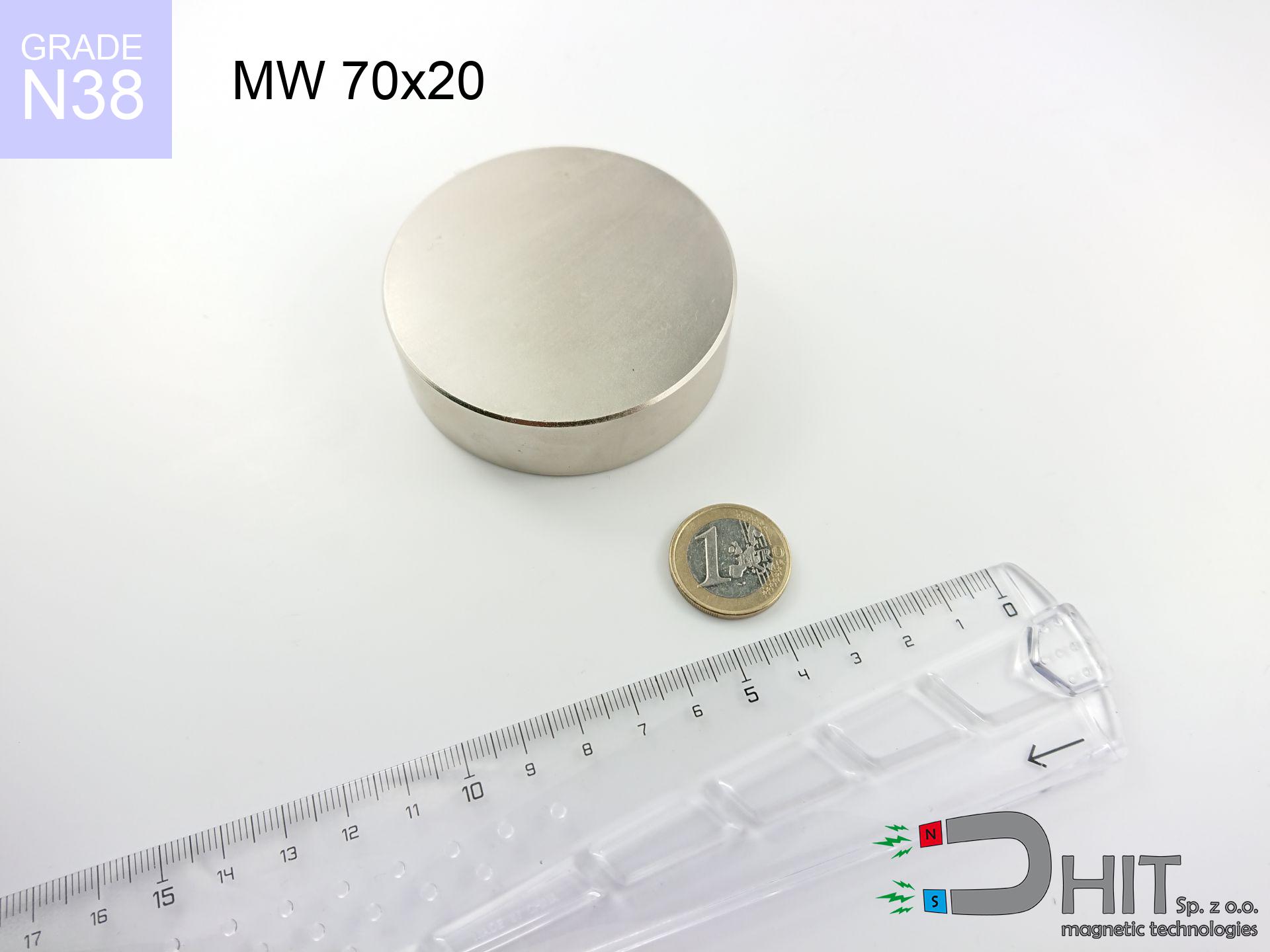
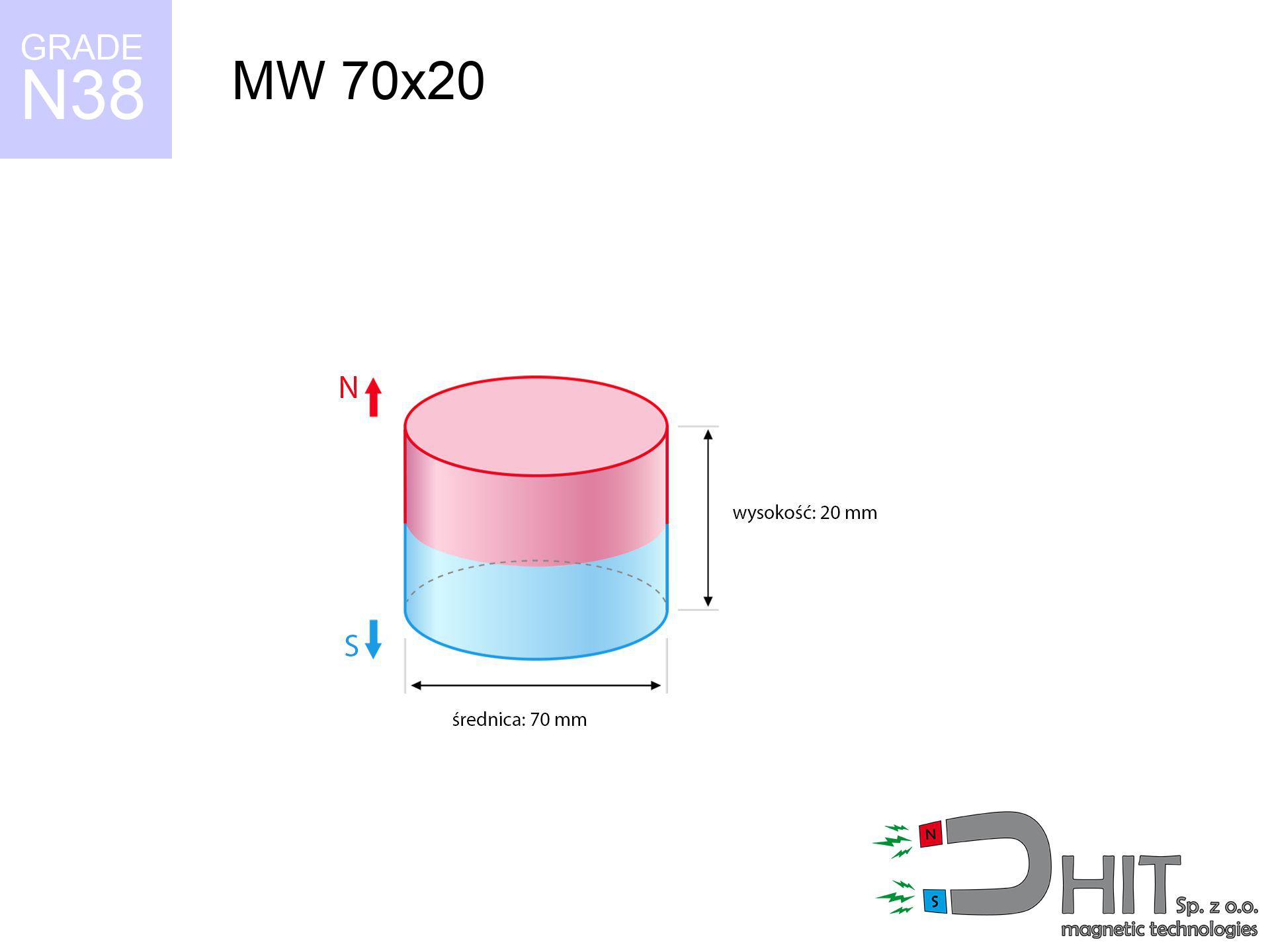
MW 70x20 / N38 - cylindrical magnet
cylindrical magnet
Catalog no 010095
GTIN/EAN: 5906301810940
Diameter Ø
70 mm [±0,1 mm]
Height
20 mm [±0,1 mm]
Weight
577.27 g
Magnetization Direction
↑ axial
Load capacity
99.83 kg / 979.00 N
Magnetic Induction
307.57 mT / 3076 Gs
Coating
[NiCuNi] Nickel
239.85 ZŁ with VAT / pcs + price for transport
195.00 ZŁ net + 23% VAT / pcs
bulk discounts:
Need more?Engineering report for this magnet
Full PDF analysis: pull and shear force, effect of distance, temperature and plate thickness, safety distances and the demagnetization curve.
Give us a call
+48 888 99 98 98
or drop us a message by means of
form
our website.
Strength along with shape of magnets can be analyzed using our
modular calculator.
Same-day shipping for orders placed before 14:00.
Technical details - MW 70x20 / N38 - cylindrical magnet
Specification / characteristics - MW 70x20 / N38 - cylindrical magnet
| properties | values |
|---|---|
| Cat. no. | 010095 |
| GTIN/EAN | 5906301810940 |
| Production/Distribution | Dhit sp. z o.o. |
| Country of origin | Poland / China / Germany |
| Customs code | 85059029 |
| Diameter Ø | 70 mm [±0,1 mm] |
| Height | 20 mm [±0,1 mm] |
| Weight | 577.27 g |
| Magnetization Direction | ↑ axial |
| Load capacity ~ ? | 99.83 kg / 979.00 N |
| Magnetic Induction ~ ? | 307.57 mT / 3076 Gs |
| Coating | [NiCuNi] Nickel |
| Manufacturing Tolerance | ±0.1 mm |
Magnetic properties of material N38
| properties | values | units |
|---|---|---|
| remenance Br [min. - max.] ? | 12.2-12.6 | kGs |
| remenance Br [min. - max.] ? | 1220-1260 | mT |
| coercivity bHc ? | 10.8-11.5 | kOe |
| coercivity bHc ? | 860-915 | kA/m |
| actual internal force iHc | ≥ 12 | kOe |
| actual internal force iHc | ≥ 955 | kA/m |
| energy density [min. - max.] ? | 36-38 | BH max MGOe |
| energy density [min. - max.] ? | 287-303 | BH max KJ/m |
| max. temperature ? | ≤ 80 | °C |
Physical properties of sintered neodymium magnets Nd2Fe14B at 20°C
| properties | values | units |
|---|---|---|
| Vickers hardness | ≥550 | Hv |
| Density | ≥7.4 | g/cm3 |
| Curie Temperature TC | 312 - 380 | °C |
| Curie Temperature TF | 593 - 716 | °F |
| Specific resistance | 150 | μΩ⋅cm |
| Bending strength | 250 | MPa |
| Compressive strength | 1000~1100 | MPa |
| Thermal expansion parallel (∥) to orientation (M) | (3-4) x 10-6 | °C-1 |
| Thermal expansion perpendicular (⊥) to orientation (M) | -(1-3) x 10-6 | °C-1 |
| Young's modulus | 1.7 x 10⁴ | kg/mm² |
Physical modeling of the product - report
These data constitute the outcome of a physical analysis. Values are based on models for the class Nd2Fe14B. Actual performance might slightly differ. Treat these data as a preliminary roadmap for designers.
Table 1: Static pull force (force vs gap) - power drop
MW 70x20 / N38
| Distance (mm) | Induction (Gauss) / mT | Pull Force (kg/lbs/g/N) | Risk Status |
|---|---|---|---|
| 0 mm |
3075 Gs
307.5 mT
|
99.83 kg / 220.09 pounds
99830.0 g / 979.3 N
|
critical level |
| 1 mm |
3013 Gs
301.3 mT
|
95.80 kg / 211.21 pounds
95804.4 g / 939.8 N
|
critical level |
| 2 mm |
2946 Gs
294.6 mT
|
91.59 kg / 201.92 pounds
91587.7 g / 898.5 N
|
critical level |
| 3 mm |
2875 Gs
287.5 mT
|
87.27 kg / 192.39 pounds
87266.0 g / 856.1 N
|
critical level |
| 5 mm |
2727 Gs
272.7 mT
|
78.48 kg / 173.02 pounds
78482.2 g / 769.9 N
|
critical level |
| 10 mm |
2332 Gs
233.2 mT
|
57.38 kg / 126.50 pounds
57380.6 g / 562.9 N
|
critical level |
| 15 mm |
1942 Gs
194.2 mT
|
39.80 kg / 87.73 pounds
39795.7 g / 390.4 N
|
critical level |
| 20 mm |
1590 Gs
159.0 mT
|
26.68 kg / 58.82 pounds
26680.3 g / 261.7 N
|
critical level |
| 30 mm |
1044 Gs
104.4 mT
|
11.51 kg / 25.38 pounds
11511.2 g / 112.9 N
|
critical level |
| 50 mm |
466 Gs
46.6 mT
|
2.29 kg / 5.06 pounds
2294.1 g / 22.5 N
|
medium risk |
Table 2: Slippage hold (vertical surface)
MW 70x20 / N38
| Distance (mm) | Friction coefficient | Pull Force (kg/lbs/g/N) |
|---|---|---|
| 0 mm | Stal (~0.2) |
19.97 kg / 44.02 pounds
19966.0 g / 195.9 N
|
| 1 mm | Stal (~0.2) |
19.16 kg / 42.24 pounds
19160.0 g / 188.0 N
|
| 2 mm | Stal (~0.2) |
18.32 kg / 40.38 pounds
18318.0 g / 179.7 N
|
| 3 mm | Stal (~0.2) |
17.45 kg / 38.48 pounds
17454.0 g / 171.2 N
|
| 5 mm | Stal (~0.2) |
15.70 kg / 34.60 pounds
15696.0 g / 154.0 N
|
| 10 mm | Stal (~0.2) |
11.48 kg / 25.30 pounds
11476.0 g / 112.6 N
|
| 15 mm | Stal (~0.2) |
7.96 kg / 17.55 pounds
7960.0 g / 78.1 N
|
| 20 mm | Stal (~0.2) |
5.34 kg / 11.76 pounds
5336.0 g / 52.3 N
|
| 30 mm | Stal (~0.2) |
2.30 kg / 5.08 pounds
2302.0 g / 22.6 N
|
| 50 mm | Stal (~0.2) |
0.46 kg / 1.01 pounds
458.0 g / 4.5 N
|
Table 3: Wall mounting (shearing) - vertical pull
MW 70x20 / N38
| Surface type | Friction coefficient / % Mocy | Max load (kg/lbs/g/N) |
|---|---|---|
| Raw steel |
µ = 0.3
30% Nominalnej Siły
|
29.95 kg / 66.03 pounds
29949.0 g / 293.8 N
|
| Painted steel (standard) |
µ = 0.2
20% Nominalnej Siły
|
19.97 kg / 44.02 pounds
19966.0 g / 195.9 N
|
| Oily/slippery steel |
µ = 0.1
10% Nominalnej Siły
|
9.98 kg / 22.01 pounds
9983.0 g / 97.9 N
|
| Magnet with anti-slip rubber |
µ = 0.5
50% Nominalnej Siły
|
49.92 kg / 110.04 pounds
49915.0 g / 489.7 N
|
Table 4: Steel thickness (substrate influence) - sheet metal selection
MW 70x20 / N38
| Steel thickness (mm) | % power | Real pull force (kg/lbs/g/N) |
|---|---|---|
| 0.5 mm |
|
3.33 kg / 7.34 pounds
3327.7 g / 32.6 N
|
| 1 mm |
|
8.32 kg / 18.34 pounds
8319.2 g / 81.6 N
|
| 2 mm |
|
16.64 kg / 36.68 pounds
16638.3 g / 163.2 N
|
| 3 mm |
|
24.96 kg / 55.02 pounds
24957.5 g / 244.8 N
|
| 5 mm |
|
41.60 kg / 91.70 pounds
41595.8 g / 408.1 N
|
| 10 mm |
|
83.19 kg / 183.41 pounds
83191.7 g / 816.1 N
|
| 11 mm |
|
91.51 kg / 201.75 pounds
91510.8 g / 897.7 N
|
| 12 mm |
|
99.83 kg / 220.09 pounds
99830.0 g / 979.3 N
|
Table 5: Thermal resistance (stability) - power drop
MW 70x20 / N38
| Ambient temp. (°C) | Power loss | Remaining pull (kg/lbs/g/N) | Status |
|---|---|---|---|
| 20 °C | 0.0% |
99.83 kg / 220.09 pounds
99830.0 g / 979.3 N
|
OK |
| 40 °C | -2.2% |
97.63 kg / 215.25 pounds
97633.7 g / 957.8 N
|
OK |
| 60 °C | -4.4% |
95.44 kg / 210.40 pounds
95437.5 g / 936.2 N
|
|
| 80 °C | -6.6% |
93.24 kg / 205.56 pounds
93241.2 g / 914.7 N
|
|
| 100 °C | -28.8% |
71.08 kg / 156.70 pounds
71079.0 g / 697.3 N
|
Table 6: Magnet-Magnet interaction (repulsion) - field range
MW 70x20 / N38
| Gap (mm) | Attraction (kg/lbs) (N-S) | Lateral Force (kg/lbs/g/N) | Repulsion (kg/lbs) (N-N) |
|---|---|---|---|
| 0 mm |
224.41 kg / 494.73 pounds
4 665 Gs
|
33.66 kg / 74.21 pounds
33661 g / 330.2 N
|
N/A |
| 1 mm |
219.98 kg / 484.97 pounds
6 090 Gs
|
33.00 kg / 72.74 pounds
32997 g / 323.7 N
|
197.98 kg / 436.47 pounds
~0 Gs
|
| 2 mm |
215.36 kg / 474.78 pounds
6 026 Gs
|
32.30 kg / 71.22 pounds
32304 g / 316.9 N
|
193.82 kg / 427.31 pounds
~0 Gs
|
| 3 mm |
210.66 kg / 464.41 pounds
5 959 Gs
|
31.60 kg / 69.66 pounds
31598 g / 310.0 N
|
189.59 kg / 417.97 pounds
~0 Gs
|
| 5 mm |
201.05 kg / 443.23 pounds
5 822 Gs
|
30.16 kg / 66.48 pounds
30157 g / 295.8 N
|
180.94 kg / 398.91 pounds
~0 Gs
|
| 10 mm |
176.42 kg / 388.94 pounds
5 454 Gs
|
26.46 kg / 58.34 pounds
26463 g / 259.6 N
|
158.78 kg / 350.05 pounds
~0 Gs
|
| 20 mm |
128.99 kg / 284.36 pounds
4 663 Gs
|
19.35 kg / 42.65 pounds
19348 g / 189.8 N
|
116.09 kg / 255.93 pounds
~0 Gs
|
| 50 mm |
39.50 kg / 87.08 pounds
2 581 Gs
|
5.93 kg / 13.06 pounds
5925 g / 58.1 N
|
35.55 kg / 78.38 pounds
~0 Gs
|
| 60 mm |
25.88 kg / 57.05 pounds
2 089 Gs
|
3.88 kg / 8.56 pounds
3881 g / 38.1 N
|
23.29 kg / 51.34 pounds
~0 Gs
|
| 70 mm |
17.01 kg / 37.49 pounds
1 693 Gs
|
2.55 kg / 5.62 pounds
2551 g / 25.0 N
|
15.31 kg / 33.74 pounds
~0 Gs
|
| 80 mm |
11.28 kg / 24.86 pounds
1 379 Gs
|
1.69 kg / 3.73 pounds
1692 g / 16.6 N
|
10.15 kg / 22.38 pounds
~0 Gs
|
| 90 mm |
7.57 kg / 16.69 pounds
1 130 Gs
|
1.14 kg / 2.50 pounds
1136 g / 11.1 N
|
6.81 kg / 15.02 pounds
~0 Gs
|
| 100 mm |
5.16 kg / 11.37 pounds
932 Gs
|
0.77 kg / 1.71 pounds
774 g / 7.6 N
|
4.64 kg / 10.23 pounds
~0 Gs
|
Table 7: Hazards (electronics) - warnings
MW 70x20 / N38
| Object / Device | Limit (Gauss) / mT | Safe distance |
|---|---|---|
| Pacemaker | 5 Gs (0.5 mT) | 30.5 cm |
| Hearing aid | 10 Gs (1.0 mT) | 24.0 cm |
| Mechanical watch | 20 Gs (2.0 mT) | 18.5 cm |
| Mobile device | 40 Gs (4.0 mT) | 14.5 cm |
| Remote | 50 Gs (5.0 mT) | 13.5 cm |
| Payment card | 400 Gs (40.0 mT) | 5.5 cm |
| HDD hard drive | 600 Gs (60.0 mT) | 4.5 cm |
Table 8: Dynamics (kinetic energy) - warning
MW 70x20 / N38
| Start from (mm) | Speed (km/h) | Energy (J) | Predicted outcome |
|---|---|---|---|
| 10 mm |
17.39 km/h
(4.83 m/s)
|
6.73 J | |
| 30 mm |
24.57 km/h
(6.83 m/s)
|
13.45 J | |
| 50 mm |
30.08 km/h
(8.36 m/s)
|
20.15 J | |
| 100 mm |
41.97 km/h
(11.66 m/s)
|
39.23 J |
Table 9: Anti-corrosion coating durability
MW 70x20 / N38
| Technical parameter | Value / Description |
|---|---|
| Coating type | [NiCuNi] Nickel |
| Layer structure | Nickel - Copper - Nickel |
| Layer thickness | 10-20 µm |
| Salt spray test (SST) ? | 24 h |
| Recommended environment | Indoors only (dry) |
Table 10: Electrical data (Pc)
MW 70x20 / N38
| Parameter | Value | SI Unit / Description |
|---|---|---|
| Magnetic Flux | 128 363 Mx | 1283.6 µWb |
| Pc Coefficient | 0.39 | Low (Flat) |
Table 11: Underwater work (magnet fishing)
MW 70x20 / N38
| Environment | Effective steel pull | Effect |
|---|---|---|
| Air (land) | 99.83 kg | Standard |
| Water (riverbed) |
114.31 kg
(+14.48 kg buoyancy gain)
|
+14.5% |
1. Shear force
*Caution: On a vertical surface, the magnet holds merely a fraction of its nominal pull.
2. Efficiency vs thickness
*Thin metal sheet (e.g. computer case) drastically limits the holding force.
3. Temperature resistance
*For N38 material, the critical limit is 80°C.
4. Demagnetization curve and operating point (B-H)
chart generated for the permeance coefficient Pc (Permeance Coefficient) = 0.39
This simulation demonstrates the magnetic stability of the selected magnet under specific geometric conditions. The solid red line represents the demagnetization curve (material potential), while the dashed blue line is the load line based on the magnet's geometry. The Pc (Permeance Coefficient), also known as the load line slope, is a dimensionless value that describes the relationship between the magnet's shape and its magnetic stability. The intersection of these two lines (the black dot) is the operating point — it determines the actual magnetic flux density generated by the magnet in this specific configuration. A higher Pc value means the magnet is more 'slender' (tall relative to its area), resulting in a higher operating point and better resistance to irreversible demagnetization caused by external fields or temperature. A value of 0.42 is relatively low (typical for flat magnets), meaning the operating point is closer to the 'knee' of the curve — caution is advised when operating at temperatures near the maximum limit to avoid strength loss.
Chemical composition
| iron (Fe) | 64% – 68% |
| neodymium (Nd) | 29% – 32% |
| boron (B) | 1.1% – 1.2% |
| dysprosium (Dy) | 0.5% – 2.0% |
| coating (Ni-Cu-Ni) | < 0.05% |
Environmental data
| recyclability (EoL) | 100% |
| recycled raw materials | ~10% (pre-cons) |
| carbon footprint | low / zredukowany |
| waste code (EWC) | 16 02 16 |
See also products
![BM 750x180x70 [4x M8] - magnetic beam](https://cdn3.dhit.pl/graphics/products/bm-750x180x70-4x-m8-zif.jpg "BM 750x180x70 [4x M8] - magnetic beam")
![SM 32x400 [2xM8] / N52 - magnetic separator](https://cdn3.dhit.pl/graphics/products/sm-32x400-2xm8-led.jpg "SM 32x400 [2xM8] / N52 - magnetic separator")


Advantages and disadvantages of rare earth magnets.
Pros
- They do not lose power, even over around 10 years – the decrease in strength is only ~1% (based on measurements),
- Neodymium magnets prove to be remarkably resistant to magnetic field loss caused by magnetic disturbances,
- The use of an metallic finish of noble metals (nickel, gold, silver) causes the element to have aesthetics,
- Magnets are characterized by extremely high magnetic induction on the outer layer,
- Neodymium magnets are characterized by extremely high magnetic induction on the magnet surface and are able to act (depending on the shape) even at a temperature of 230°C or more...
- Thanks to versatility in designing and the ability to customize to unusual requirements,
- Universal use in electronics industry – they are used in computer drives, electric drive systems, precision medical tools, and technologically advanced constructions.
- Thanks to their power density, small magnets offer high operating force, occupying minimum space,
Cons
- They are fragile upon too strong impacts. To avoid cracks, it is worth securing magnets in special housings. Such protection not only shields the magnet but also increases its resistance to damage
- NdFeB magnets demagnetize when exposed to high temperatures. After reaching 80°C, many of them experience permanent drop of strength (a factor is the shape as well as dimensions of the magnet). We offer magnets specially adapted to work at temperatures up to 230°C marked [AH], which are extremely resistant to heat
- Due to the susceptibility of magnets to corrosion in a humid environment, we recommend using waterproof magnets made of rubber, plastic or other material stable to moisture, when using outdoors
- Due to limitations in producing threads and complicated forms in magnets, we recommend using a housing - magnetic mechanism.
- Health risk resulting from small fragments of magnets pose a threat, in case of ingestion, which gains importance in the context of child safety. Furthermore, small elements of these products can be problematic in diagnostics medical when they are in the body.
- With mass production the cost of neodymium magnets can be a barrier,
Holding force characteristics
Best holding force of the magnet in ideal parameters – what contributes to it?
- with the use of a sheet made of low-carbon steel, guaranteeing maximum field concentration
- with a thickness no less than 10 mm
- with an ground contact surface
- without the slightest insulating layer between the magnet and steel
- during detachment in a direction vertical to the plane
- in temp. approx. 20°C
What influences lifting capacity in practice
- Space between magnet and steel – every millimeter of distance (caused e.g. by varnish or dirt) significantly weakens the magnet efficiency, often by half at just 0.5 mm.
- Pull-off angle – remember that the magnet holds strongest perpendicularly. Under sliding down, the capacity drops significantly, often to levels of 20-30% of the maximum value.
- Steel thickness – insufficiently thick sheet does not accept the full field, causing part of the flux to be lost to the other side.
- Plate material – low-carbon steel attracts best. Alloy admixtures reduce magnetic permeability and lifting capacity.
- Surface condition – ground elements ensure maximum contact, which improves force. Uneven metal weaken the grip.
- Thermal conditions – neodymium magnets have a sensitivity to temperature. At higher temperatures they are weaker, and at low temperatures they can be stronger (up to a certain limit).
Lifting capacity testing was performed on plates with a smooth surface of optimal thickness, under a perpendicular pulling force, however under attempts to slide the magnet the load capacity is reduced by as much as fivefold. Moreover, even a small distance between the magnet and the plate lowers the holding force.
Safety rules for work with NdFeB magnets
Allergic reactions
Studies show that nickel (the usual finish) is a potent allergen. For allergy sufferers, refrain from touching magnets with bare hands or choose coated magnets.
Warning for heart patients
For implant holders: Strong magnetic fields disrupt medical devices. Maintain minimum 30 cm distance or ask another person to work with the magnets.
Bodily injuries
Big blocks can crush fingers in a fraction of a second. Under no circumstances place your hand betwixt two attracting surfaces.
Keep away from children
Only for adults. Small elements pose a choking risk, leading to severe trauma. Store away from kids and pets.
Permanent damage
Keep cool. Neodymium magnets are sensitive to heat. If you need resistance above 80°C, look for HT versions (H, SH, UH).
Fire warning
Powder produced during cutting of magnets is self-igniting. Avoid drilling into magnets unless you are an expert.
Keep away from computers
Do not bring magnets close to a wallet, laptop, or screen. The magnetism can irreversibly ruin these devices and erase data from cards.
Precision electronics
Remember: neodymium magnets produce a field that confuses precision electronics. Maintain a safe distance from your mobile, device, and navigation systems.
Powerful field
Handle magnets consciously. Their powerful strength can shock even professionals. Stay alert and do not underestimate their power.
Material brittleness
Watch out for shards. Magnets can fracture upon violent connection, launching sharp fragments into the air. We recommend safety glasses.
Tabela kosztu i czasu dostawy
Płatność przed wysyłką:

GLS kurier
Przesyłka będzie u Ciebie za 2-3 dni
14.99 ZŁ

InPost Paczkomaty 24/7
Przesyłka będzie u Ciebie za 1-2 dni
12.30 ZŁ
Płatność przy odbiorze (pobranie):
GLS kurier
Przesyłka będzie u Ciebie za 1-2 dni
23.00 ZŁ
Rate the product
Your rating