
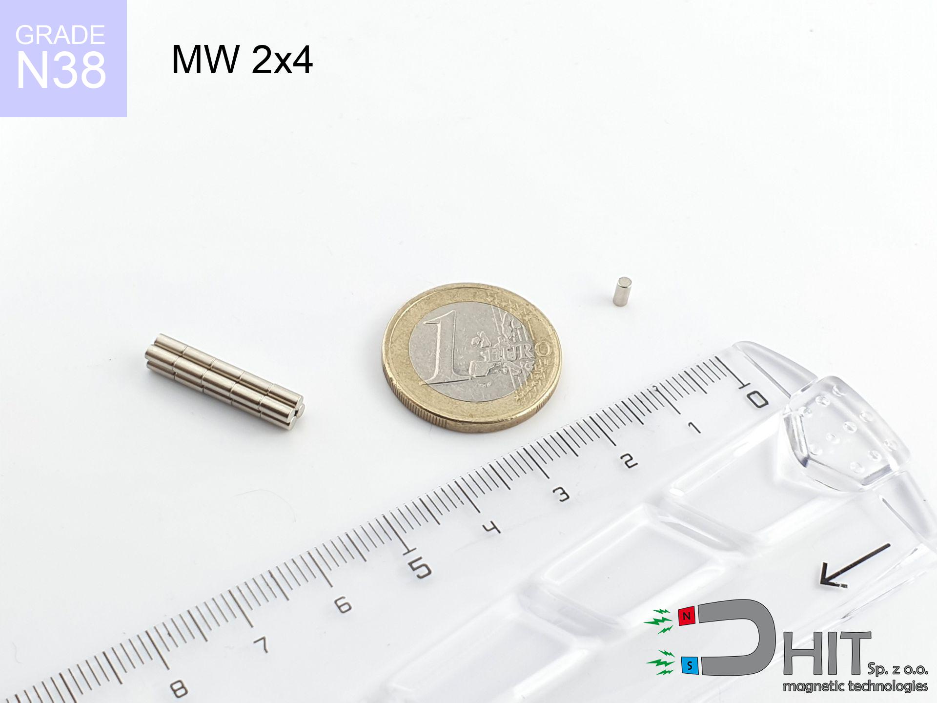

MW 2x4 / N38 - cylindrical magnet
cylindrical magnet
Catalog no 010055
GTIN/EAN: 5906301810544
Diameter Ø
2 mm [±0,1 mm]
Height
4 mm [±0,1 mm]
Weight
0.09 g
Magnetization Direction
↑ axial
Load capacity
0.09 kg / 0.86 N
Magnetic Induction
597.70 mT / 5977 Gs
Coating
[NiCuNi] Nickel
0.209 ZŁ with VAT / pcs + price for transport
0.1700 ZŁ net + 23% VAT / pcs
bulk discounts:
Need more?
Pick up the phone and ask
+48 22 499 98 98
or contact us using
our online form
the contact form page.
Strength as well as shape of neodymium magnets can be calculated with our
magnetic calculator.
Same-day shipping for orders placed before 14:00.
Technical parameters - MW 2x4 / N38 - cylindrical magnet
Specification / characteristics - MW 2x4 / N38 - cylindrical magnet
| properties | values |
|---|---|
| Cat. no. | 010055 |
| GTIN/EAN | 5906301810544 |
| Production/Distribution | Dhit sp. z o.o. |
| Country of origin | Poland / China / Germany |
| Customs code | 85059029 |
| Diameter Ø | 2 mm [±0,1 mm] |
| Height | 4 mm [±0,1 mm] |
| Weight | 0.09 g |
| Magnetization Direction | ↑ axial |
| Load capacity ~ ? | 0.09 kg / 0.86 N |
| Magnetic Induction ~ ? | 597.70 mT / 5977 Gs |
| Coating | [NiCuNi] Nickel |
| Manufacturing Tolerance | ±0.1 mm |
Magnetic properties of material N38
| properties | values | units |
|---|---|---|
| remenance Br [min. - max.] ? | 12.2-12.6 | kGs |
| remenance Br [min. - max.] ? | 1220-1260 | mT |
| coercivity bHc ? | 10.8-11.5 | kOe |
| coercivity bHc ? | 860-915 | kA/m |
| actual internal force iHc | ≥ 12 | kOe |
| actual internal force iHc | ≥ 955 | kA/m |
| energy density [min. - max.] ? | 36-38 | BH max MGOe |
| energy density [min. - max.] ? | 287-303 | BH max KJ/m |
| max. temperature ? | ≤ 80 | °C |
Physical properties of sintered neodymium magnets Nd2Fe14B at 20°C
| properties | values | units |
|---|---|---|
| Vickers hardness | ≥550 | Hv |
| Density | ≥7.4 | g/cm3 |
| Curie Temperature TC | 312 - 380 | °C |
| Curie Temperature TF | 593 - 716 | °F |
| Specific resistance | 150 | μΩ⋅cm |
| Bending strength | 250 | MPa |
| Compressive strength | 1000~1100 | MPa |
| Thermal expansion parallel (∥) to orientation (M) | (3-4) x 10-6 | °C-1 |
| Thermal expansion perpendicular (⊥) to orientation (M) | -(1-3) x 10-6 | °C-1 |
| Young's modulus | 1.7 x 10⁴ | kg/mm² |
Physical simulation of the product - report
The following values constitute the result of a engineering simulation. Results rely on algorithms for the class Nd2Fe14B. Real-world conditions may deviate from the simulation results. Please consider these data as a reference point when designing systems.
Table 1: Static force (pull vs gap) - characteristics
MW 2x4 / N38
| Distance (mm) | Induction (Gauss) / mT | Pull Force (kg/lbs/g/N) | Risk Status |
|---|---|---|---|
| 0 mm |
5954 Gs
595.4 mT
|
0.09 kg / 0.20 LBS
90.0 g / 0.9 N
|
low risk |
| 1 mm |
1696 Gs
169.6 mT
|
0.01 kg / 0.02 LBS
7.3 g / 0.1 N
|
low risk |
| 2 mm |
570 Gs
57.0 mT
|
0.00 kg / 0.00 LBS
0.8 g / 0.0 N
|
low risk |
| 3 mm |
256 Gs
25.6 mT
|
0.00 kg / 0.00 LBS
0.2 g / 0.0 N
|
low risk |
| 5 mm |
82 Gs
8.2 mT
|
0.00 kg / 0.00 LBS
0.0 g / 0.0 N
|
low risk |
| 10 mm |
15 Gs
1.5 mT
|
0.00 kg / 0.00 LBS
0.0 g / 0.0 N
|
low risk |
| 15 mm |
5 Gs
0.5 mT
|
0.00 kg / 0.00 LBS
0.0 g / 0.0 N
|
low risk |
| 20 mm |
2 Gs
0.2 mT
|
0.00 kg / 0.00 LBS
0.0 g / 0.0 N
|
low risk |
| 30 mm |
1 Gs
0.1 mT
|
0.00 kg / 0.00 LBS
0.0 g / 0.0 N
|
low risk |
| 50 mm |
0 Gs
0.0 mT
|
0.00 kg / 0.00 LBS
0.0 g / 0.0 N
|
low risk |
Table 2: Vertical force (wall)
MW 2x4 / N38
| Distance (mm) | Friction coefficient | Pull Force (kg/lbs/g/N) |
|---|---|---|
| 0 mm | Stal (~0.2) |
0.02 kg / 0.04 LBS
18.0 g / 0.2 N
|
| 1 mm | Stal (~0.2) |
0.00 kg / 0.00 LBS
2.0 g / 0.0 N
|
| 2 mm | Stal (~0.2) |
0.00 kg / 0.00 LBS
0.0 g / 0.0 N
|
| 3 mm | Stal (~0.2) |
0.00 kg / 0.00 LBS
0.0 g / 0.0 N
|
| 5 mm | Stal (~0.2) |
0.00 kg / 0.00 LBS
0.0 g / 0.0 N
|
| 10 mm | Stal (~0.2) |
0.00 kg / 0.00 LBS
0.0 g / 0.0 N
|
| 15 mm | Stal (~0.2) |
0.00 kg / 0.00 LBS
0.0 g / 0.0 N
|
| 20 mm | Stal (~0.2) |
0.00 kg / 0.00 LBS
0.0 g / 0.0 N
|
| 30 mm | Stal (~0.2) |
0.00 kg / 0.00 LBS
0.0 g / 0.0 N
|
| 50 mm | Stal (~0.2) |
0.00 kg / 0.00 LBS
0.0 g / 0.0 N
|
Table 3: Vertical assembly (shearing) - vertical pull
MW 2x4 / N38
| Surface type | Friction coefficient / % Mocy | Max load (kg/lbs/g/N) |
|---|---|---|
| Raw steel |
µ = 0.3
30% Nominalnej Siły
|
0.03 kg / 0.06 LBS
27.0 g / 0.3 N
|
| Painted steel (standard) |
µ = 0.2
20% Nominalnej Siły
|
0.02 kg / 0.04 LBS
18.0 g / 0.2 N
|
| Oily/slippery steel |
µ = 0.1
10% Nominalnej Siły
|
0.01 kg / 0.02 LBS
9.0 g / 0.1 N
|
| Magnet with anti-slip rubber |
µ = 0.5
50% Nominalnej Siły
|
0.05 kg / 0.10 LBS
45.0 g / 0.4 N
|
Table 4: Steel thickness (substrate influence) - power losses
MW 2x4 / N38
| Steel thickness (mm) | % power | Real pull force (kg/lbs/g/N) |
|---|---|---|
| 0.5 mm |
|
0.01 kg / 0.02 LBS
9.0 g / 0.1 N
|
| 1 mm |
|
0.02 kg / 0.05 LBS
22.5 g / 0.2 N
|
| 2 mm |
|
0.05 kg / 0.10 LBS
45.0 g / 0.4 N
|
| 3 mm |
|
0.07 kg / 0.15 LBS
67.5 g / 0.7 N
|
| 5 mm |
|
0.09 kg / 0.20 LBS
90.0 g / 0.9 N
|
| 10 mm |
|
0.09 kg / 0.20 LBS
90.0 g / 0.9 N
|
| 11 mm |
|
0.09 kg / 0.20 LBS
90.0 g / 0.9 N
|
| 12 mm |
|
0.09 kg / 0.20 LBS
90.0 g / 0.9 N
|
Table 5: Thermal stability (material behavior) - thermal limit
MW 2x4 / N38
| Ambient temp. (°C) | Power loss | Remaining pull (kg/lbs/g/N) | Status |
|---|---|---|---|
| 20 °C | 0.0% |
0.09 kg / 0.20 LBS
90.0 g / 0.9 N
|
OK |
| 40 °C | -2.2% |
0.09 kg / 0.19 LBS
88.0 g / 0.9 N
|
OK |
| 60 °C | -4.4% |
0.09 kg / 0.19 LBS
86.0 g / 0.8 N
|
OK |
| 80 °C | -6.6% |
0.08 kg / 0.19 LBS
84.1 g / 0.8 N
|
|
| 100 °C | -28.8% |
0.06 kg / 0.14 LBS
64.1 g / 0.6 N
|
Table 6: Magnet-Magnet interaction (repulsion) - forces in the system
MW 2x4 / N38
| Gap (mm) | Attraction (kg/lbs) (N-S) | Sliding Force (kg/lbs/g/N) | Repulsion (kg/lbs) (N-N) |
|---|---|---|---|
| 0 mm |
0.69 kg / 1.51 LBS
6 090 Gs
|
0.10 kg / 0.23 LBS
103 g / 1.0 N
|
N/A |
| 1 mm |
0.21 kg / 0.46 LBS
6 559 Gs
|
0.03 kg / 0.07 LBS
31 g / 0.3 N
|
0.19 kg / 0.41 LBS
~0 Gs
|
| 2 mm |
0.06 kg / 0.12 LBS
3 391 Gs
|
0.01 kg / 0.02 LBS
8 g / 0.1 N
|
0.05 kg / 0.11 LBS
~0 Gs
|
| 3 mm |
0.02 kg / 0.04 LBS
1 883 Gs
|
0.00 kg / 0.01 LBS
3 g / 0.0 N
|
0.02 kg / 0.03 LBS
~0 Gs
|
| 5 mm |
0.00 kg / 0.01 LBS
743 Gs
|
0.00 kg / 0.00 LBS
0 g / 0.0 N
|
0.00 kg / 0.00 LBS
~0 Gs
|
| 10 mm |
0.00 kg / 0.00 LBS
165 Gs
|
0.00 kg / 0.00 LBS
0 g / 0.0 N
|
0.00 kg / 0.00 LBS
~0 Gs
|
| 20 mm |
0.00 kg / 0.00 LBS
30 Gs
|
0.00 kg / 0.00 LBS
0 g / 0.0 N
|
0.00 kg / 0.00 LBS
~0 Gs
|
| 50 mm |
0.00 kg / 0.00 LBS
3 Gs
|
0.00 kg / 0.00 LBS
0 g / 0.0 N
|
0.00 kg / 0.00 LBS
~0 Gs
|
| 60 mm |
0.00 kg / 0.00 LBS
2 Gs
|
0.00 kg / 0.00 LBS
0 g / 0.0 N
|
0.00 kg / 0.00 LBS
~0 Gs
|
| 70 mm |
0.00 kg / 0.00 LBS
1 Gs
|
0.00 kg / 0.00 LBS
0 g / 0.0 N
|
0.00 kg / 0.00 LBS
~0 Gs
|
| 80 mm |
0.00 kg / 0.00 LBS
1 Gs
|
0.00 kg / 0.00 LBS
0 g / 0.0 N
|
0.00 kg / 0.00 LBS
~0 Gs
|
| 90 mm |
0.00 kg / 0.00 LBS
0 Gs
|
0.00 kg / 0.00 LBS
0 g / 0.0 N
|
0.00 kg / 0.00 LBS
~0 Gs
|
| 100 mm |
0.00 kg / 0.00 LBS
0 Gs
|
0.00 kg / 0.00 LBS
0 g / 0.0 N
|
0.00 kg / 0.00 LBS
~0 Gs
|
Table 7: Protective zones (implants) - precautionary measures
MW 2x4 / N38
| Object / Device | Limit (Gauss) / mT | Safe distance |
|---|---|---|
| Pacemaker | 5 Gs (0.5 mT) | 2.0 cm |
| Hearing aid | 10 Gs (1.0 mT) | 1.5 cm |
| Mechanical watch | 20 Gs (2.0 mT) | 1.0 cm |
| Phone / Smartphone | 40 Gs (4.0 mT) | 1.0 cm |
| Remote | 50 Gs (5.0 mT) | 1.0 cm |
| Payment card | 400 Gs (40.0 mT) | 0.5 cm |
| HDD hard drive | 600 Gs (60.0 mT) | 0.5 cm |
Table 8: Dynamics (cracking risk) - warning
MW 2x4 / N38
| Start from (mm) | Speed (km/h) | Energy (J) | Predicted outcome |
|---|---|---|---|
| 10 mm |
31.89 km/h
(8.86 m/s)
|
0.00 J | |
| 30 mm |
55.24 km/h
(15.34 m/s)
|
0.01 J | |
| 50 mm |
71.31 km/h
(19.81 m/s)
|
0.02 J | |
| 100 mm |
100.85 km/h
(28.01 m/s)
|
0.04 J |
Table 9: Anti-corrosion coating durability
MW 2x4 / N38
| Technical parameter | Value / Description |
|---|---|
| Coating type | [NiCuNi] Nickel |
| Layer structure | Nickel - Copper - Nickel |
| Layer thickness | 10-20 µm |
| Salt spray test (SST) ? | 24 h |
| Recommended environment | Indoors only (dry) |
Table 10: Construction data (Flux)
MW 2x4 / N38
| Parameter | Value | SI Unit / Description |
|---|---|---|
| Magnetic Flux | 209 Mx | 2.1 µWb |
| Pc Coefficient | 1.21 | High (Stable) |
Table 11: Physics of underwater searching
MW 2x4 / N38
| Environment | Effective steel pull | Effect |
|---|---|---|
| Air (land) | 0.09 kg | Standard |
| Water (riverbed) |
0.10 kg
(+0.01 kg buoyancy gain)
|
+14.5% |
1. Wall mount (shear)
*Caution: On a vertical surface, the magnet retains just ~20% of its perpendicular strength.
2. Steel thickness impact
*Thin metal sheet (e.g. computer case) severely limits the holding force.
3. Thermal stability
*For N38 material, the max working temp is 80°C.
4. Demagnetization curve and operating point (B-H)
chart generated for the permeance coefficient Pc (Permeance Coefficient) = 1.21
The chart above illustrates the magnetic characteristics of the material within the second quadrant of the hysteresis loop. The solid red line represents the demagnetization curve (material potential), while the dashed blue line is the load line based on the magnet's geometry. The Pc (Permeance Coefficient), also known as the load line slope, is a dimensionless value that describes the relationship between the magnet's shape and its magnetic stability. The intersection of these two lines (the black dot) is the operating point — it determines the actual magnetic flux density generated by the magnet in this specific configuration. A higher Pc value means the magnet is more 'slender' (tall relative to its area), resulting in a higher operating point and better resistance to irreversible demagnetization caused by external fields or temperature. A value of 0.42 is relatively low (typical for flat magnets), meaning the operating point is closer to the 'knee' of the curve — caution is advised when operating at temperatures near the maximum limit to avoid strength loss.
Material specification
| iron (Fe) | 64% – 68% |
| neodymium (Nd) | 29% – 32% |
| boron (B) | 1.1% – 1.2% |
| dysprosium (Dy) | 0.5% – 2.0% |
| coating (Ni-Cu-Ni) | < 0.05% |
Ecology and recycling (GPSR)
| recyclability (EoL) | 100% |
| recycled raw materials | ~10% (pre-cons) |
| carbon footprint | low / zredukowany |
| waste code (EWC) | 16 02 16 |
Check out also proposals


![SM 32x250 [2xM8] / N52 - magnetic separator](https://cdn3.dhit.pl/graphics/products/sm-32x250-2xm8-guf.jpg "SM 32x250 [2xM8] / N52 - magnetic separator")

Pros as well as cons of rare earth magnets.
Strengths
- They virtually do not lose strength, because even after 10 years the decline in efficiency is only ~1% (according to literature),
- Neodymium magnets are distinguished by exceptionally resistant to magnetic field loss caused by external field sources,
- Thanks to the smooth finish, the plating of nickel, gold, or silver-plated gives an professional appearance,
- The surface of neodymium magnets generates a unique magnetic field – this is a distinguishing feature,
- Made from properly selected components, these magnets show impressive resistance to high heat, enabling them to function (depending on their form) at temperatures up to 230°C and above...
- Considering the possibility of free forming and customization to custom projects, neodymium magnets can be manufactured in a wide range of forms and dimensions, which expands the range of possible applications,
- Huge importance in innovative solutions – they find application in data components, motor assemblies, precision medical tools, also technologically advanced constructions.
- Relatively small size with high pulling force – neodymium magnets offer high power in compact dimensions, which allows their use in small systems
Limitations
- They are fragile upon heavy impacts. To avoid cracks, it is worth securing magnets using a steel holder. Such protection not only shields the magnet but also improves its resistance to damage
- When exposed to high temperature, neodymium magnets experience a drop in strength. Often, when the temperature exceeds 80°C, their strength decreases (depending on the size, as well as shape of the magnet). For those who need magnets for extreme conditions, we offer [AH] versions withstanding up to 230°C
- Magnets exposed to a humid environment can rust. Therefore during using outdoors, we recommend using water-impermeable magnets made of rubber, plastic or other material protecting against moisture
- We recommend cover - magnetic holder, due to difficulties in producing nuts inside the magnet and complex shapes.
- Health risk to health – tiny shards of magnets pose a threat, when accidentally swallowed, which is particularly important in the context of child health protection. It is also worth noting that small components of these magnets can be problematic in diagnostics medical after entering the body.
- High unit price – neodymium magnets have a higher price than other types of magnets (e.g. ferrite), which hinders application in large quantities
Pull force analysis
Maximum magnetic pulling force – what contributes to it?
- on a base made of structural steel, optimally conducting the magnetic field
- whose thickness reaches at least 10 mm
- characterized by even structure
- with direct contact (no coatings)
- during detachment in a direction perpendicular to the mounting surface
- in neutral thermal conditions
Lifting capacity in practice – influencing factors
- Distance – the presence of any layer (rust, tape, gap) acts as an insulator, which lowers capacity steeply (even by 50% at 0.5 mm).
- Force direction – note that the magnet holds strongest perpendicularly. Under shear forces, the holding force drops drastically, often to levels of 20-30% of the maximum value.
- Metal thickness – the thinner the sheet, the weaker the hold. Magnetic flux penetrates through instead of converting into lifting capacity.
- Steel grade – ideal substrate is pure iron steel. Stainless steels may have worse magnetic properties.
- Base smoothness – the smoother and more polished the surface, the better the adhesion and stronger the hold. Unevenness creates an air distance.
- Temperature – heating the magnet causes a temporary drop of force. Check the maximum operating temperature for a given model.
Holding force was checked on a smooth steel plate of 20 mm thickness, when a perpendicular force was applied, however under attempts to slide the magnet the holding force is lower. Additionally, even a minimal clearance between the magnet and the plate decreases the holding force.
H&S for magnets
Do not underestimate power
Use magnets consciously. Their huge power can surprise even professionals. Be vigilant and do not underestimate their force.
Medical implants
Individuals with a pacemaker should maintain an large gap from magnets. The magnetic field can interfere with the operation of the implant.
Bodily injuries
Protect your hands. Two powerful magnets will join instantly with a force of several hundred kilograms, destroying everything in their path. Be careful!
Maximum temperature
Watch the temperature. Heating the magnet above 80 degrees Celsius will permanently weaken its properties and pulling force.
Impact on smartphones
GPS units and mobile phones are highly susceptible to magnetism. Close proximity with a strong magnet can decalibrate the internal compass in your phone.
Flammability
Machining of NdFeB material carries a risk of fire risk. Neodymium dust oxidizes rapidly with oxygen and is hard to extinguish.
Nickel allergy
Studies show that the nickel plating (standard magnet coating) is a common allergen. If you have an allergy, refrain from touching magnets with bare hands and select encased magnets.
Fragile material
Despite metallic appearance, neodymium is brittle and not impact-resistant. Avoid impacts, as the magnet may shatter into hazardous fragments.
Choking Hazard
Always keep magnets out of reach of children. Risk of swallowing is significant, and the effects of magnets clamping inside the body are life-threatening.
Magnetic media
Intense magnetic fields can destroy records on payment cards, HDDs, and storage devices. Stay away of min. 10 cm.
Tabela kosztu i czasu dostawy
Płatność przed wysyłką:

GLS kurier
Przesyłka będzie u Ciebie za 2-3 dni
14.99 ZŁ

InPost Paczkomaty 24/7
Przesyłka będzie u Ciebie za 1-2 dni
12.30 ZŁ
Płatność przy odbiorze (pobranie):
GLS kurier
Przesyłka będzie u Ciebie za 1-2 dni
23.00 ZŁ
Rate the product
Your rating