
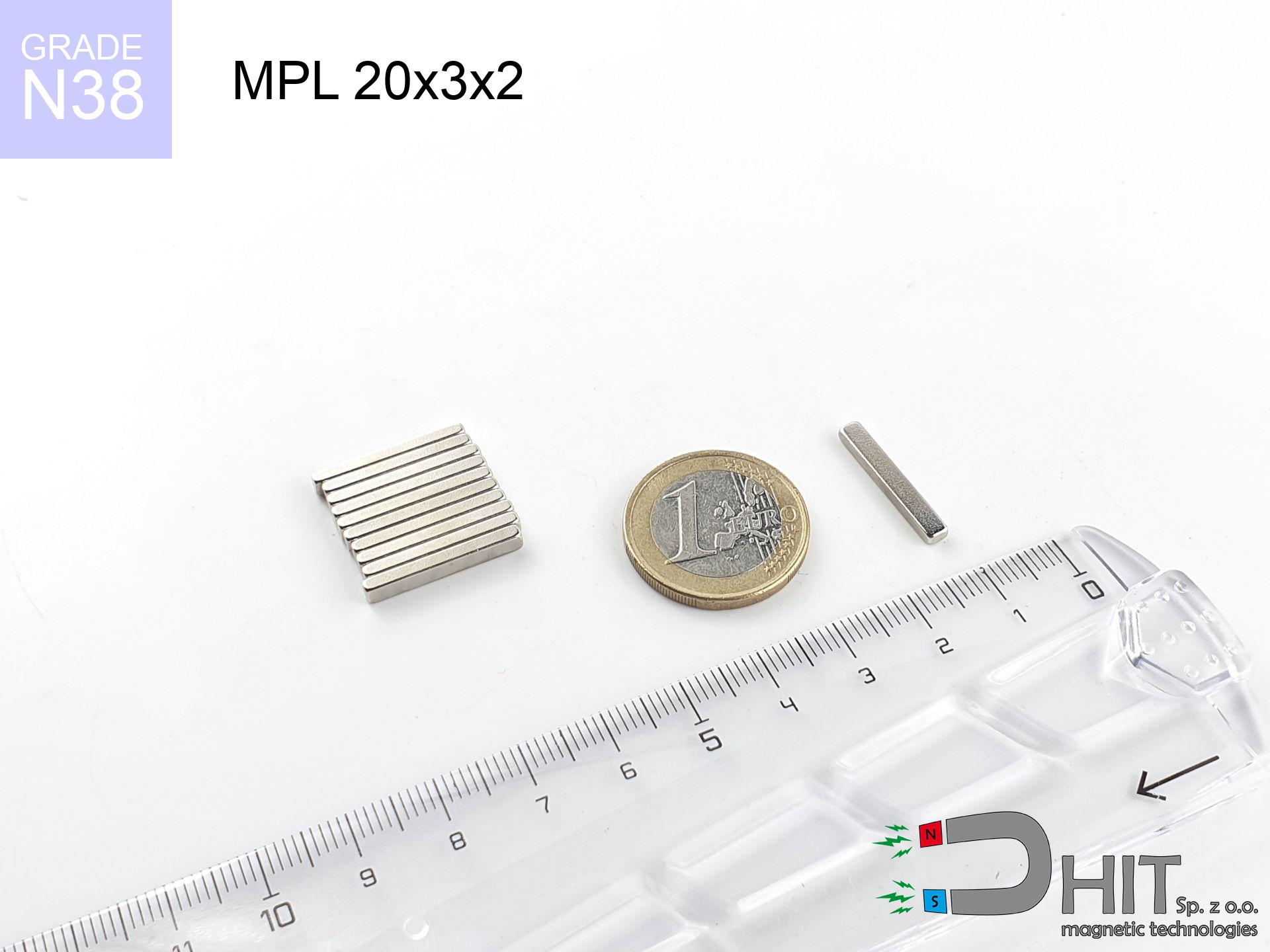
MPL 20x3x2 / N38 - lamellar magnet
lamellar magnet
Catalog no 020130
GTIN/EAN: 5906301811367
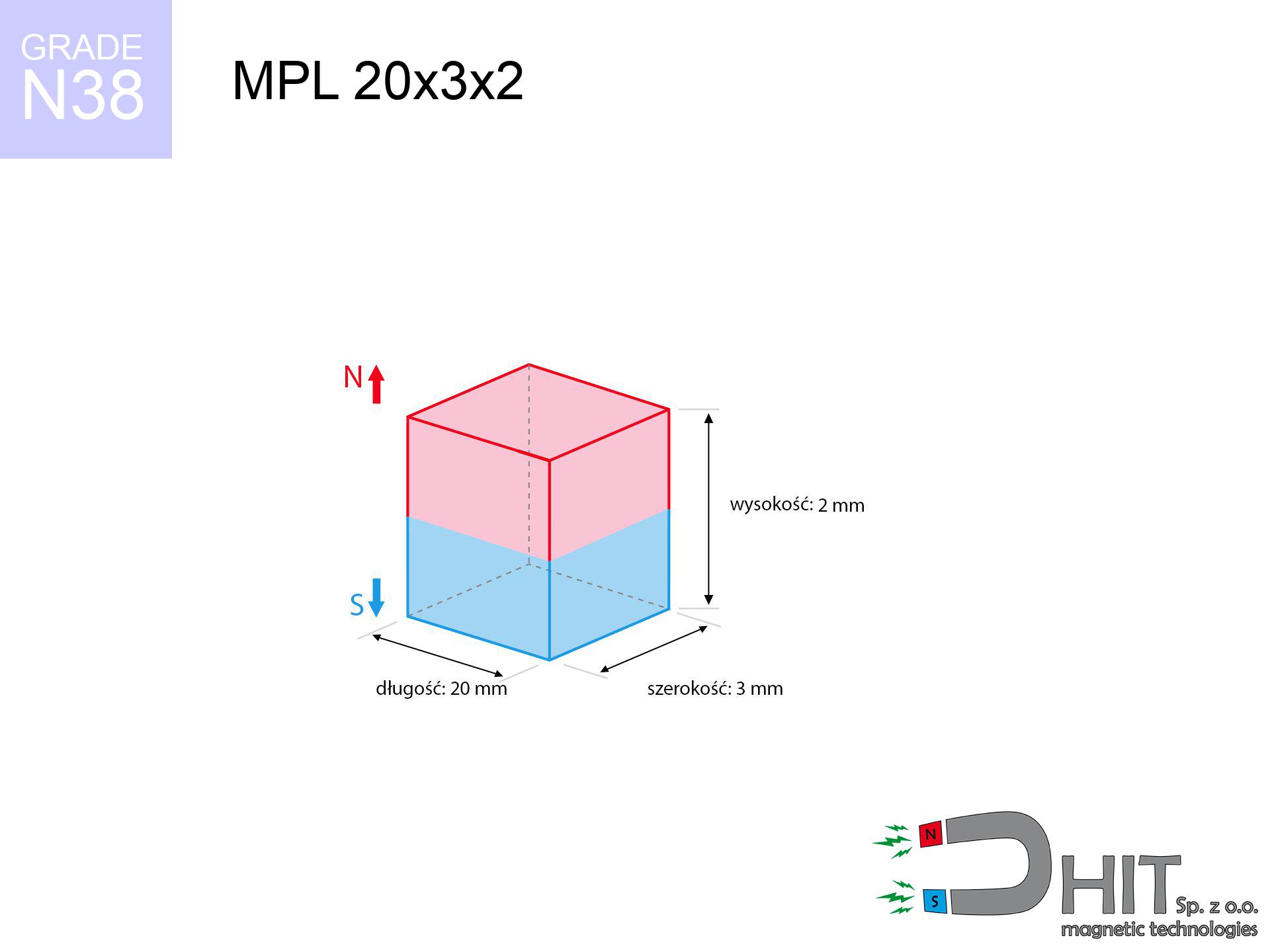
length
20 mm [±0,1 mm]
Width
3 mm [±0,1 mm]
Height
2 mm [±0,1 mm]
Weight
0.9 g
Magnetization Direction
↑ axial
Load capacity
2.33 kg / 22.90 N
Magnetic Induction
370.68 mT / 3707 Gs
Coating
[NiCuNi] Nickel
0.394 ZŁ with VAT / pcs + price for transport
0.320 ZŁ net + 23% VAT / pcs
bulk discounts:
Need more?
Call us now
+48 22 499 98 98
alternatively get in touch using
our online form
the contact page.
Parameters and appearance of neodymium magnets can be tested on our
online calculation tool.
Order by 14:00 and we’ll ship today!
Technical - MPL 20x3x2 / N38 - lamellar magnet
Specification / characteristics - MPL 20x3x2 / N38 - lamellar magnet
| properties | values |
|---|---|
| Cat. no. | 020130 |
| GTIN/EAN | 5906301811367 |
| Production/Distribution | Dhit sp. z o.o. |
| Country of origin | Poland / China / Germany |
| Customs code | 85059029 |
| length | 20 mm [±0,1 mm] |
| Width | 3 mm [±0,1 mm] |
| Height | 2 mm [±0,1 mm] |
| Weight | 0.9 g |
| Magnetization Direction | ↑ axial |
| Load capacity ~ ? | 2.33 kg / 22.90 N |
| Magnetic Induction ~ ? | 370.68 mT / 3707 Gs |
| Coating | [NiCuNi] Nickel |
| Manufacturing Tolerance | ±0.1 mm |
Magnetic properties of material N38
| properties | values | units |
|---|---|---|
| remenance Br [min. - max.] ? | 12.2-12.6 | kGs |
| remenance Br [min. - max.] ? | 1220-1260 | mT |
| coercivity bHc ? | 10.8-11.5 | kOe |
| coercivity bHc ? | 860-915 | kA/m |
| actual internal force iHc | ≥ 12 | kOe |
| actual internal force iHc | ≥ 955 | kA/m |
| energy density [min. - max.] ? | 36-38 | BH max MGOe |
| energy density [min. - max.] ? | 287-303 | BH max KJ/m |
| max. temperature ? | ≤ 80 | °C |
Physical properties of sintered neodymium magnets Nd2Fe14B at 20°C
| properties | values | units |
|---|---|---|
| Vickers hardness | ≥550 | Hv |
| Density | ≥7.4 | g/cm3 |
| Curie Temperature TC | 312 - 380 | °C |
| Curie Temperature TF | 593 - 716 | °F |
| Specific resistance | 150 | μΩ⋅cm |
| Bending strength | 250 | MPa |
| Compressive strength | 1000~1100 | MPa |
| Thermal expansion parallel (∥) to orientation (M) | (3-4) x 10-6 | °C-1 |
| Thermal expansion perpendicular (⊥) to orientation (M) | -(1-3) x 10-6 | °C-1 |
| Young's modulus | 1.7 x 10⁴ | kg/mm² |
Physical analysis of the product - data
Presented information represent the outcome of a physical calculation. Values are based on models for the material Nd2Fe14B. Real-world conditions may differ from theoretical values. Please consider these data as a preliminary roadmap during assembly planning.
Table 1: Static pull force (force vs distance) - characteristics
MPL 20x3x2 / N38
| Distance (mm) | Induction (Gauss) / mT | Pull Force (kg/lbs/g/N) | Risk Status |
|---|---|---|---|
| 0 mm |
3700 Gs
370.0 mT
|
2.33 kg / 5.14 LBS
2330.0 g / 22.9 N
|
strong |
| 1 mm |
2103 Gs
210.3 mT
|
0.75 kg / 1.66 LBS
752.3 g / 7.4 N
|
safe |
| 2 mm |
1172 Gs
117.2 mT
|
0.23 kg / 0.52 LBS
233.7 g / 2.3 N
|
safe |
| 3 mm |
721 Gs
72.1 mT
|
0.09 kg / 0.20 LBS
88.5 g / 0.9 N
|
safe |
| 5 mm |
345 Gs
34.5 mT
|
0.02 kg / 0.04 LBS
20.3 g / 0.2 N
|
safe |
| 10 mm |
101 Gs
10.1 mT
|
0.00 kg / 0.00 LBS
1.7 g / 0.0 N
|
safe |
| 15 mm |
42 Gs
4.2 mT
|
0.00 kg / 0.00 LBS
0.3 g / 0.0 N
|
safe |
| 20 mm |
21 Gs
2.1 mT
|
0.00 kg / 0.00 LBS
0.1 g / 0.0 N
|
safe |
| 30 mm |
7 Gs
0.7 mT
|
0.00 kg / 0.00 LBS
0.0 g / 0.0 N
|
safe |
| 50 mm |
2 Gs
0.2 mT
|
0.00 kg / 0.00 LBS
0.0 g / 0.0 N
|
safe |
Table 2: Slippage hold (wall)
MPL 20x3x2 / N38
| Distance (mm) | Friction coefficient | Pull Force (kg/lbs/g/N) |
|---|---|---|
| 0 mm | Stal (~0.2) |
0.47 kg / 1.03 LBS
466.0 g / 4.6 N
|
| 1 mm | Stal (~0.2) |
0.15 kg / 0.33 LBS
150.0 g / 1.5 N
|
| 2 mm | Stal (~0.2) |
0.05 kg / 0.10 LBS
46.0 g / 0.5 N
|
| 3 mm | Stal (~0.2) |
0.02 kg / 0.04 LBS
18.0 g / 0.2 N
|
| 5 mm | Stal (~0.2) |
0.00 kg / 0.01 LBS
4.0 g / 0.0 N
|
| 10 mm | Stal (~0.2) |
0.00 kg / 0.00 LBS
0.0 g / 0.0 N
|
| 15 mm | Stal (~0.2) |
0.00 kg / 0.00 LBS
0.0 g / 0.0 N
|
| 20 mm | Stal (~0.2) |
0.00 kg / 0.00 LBS
0.0 g / 0.0 N
|
| 30 mm | Stal (~0.2) |
0.00 kg / 0.00 LBS
0.0 g / 0.0 N
|
| 50 mm | Stal (~0.2) |
0.00 kg / 0.00 LBS
0.0 g / 0.0 N
|
Table 3: Wall mounting (sliding) - vertical pull
MPL 20x3x2 / N38
| Surface type | Friction coefficient / % Mocy | Max load (kg/lbs/g/N) |
|---|---|---|
| Raw steel |
µ = 0.3
30% Nominalnej Siły
|
0.70 kg / 1.54 LBS
699.0 g / 6.9 N
|
| Painted steel (standard) |
µ = 0.2
20% Nominalnej Siły
|
0.47 kg / 1.03 LBS
466.0 g / 4.6 N
|
| Oily/slippery steel |
µ = 0.1
10% Nominalnej Siły
|
0.23 kg / 0.51 LBS
233.0 g / 2.3 N
|
| Magnet with anti-slip rubber |
µ = 0.5
50% Nominalnej Siły
|
1.17 kg / 2.57 LBS
1165.0 g / 11.4 N
|
Table 4: Material efficiency (substrate influence) - power losses
MPL 20x3x2 / N38
| Steel thickness (mm) | % power | Real pull force (kg/lbs/g/N) |
|---|---|---|
| 0.5 mm |
|
0.23 kg / 0.51 LBS
233.0 g / 2.3 N
|
| 1 mm |
|
0.58 kg / 1.28 LBS
582.5 g / 5.7 N
|
| 2 mm |
|
1.17 kg / 2.57 LBS
1165.0 g / 11.4 N
|
| 3 mm |
|
1.75 kg / 3.85 LBS
1747.5 g / 17.1 N
|
| 5 mm |
|
2.33 kg / 5.14 LBS
2330.0 g / 22.9 N
|
| 10 mm |
|
2.33 kg / 5.14 LBS
2330.0 g / 22.9 N
|
| 11 mm |
|
2.33 kg / 5.14 LBS
2330.0 g / 22.9 N
|
| 12 mm |
|
2.33 kg / 5.14 LBS
2330.0 g / 22.9 N
|
Table 5: Working in heat (material behavior) - thermal limit
MPL 20x3x2 / N38
| Ambient temp. (°C) | Power loss | Remaining pull (kg/lbs/g/N) | Status |
|---|---|---|---|
| 20 °C | 0.0% |
2.33 kg / 5.14 LBS
2330.0 g / 22.9 N
|
OK |
| 40 °C | -2.2% |
2.28 kg / 5.02 LBS
2278.7 g / 22.4 N
|
OK |
| 60 °C | -4.4% |
2.23 kg / 4.91 LBS
2227.5 g / 21.9 N
|
|
| 80 °C | -6.6% |
2.18 kg / 4.80 LBS
2176.2 g / 21.3 N
|
|
| 100 °C | -28.8% |
1.66 kg / 3.66 LBS
1659.0 g / 16.3 N
|
Table 6: Two magnets (attraction) - field range
MPL 20x3x2 / N38
| Gap (mm) | Attraction (kg/lbs) (N-S) | Sliding Force (kg/lbs/g/N) | Repulsion (kg/lbs) (N-N) |
|---|---|---|---|
| 0 mm |
5.06 kg / 11.17 LBS
4 866 Gs
|
0.76 kg / 1.67 LBS
760 g / 7.5 N
|
N/A |
| 1 mm |
3.01 kg / 6.64 LBS
5 705 Gs
|
0.45 kg / 1.00 LBS
452 g / 4.4 N
|
2.71 kg / 5.97 LBS
~0 Gs
|
| 2 mm |
1.64 kg / 3.61 LBS
4 205 Gs
|
0.25 kg / 0.54 LBS
245 g / 2.4 N
|
1.47 kg / 3.24 LBS
~0 Gs
|
| 3 mm |
0.89 kg / 1.97 LBS
3 106 Gs
|
0.13 kg / 0.29 LBS
134 g / 1.3 N
|
0.80 kg / 1.77 LBS
~0 Gs
|
| 5 mm |
0.31 kg / 0.67 LBS
1 816 Gs
|
0.05 kg / 0.10 LBS
46 g / 0.4 N
|
0.27 kg / 0.61 LBS
~0 Gs
|
| 10 mm |
0.04 kg / 0.10 LBS
690 Gs
|
0.01 kg / 0.01 LBS
7 g / 0.1 N
|
0.04 kg / 0.09 LBS
~0 Gs
|
| 20 mm |
0.00 kg / 0.01 LBS
202 Gs
|
0.00 kg / 0.00 LBS
1 g / 0.0 N
|
0.00 kg / 0.00 LBS
~0 Gs
|
| 50 mm |
0.00 kg / 0.00 LBS
24 Gs
|
0.00 kg / 0.00 LBS
0 g / 0.0 N
|
0.00 kg / 0.00 LBS
~0 Gs
|
| 60 mm |
0.00 kg / 0.00 LBS
14 Gs
|
0.00 kg / 0.00 LBS
0 g / 0.0 N
|
0.00 kg / 0.00 LBS
~0 Gs
|
| 70 mm |
0.00 kg / 0.00 LBS
9 Gs
|
0.00 kg / 0.00 LBS
0 g / 0.0 N
|
0.00 kg / 0.00 LBS
~0 Gs
|
| 80 mm |
0.00 kg / 0.00 LBS
6 Gs
|
0.00 kg / 0.00 LBS
0 g / 0.0 N
|
0.00 kg / 0.00 LBS
~0 Gs
|
| 90 mm |
0.00 kg / 0.00 LBS
5 Gs
|
0.00 kg / 0.00 LBS
0 g / 0.0 N
|
0.00 kg / 0.00 LBS
~0 Gs
|
| 100 mm |
0.00 kg / 0.00 LBS
3 Gs
|
0.00 kg / 0.00 LBS
0 g / 0.0 N
|
0.00 kg / 0.00 LBS
~0 Gs
|
Table 7: Protective zones (implants) - warnings
MPL 20x3x2 / N38
| Object / Device | Limit (Gauss) / mT | Safe distance |
|---|---|---|
| Pacemaker | 5 Gs (0.5 mT) | 3.5 cm |
| Hearing aid | 10 Gs (1.0 mT) | 3.0 cm |
| Mechanical watch | 20 Gs (2.0 mT) | 2.5 cm |
| Phone / Smartphone | 40 Gs (4.0 mT) | 2.0 cm |
| Remote | 50 Gs (5.0 mT) | 1.5 cm |
| Payment card | 400 Gs (40.0 mT) | 0.5 cm |
| HDD hard drive | 600 Gs (60.0 mT) | 0.5 cm |
Table 8: Collisions (kinetic energy) - collision effects
MPL 20x3x2 / N38
| Start from (mm) | Speed (km/h) | Energy (J) | Predicted outcome |
|---|---|---|---|
| 10 mm |
51.34 km/h
(14.26 m/s)
|
0.09 J | |
| 30 mm |
88.88 km/h
(24.69 m/s)
|
0.27 J | |
| 50 mm |
114.74 km/h
(31.87 m/s)
|
0.46 J | |
| 100 mm |
162.27 km/h
(45.08 m/s)
|
0.91 J |
Table 9: Anti-corrosion coating durability
MPL 20x3x2 / N38
| Technical parameter | Value / Description |
|---|---|
| Coating type | [NiCuNi] Nickel |
| Layer structure | Nickel - Copper - Nickel |
| Layer thickness | 10-20 µm |
| Salt spray test (SST) ? | 24 h |
| Recommended environment | Indoors only (dry) |
Table 10: Electrical data (Pc)
MPL 20x3x2 / N38
| Parameter | Value | SI Unit / Description |
|---|---|---|
| Magnetic Flux | 1 748 Mx | 17.5 µWb |
| Pc Coefficient | 0.32 | Low (Flat) |
Table 11: Physics of underwater searching
MPL 20x3x2 / N38
| Environment | Effective steel pull | Effect |
|---|---|---|
| Air (land) | 2.33 kg | Standard |
| Water (riverbed) |
2.67 kg
(+0.34 kg buoyancy gain)
|
+14.5% |
1. Wall mount (shear)
*Note: On a vertical surface, the magnet holds only a fraction of its max power.
2. Efficiency vs thickness
*Thin metal sheet (e.g. computer case) drastically weakens the holding force.
3. Thermal stability
*For N38 grade, the max working temp is 80°C.
4. Demagnetization curve and operating point (B-H)
chart generated for the permeance coefficient Pc (Permeance Coefficient) = 0.32
This simulation demonstrates the magnetic stability of the selected magnet under specific geometric conditions. The solid red line represents the demagnetization curve (material potential), while the dashed blue line is the load line based on the magnet's geometry. The Pc (Permeance Coefficient), also known as the load line slope, is a dimensionless value that describes the relationship between the magnet's shape and its magnetic stability. The intersection of these two lines (the black dot) is the operating point — it determines the actual magnetic flux density generated by the magnet in this specific configuration. A higher Pc value means the magnet is more 'slender' (tall relative to its area), resulting in a higher operating point and better resistance to irreversible demagnetization caused by external fields or temperature. A value of 0.42 is relatively low (typical for flat magnets), meaning the operating point is closer to the 'knee' of the curve — caution is advised when operating at temperatures near the maximum limit to avoid strength loss.
Material specification
| iron (Fe) | 64% – 68% |
| neodymium (Nd) | 29% – 32% |
| boron (B) | 1.1% – 1.2% |
| dysprosium (Dy) | 0.5% – 2.0% |
| coating (Ni-Cu-Ni) | < 0.05% |
Environmental data
| recyclability (EoL) | 100% |
| recycled raw materials | ~10% (pre-cons) |
| carbon footprint | low / zredukowany |
| waste code (EWC) | 16 02 16 |
Other offers


![UI 40x12x7 [CA] - badge holder](https://cdn3.dhit.pl/graphics/products/ui40x12x7-vop.jpg "UI 40x12x7 [CA] - badge holder")
Pros as well as cons of Nd2Fe14B magnets.
Pros
- Their power is maintained, and after approximately ten years it drops only by ~1% (according to research),
- Neodymium magnets are characterized by exceptionally resistant to magnetic field loss caused by external magnetic fields,
- The use of an shiny coating of noble metals (nickel, gold, silver) causes the element to look better,
- Neodymium magnets ensure maximum magnetic induction on a small area, which allows for strong attraction,
- Thanks to resistance to high temperature, they are able to function (depending on the shape) even at temperatures up to 230°C and higher...
- Thanks to modularity in shaping and the capacity to adapt to client solutions,
- Key role in modern industrial fields – they are utilized in mass storage devices, electric motors, medical equipment, also other advanced devices.
- Compactness – despite small sizes they generate large force, making them ideal for precision applications
Disadvantages
- Susceptibility to cracking is one of their disadvantages. Upon strong impact they can break. We recommend keeping them in a special holder, which not only secures them against impacts but also increases their durability
- We warn that neodymium magnets can lose their strength at high temperatures. To prevent this, we advise our specialized [AH] magnets, which work effectively even at 230°C.
- When exposed to humidity, magnets usually rust. For applications outside, it is recommended to use protective magnets, such as magnets in rubber or plastics, which secure oxidation as well as corrosion.
- Due to limitations in producing nuts and complicated forms in magnets, we recommend using cover - magnetic holder.
- Potential hazard to health – tiny shards of magnets pose a threat, in case of ingestion, which gains importance in the aspect of protecting the youngest. Additionally, tiny parts of these products are able to be problematic in diagnostics medical after entering the body.
- High unit price – neodymium magnets cost more than other types of magnets (e.g. ferrite), which increases costs of application in large quantities
Holding force characteristics
Best holding force of the magnet in ideal parameters – what contributes to it?
- using a base made of mild steel, acting as a circuit closing element
- whose transverse dimension reaches at least 10 mm
- with a surface perfectly flat
- with direct contact (no coatings)
- under perpendicular application of breakaway force (90-degree angle)
- at room temperature
Impact of factors on magnetic holding capacity in practice
- Air gap (between the magnet and the plate), as even a tiny distance (e.g. 0.5 mm) results in a drastic drop in force by up to 50% (this also applies to varnish, rust or dirt).
- Pull-off angle – note that the magnet has greatest strength perpendicularly. Under sliding down, the capacity drops significantly, often to levels of 20-30% of the maximum value.
- Plate thickness – too thin plate causes magnetic saturation, causing part of the flux to be lost into the air.
- Metal type – different alloys attracts identically. High carbon content worsen the attraction effect.
- Smoothness – ideal contact is possible only on smooth steel. Any scratches and bumps create air cushions, weakening the magnet.
- Operating temperature – NdFeB sinters have a sensitivity to temperature. At higher temperatures they are weaker, and at low temperatures they can be stronger (up to a certain limit).
Lifting capacity was measured with the use of a polished steel plate of optimal thickness (min. 20 mm), under vertically applied force, in contrast under attempts to slide the magnet the holding force is lower. In addition, even a slight gap between the magnet’s surface and the plate lowers the lifting capacity.
Warnings
This is not a toy
Only for adults. Small elements pose a choking risk, causing intestinal necrosis. Store out of reach of kids and pets.
Handling rules
Handle with care. Rare earth magnets attract from a distance and connect with huge force, often faster than you can move away.
Crushing force
Pinching hazard: The attraction force is so immense that it can result in blood blisters, crushing, and even bone fractures. Protective gloves are recommended.
Demagnetization risk
Keep cool. Neodymium magnets are sensitive to heat. If you require operation above 80°C, look for HT versions (H, SH, UH).
Risk of cracking
Despite the nickel coating, the material is brittle and cannot withstand shocks. Do not hit, as the magnet may shatter into sharp, dangerous pieces.
Metal Allergy
Nickel alert: The nickel-copper-nickel coating consists of nickel. If skin irritation occurs, cease working with magnets and wear gloves.
Data carriers
Do not bring magnets close to a wallet, laptop, or TV. The magnetism can irreversibly ruin these devices and erase data from cards.
GPS Danger
Remember: neodymium magnets generate a field that confuses precision electronics. Maintain a separation from your mobile, tablet, and navigation systems.
Danger to pacemakers
Patients with a pacemaker must keep an safe separation from magnets. The magnetic field can disrupt the operation of the life-saving device.
Dust is flammable
Powder produced during grinding of magnets is combustible. Do not drill into magnets unless you are an expert.
Tabela kosztu i czasu dostawy
Płatność przed wysyłką:

GLS kurier
Przesyłka będzie u Ciebie za 2-3 dni
14.99 ZŁ

InPost Paczkomaty 24/7
Przesyłka będzie u Ciebie za 1-2 dni
12.30 ZŁ
Płatność przy odbiorze (pobranie):
GLS kurier
Przesyłka będzie u Ciebie za 1-2 dni
23.00 ZŁ
Rate the product
Your rating