

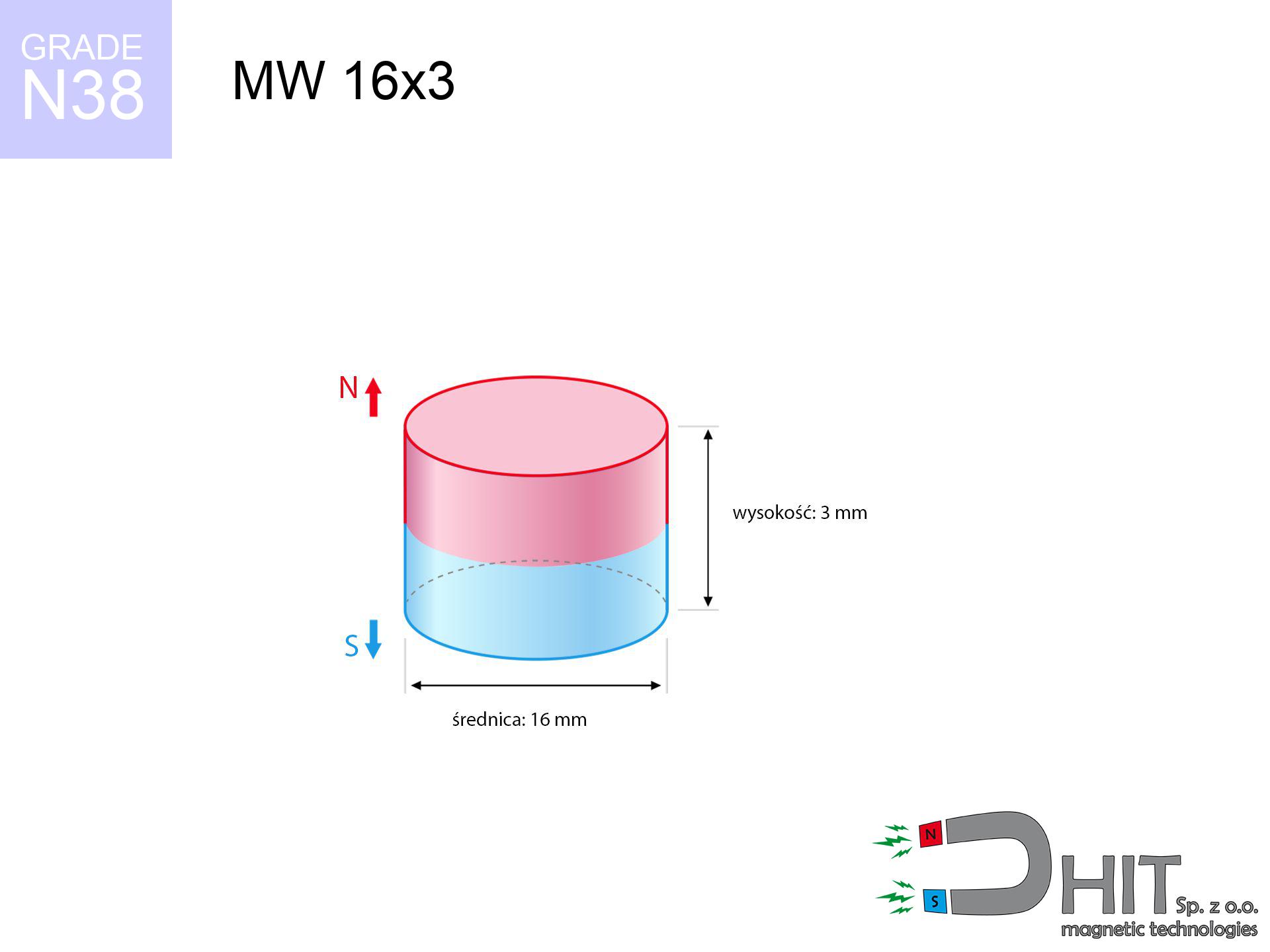
MW 16x3 / N38 - cylindrical magnet
cylindrical magnet
Catalog no 010033
GTIN/EAN: 5906301810322
Diameter Ø
16 mm [±0,1 mm]
Height
3 mm [±0,1 mm]
Weight
4.52 g
Magnetization Direction
↑ axial
Load capacity
2.97 kg / 29.11 N
Magnetic Induction
217.61 mT / 2176 Gs
Coating
[NiCuNi] Nickel
1.734 ZŁ with VAT / pcs + price for transport
1.410 ZŁ net + 23% VAT / pcs
bulk discounts:
Need more?
Give us a call
+48 888 99 98 98
alternatively contact us using
form
the contact section.
Strength along with shape of magnetic components can be checked using our
our magnetic calculator.
Orders placed before 14:00 will be shipped the same business day.
Technical specification - MW 16x3 / N38 - cylindrical magnet
Specification / characteristics - MW 16x3 / N38 - cylindrical magnet
| properties | values |
|---|---|
| Cat. no. | 010033 |
| GTIN/EAN | 5906301810322 |
| Production/Distribution | Dhit sp. z o.o. |
| Country of origin | Poland / China / Germany |
| Customs code | 85059029 |
| Diameter Ø | 16 mm [±0,1 mm] |
| Height | 3 mm [±0,1 mm] |
| Weight | 4.52 g |
| Magnetization Direction | ↑ axial |
| Load capacity ~ ? | 2.97 kg / 29.11 N |
| Magnetic Induction ~ ? | 217.61 mT / 2176 Gs |
| Coating | [NiCuNi] Nickel |
| Manufacturing Tolerance | ±0.1 mm |
Magnetic properties of material N38
| properties | values | units |
|---|---|---|
| remenance Br [min. - max.] ? | 12.2-12.6 | kGs |
| remenance Br [min. - max.] ? | 1220-1260 | mT |
| coercivity bHc ? | 10.8-11.5 | kOe |
| coercivity bHc ? | 860-915 | kA/m |
| actual internal force iHc | ≥ 12 | kOe |
| actual internal force iHc | ≥ 955 | kA/m |
| energy density [min. - max.] ? | 36-38 | BH max MGOe |
| energy density [min. - max.] ? | 287-303 | BH max KJ/m |
| max. temperature ? | ≤ 80 | °C |
Physical properties of sintered neodymium magnets Nd2Fe14B at 20°C
| properties | values | units |
|---|---|---|
| Vickers hardness | ≥550 | Hv |
| Density | ≥7.4 | g/cm3 |
| Curie Temperature TC | 312 - 380 | °C |
| Curie Temperature TF | 593 - 716 | °F |
| Specific resistance | 150 | μΩ⋅cm |
| Bending strength | 250 | MPa |
| Compressive strength | 1000~1100 | MPa |
| Thermal expansion parallel (∥) to orientation (M) | (3-4) x 10-6 | °C-1 |
| Thermal expansion perpendicular (⊥) to orientation (M) | -(1-3) x 10-6 | °C-1 |
| Young's modulus | 1.7 x 10⁴ | kg/mm² |
Technical modeling of the assembly - report
Presented values are the result of a engineering analysis. Results rely on models for the class Nd2Fe14B. Operational conditions might slightly differ. Treat these data as a supplementary guide when designing systems.
Table 1: Static pull force (force vs distance) - power drop
MW 16x3 / N38
| Distance (mm) | Induction (Gauss) / mT | Pull Force (kg/lbs/g/N) | Risk Status |
|---|---|---|---|
| 0 mm |
2176 Gs
217.6 mT
|
2.97 kg / 6.55 pounds
2970.0 g / 29.1 N
|
medium risk |
| 1 mm |
2004 Gs
200.4 mT
|
2.52 kg / 5.55 pounds
2519.3 g / 24.7 N
|
medium risk |
| 2 mm |
1782 Gs
178.2 mT
|
1.99 kg / 4.39 pounds
1993.2 g / 19.6 N
|
low risk |
| 3 mm |
1543 Gs
154.3 mT
|
1.49 kg / 3.29 pounds
1494.0 g / 14.7 N
|
low risk |
| 5 mm |
1098 Gs
109.8 mT
|
0.76 kg / 1.67 pounds
756.6 g / 7.4 N
|
low risk |
| 10 mm |
439 Gs
43.9 mT
|
0.12 kg / 0.27 pounds
120.9 g / 1.2 N
|
low risk |
| 15 mm |
195 Gs
19.5 mT
|
0.02 kg / 0.05 pounds
23.9 g / 0.2 N
|
low risk |
| 20 mm |
99 Gs
9.9 mT
|
0.01 kg / 0.01 pounds
6.2 g / 0.1 N
|
low risk |
| 30 mm |
35 Gs
3.5 mT
|
0.00 kg / 0.00 pounds
0.8 g / 0.0 N
|
low risk |
| 50 mm |
8 Gs
0.8 mT
|
0.00 kg / 0.00 pounds
0.0 g / 0.0 N
|
low risk |
Table 2: Slippage capacity (vertical surface)
MW 16x3 / N38
| Distance (mm) | Friction coefficient | Pull Force (kg/lbs/g/N) |
|---|---|---|
| 0 mm | Stal (~0.2) |
0.59 kg / 1.31 pounds
594.0 g / 5.8 N
|
| 1 mm | Stal (~0.2) |
0.50 kg / 1.11 pounds
504.0 g / 4.9 N
|
| 2 mm | Stal (~0.2) |
0.40 kg / 0.88 pounds
398.0 g / 3.9 N
|
| 3 mm | Stal (~0.2) |
0.30 kg / 0.66 pounds
298.0 g / 2.9 N
|
| 5 mm | Stal (~0.2) |
0.15 kg / 0.34 pounds
152.0 g / 1.5 N
|
| 10 mm | Stal (~0.2) |
0.02 kg / 0.05 pounds
24.0 g / 0.2 N
|
| 15 mm | Stal (~0.2) |
0.00 kg / 0.01 pounds
4.0 g / 0.0 N
|
| 20 mm | Stal (~0.2) |
0.00 kg / 0.00 pounds
2.0 g / 0.0 N
|
| 30 mm | Stal (~0.2) |
0.00 kg / 0.00 pounds
0.0 g / 0.0 N
|
| 50 mm | Stal (~0.2) |
0.00 kg / 0.00 pounds
0.0 g / 0.0 N
|
Table 3: Vertical assembly (sliding) - vertical pull
MW 16x3 / N38
| Surface type | Friction coefficient / % Mocy | Max load (kg/lbs/g/N) |
|---|---|---|
| Raw steel |
µ = 0.3
30% Nominalnej Siły
|
0.89 kg / 1.96 pounds
891.0 g / 8.7 N
|
| Painted steel (standard) |
µ = 0.2
20% Nominalnej Siły
|
0.59 kg / 1.31 pounds
594.0 g / 5.8 N
|
| Oily/slippery steel |
µ = 0.1
10% Nominalnej Siły
|
0.30 kg / 0.65 pounds
297.0 g / 2.9 N
|
| Magnet with anti-slip rubber |
µ = 0.5
50% Nominalnej Siły
|
1.49 kg / 3.27 pounds
1485.0 g / 14.6 N
|
Table 4: Steel thickness (substrate influence) - sheet metal selection
MW 16x3 / N38
| Steel thickness (mm) | % power | Real pull force (kg/lbs/g/N) |
|---|---|---|
| 0.5 mm |
|
0.30 kg / 0.65 pounds
297.0 g / 2.9 N
|
| 1 mm |
|
0.74 kg / 1.64 pounds
742.5 g / 7.3 N
|
| 2 mm |
|
1.49 kg / 3.27 pounds
1485.0 g / 14.6 N
|
| 3 mm |
|
2.23 kg / 4.91 pounds
2227.5 g / 21.9 N
|
| 5 mm |
|
2.97 kg / 6.55 pounds
2970.0 g / 29.1 N
|
| 10 mm |
|
2.97 kg / 6.55 pounds
2970.0 g / 29.1 N
|
| 11 mm |
|
2.97 kg / 6.55 pounds
2970.0 g / 29.1 N
|
| 12 mm |
|
2.97 kg / 6.55 pounds
2970.0 g / 29.1 N
|
Table 5: Thermal stability (material behavior) - thermal limit
MW 16x3 / N38
| Ambient temp. (°C) | Power loss | Remaining pull (kg/lbs/g/N) | Status |
|---|---|---|---|
| 20 °C | 0.0% |
2.97 kg / 6.55 pounds
2970.0 g / 29.1 N
|
OK |
| 40 °C | -2.2% |
2.90 kg / 6.40 pounds
2904.7 g / 28.5 N
|
OK |
| 60 °C | -4.4% |
2.84 kg / 6.26 pounds
2839.3 g / 27.9 N
|
|
| 80 °C | -6.6% |
2.77 kg / 6.12 pounds
2774.0 g / 27.2 N
|
|
| 100 °C | -28.8% |
2.11 kg / 4.66 pounds
2114.6 g / 20.7 N
|
Table 6: Two magnets (repulsion) - field range
MW 16x3 / N38
| Gap (mm) | Attraction (kg/lbs) (N-S) | Shear Force (kg/lbs/g/N) | Repulsion (kg/lbs) (N-N) |
|---|---|---|---|
| 0 mm |
5.87 kg / 12.93 pounds
3 716 Gs
|
0.88 kg / 1.94 pounds
880 g / 8.6 N
|
N/A |
| 1 mm |
5.46 kg / 12.03 pounds
4 197 Gs
|
0.82 kg / 1.80 pounds
819 g / 8.0 N
|
4.91 kg / 10.83 pounds
~0 Gs
|
| 2 mm |
4.98 kg / 10.97 pounds
4 007 Gs
|
0.75 kg / 1.65 pounds
746 g / 7.3 N
|
4.48 kg / 9.87 pounds
~0 Gs
|
| 3 mm |
4.46 kg / 9.83 pounds
3 794 Gs
|
0.67 kg / 1.48 pounds
669 g / 6.6 N
|
4.01 kg / 8.85 pounds
~0 Gs
|
| 5 mm |
3.43 kg / 7.56 pounds
3 326 Gs
|
0.51 kg / 1.13 pounds
514 g / 5.0 N
|
3.09 kg / 6.80 pounds
~0 Gs
|
| 10 mm |
1.49 kg / 3.30 pounds
2 196 Gs
|
0.22 kg / 0.49 pounds
224 g / 2.2 N
|
1.35 kg / 2.97 pounds
~0 Gs
|
| 20 mm |
0.24 kg / 0.53 pounds
878 Gs
|
0.04 kg / 0.08 pounds
36 g / 0.4 N
|
0.21 kg / 0.47 pounds
~0 Gs
|
| 50 mm |
0.00 kg / 0.01 pounds
113 Gs
|
0.00 kg / 0.00 pounds
1 g / 0.0 N
|
0.00 kg / 0.00 pounds
~0 Gs
|
| 60 mm |
0.00 kg / 0.00 pounds
70 Gs
|
0.00 kg / 0.00 pounds
0 g / 0.0 N
|
0.00 kg / 0.00 pounds
~0 Gs
|
| 70 mm |
0.00 kg / 0.00 pounds
46 Gs
|
0.00 kg / 0.00 pounds
0 g / 0.0 N
|
0.00 kg / 0.00 pounds
~0 Gs
|
| 80 mm |
0.00 kg / 0.00 pounds
32 Gs
|
0.00 kg / 0.00 pounds
0 g / 0.0 N
|
0.00 kg / 0.00 pounds
~0 Gs
|
| 90 mm |
0.00 kg / 0.00 pounds
23 Gs
|
0.00 kg / 0.00 pounds
0 g / 0.0 N
|
0.00 kg / 0.00 pounds
~0 Gs
|
| 100 mm |
0.00 kg / 0.00 pounds
17 Gs
|
0.00 kg / 0.00 pounds
0 g / 0.0 N
|
0.00 kg / 0.00 pounds
~0 Gs
|
Table 7: Safety (HSE) (electronics) - precautionary measures
MW 16x3 / N38
| Object / Device | Limit (Gauss) / mT | Safe distance |
|---|---|---|
| Pacemaker | 5 Gs (0.5 mT) | 6.0 cm |
| Hearing aid | 10 Gs (1.0 mT) | 5.0 cm |
| Timepiece | 20 Gs (2.0 mT) | 4.0 cm |
| Mobile device | 40 Gs (4.0 mT) | 3.0 cm |
| Remote | 50 Gs (5.0 mT) | 3.0 cm |
| Payment card | 400 Gs (40.0 mT) | 1.5 cm |
| HDD hard drive | 600 Gs (60.0 mT) | 1.0 cm |
Table 8: Impact energy (kinetic energy) - collision effects
MW 16x3 / N38
| Start from (mm) | Speed (km/h) | Energy (J) | Predicted outcome |
|---|---|---|---|
| 10 mm |
26.50 km/h
(7.36 m/s)
|
0.12 J | |
| 30 mm |
44.78 km/h
(12.44 m/s)
|
0.35 J | |
| 50 mm |
57.81 km/h
(16.06 m/s)
|
0.58 J | |
| 100 mm |
81.75 km/h
(22.71 m/s)
|
1.17 J |
Table 9: Corrosion resistance
MW 16x3 / N38
| Technical parameter | Value / Description |
|---|---|
| Coating type | [NiCuNi] Nickel |
| Layer structure | Nickel - Copper - Nickel |
| Layer thickness | 10-20 µm |
| Salt spray test (SST) ? | 24 h |
| Recommended environment | Indoors only (dry) |
Table 10: Construction data (Pc)
MW 16x3 / N38
| Parameter | Value | SI Unit / Description |
|---|---|---|
| Magnetic Flux | 5 141 Mx | 51.4 µWb |
| Pc Coefficient | 0.27 | Low (Flat) |
Table 11: Submerged application
MW 16x3 / N38
| Environment | Effective steel pull | Effect |
|---|---|---|
| Air (land) | 2.97 kg | Standard |
| Water (riverbed) |
3.40 kg
(+0.43 kg buoyancy gain)
|
+14.5% |
1. Sliding resistance
*Caution: On a vertical wall, the magnet holds only a fraction of its nominal pull.
2. Steel saturation
*Thin metal sheet (e.g. 0.5mm PC case) severely limits the holding force.
3. Heat tolerance
*For standard magnets, the max working temp is 80°C.
4. Demagnetization curve and operating point (B-H)
chart generated for the permeance coefficient Pc (Permeance Coefficient) = 0.27
This simulation demonstrates the magnetic stability of the selected magnet under specific geometric conditions. The solid red line represents the demagnetization curve (material potential), while the dashed blue line is the load line based on the magnet's geometry. The Pc (Permeance Coefficient), also known as the load line slope, is a dimensionless value that describes the relationship between the magnet's shape and its magnetic stability. The intersection of these two lines (the black dot) is the operating point — it determines the actual magnetic flux density generated by the magnet in this specific configuration. A higher Pc value means the magnet is more 'slender' (tall relative to its area), resulting in a higher operating point and better resistance to irreversible demagnetization caused by external fields or temperature. A value of 0.42 is relatively low (typical for flat magnets), meaning the operating point is closer to the 'knee' of the curve — caution is advised when operating at temperatures near the maximum limit to avoid strength loss.
Elemental analysis
| iron (Fe) | 64% – 68% |
| neodymium (Nd) | 29% – 32% |
| boron (B) | 1.1% – 1.2% |
| dysprosium (Dy) | 0.5% – 2.0% |
| coating (Ni-Cu-Ni) | < 0.05% |
Environmental data
| recyclability (EoL) | 100% |
| recycled raw materials | ~10% (pre-cons) |
| carbon footprint | low / zredukowany |
| waste code (EWC) | 16 02 16 |
View more proposals


Pros and cons of neodymium magnets.
Pros
- They virtually do not lose power, because even after ten years the decline in efficiency is only ~1% (based on calculations),
- They do not lose their magnetic properties even under close interference source,
- Thanks to the glossy finish, the coating of Ni-Cu-Ni, gold-plated, or silver-plated gives an visually attractive appearance,
- Neodymium magnets achieve maximum magnetic induction on a small surface, which ensures high operational effectiveness,
- Made from properly selected components, these magnets show impressive resistance to high heat, enabling them to function (depending on their form) at temperatures up to 230°C and above...
- Possibility of accurate creating as well as adjusting to concrete requirements,
- Huge importance in high-tech industry – they are utilized in mass storage devices, brushless drives, diagnostic systems, as well as multitasking production systems.
- Compactness – despite small sizes they generate large force, making them ideal for precision applications
Disadvantages
- Susceptibility to cracking is one of their disadvantages. Upon strong impact they can fracture. We advise keeping them in a steel housing, which not only protects them against impacts but also raises their durability
- Neodymium magnets decrease their power under the influence of heating. As soon as 80°C is exceeded, many of them start losing their force. Therefore, we recommend our special magnets marked [AH], which maintain stability even at temperatures up to 230°C
- Due to the susceptibility of magnets to corrosion in a humid environment, we recommend using waterproof magnets made of rubber, plastic or other material resistant to moisture, when using outdoors
- We suggest casing - magnetic mount, due to difficulties in creating threads inside the magnet and complex shapes.
- Potential hazard to health – tiny shards of magnets can be dangerous, in case of ingestion, which becomes key in the context of child safety. Furthermore, small elements of these magnets can disrupt the diagnostic process medical after entering the body.
- Higher cost of purchase is one of the disadvantages compared to ceramic magnets, especially in budget applications
Holding force characteristics
Optimal lifting capacity of a neodymium magnet – what contributes to it?
- with the use of a yoke made of special test steel, guaranteeing full magnetic saturation
- with a thickness of at least 10 mm
- with an ground contact surface
- under conditions of no distance (metal-to-metal)
- during detachment in a direction perpendicular to the mounting surface
- at ambient temperature approx. 20 degrees Celsius
Lifting capacity in practice – influencing factors
- Gap (between the magnet and the plate), since even a very small clearance (e.g. 0.5 mm) can cause a reduction in force by up to 50% (this also applies to paint, rust or debris).
- Load vector – highest force is obtained only during perpendicular pulling. The force required to slide of the magnet along the plate is standardly many times smaller (approx. 1/5 of the lifting capacity).
- Element thickness – for full efficiency, the steel must be adequately massive. Paper-thin metal limits the attraction force (the magnet "punches through" it).
- Steel type – low-carbon steel attracts best. Alloy steels decrease magnetic properties and lifting capacity.
- Smoothness – ideal contact is obtained only on smooth steel. Rough texture create air cushions, weakening the magnet.
- Operating temperature – NdFeB sinters have a negative temperature coefficient. When it is hot they are weaker, and at low temperatures they can be stronger (up to a certain limit).
Lifting capacity testing was conducted on plates with a smooth surface of optimal thickness, under perpendicular forces, whereas under shearing force the load capacity is reduced by as much as 5 times. In addition, even a minimal clearance between the magnet and the plate lowers the holding force.
Safety rules for work with NdFeB magnets
Bodily injuries
Mind your fingers. Two large magnets will join instantly with a force of several hundred kilograms, destroying everything in their path. Be careful!
Allergic reactions
Certain individuals suffer from a hypersensitivity to Ni, which is the common plating for NdFeB magnets. Prolonged contact may cause skin redness. We recommend use safety gloves.
No play value
NdFeB magnets are not intended for children. Eating several magnets can lead to them pinching intestinal walls, which constitutes a critical condition and requires immediate surgery.
Keep away from computers
Do not bring magnets near a wallet, computer, or TV. The magnetism can irreversibly ruin these devices and wipe information from cards.
Precision electronics
Note: rare earth magnets generate a field that interferes with sensitive sensors. Maintain a safe distance from your phone, tablet, and navigation systems.
Machining danger
Machining of neodymium magnets carries a risk of fire risk. Magnetic powder oxidizes rapidly with oxygen and is hard to extinguish.
Heat sensitivity
Regular neodymium magnets (N-type) lose magnetization when the temperature exceeds 80°C. The loss of strength is permanent.
Medical interference
Individuals with a ICD should keep an safe separation from magnets. The magnetic field can disrupt the functioning of the implant.
Immense force
Before use, check safety instructions. Uncontrolled attraction can destroy the magnet or injure your hand. Be predictive.
Eye protection
Neodymium magnets are ceramic materials, meaning they are very brittle. Clashing of two magnets leads to them breaking into shards.
Tabela kosztu i czasu dostawy
Płatność przed wysyłką:

GLS kurier
Przesyłka będzie u Ciebie za 2-3 dni
14.99 ZŁ

InPost Paczkomaty 24/7
Przesyłka będzie u Ciebie za 1-2 dni
12.30 ZŁ
Płatność przy odbiorze (pobranie):
GLS kurier
Przesyłka będzie u Ciebie za 1-2 dni
23.00 ZŁ
Rate the product
Your rating