
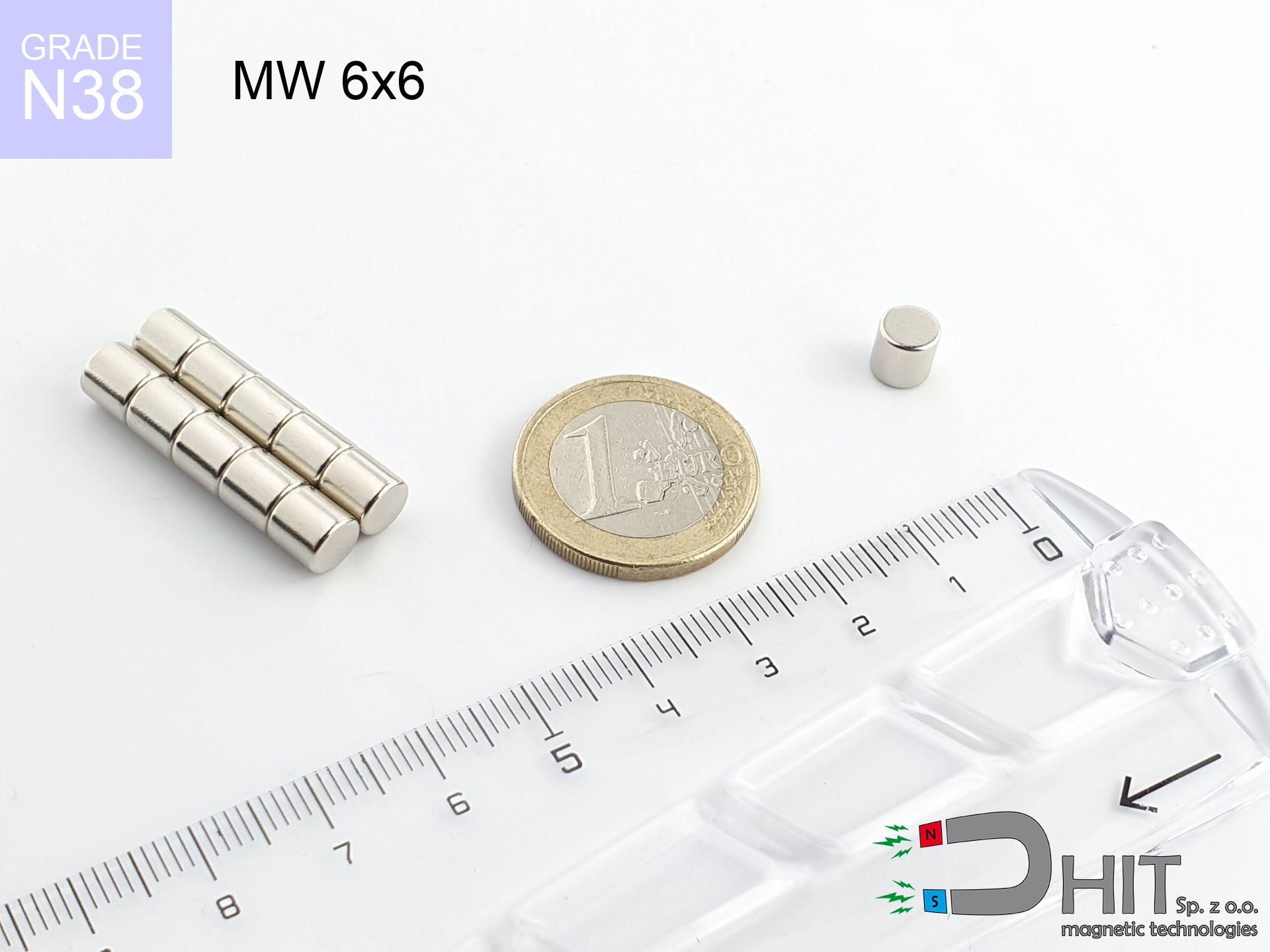
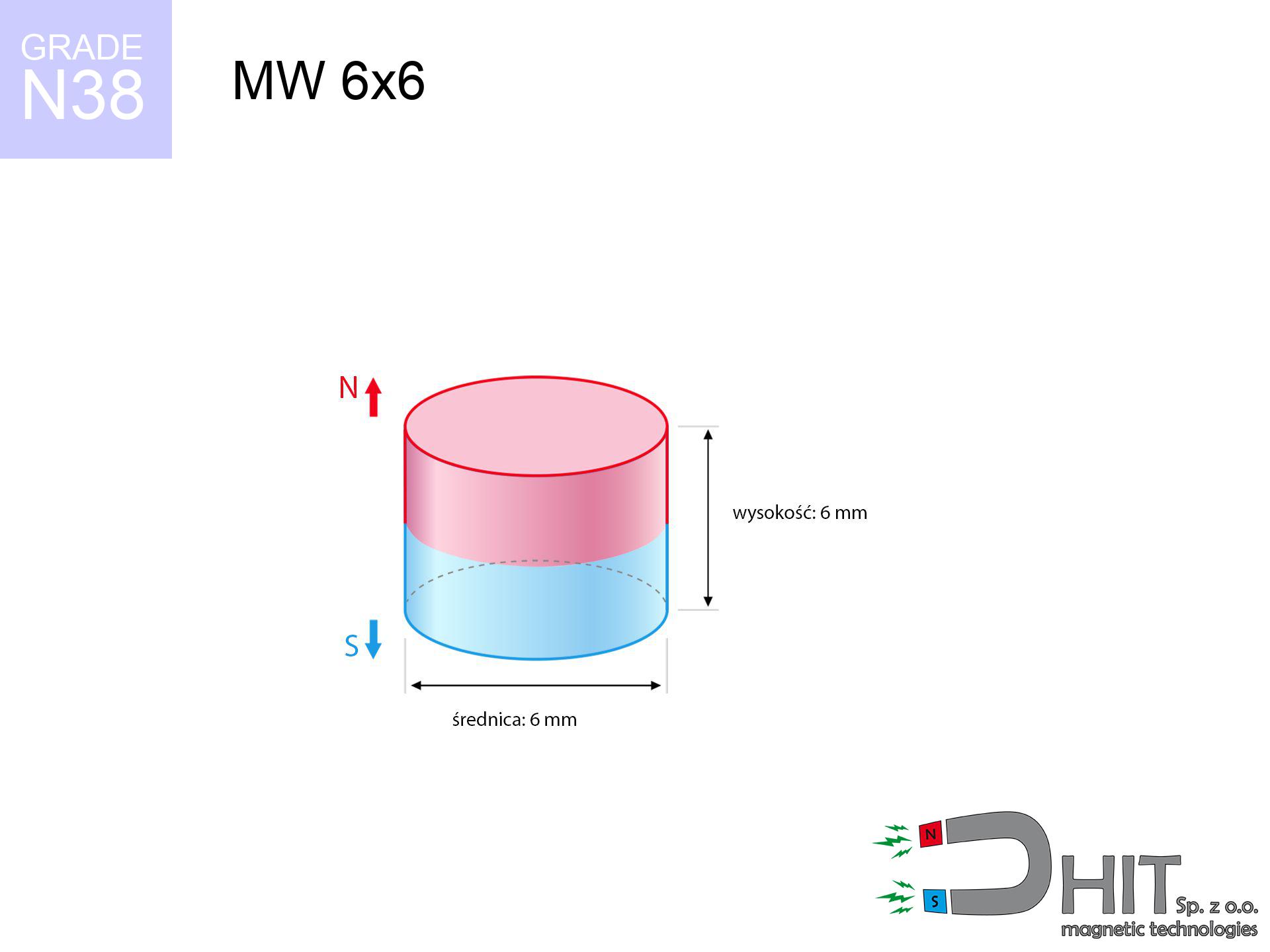
MW 6x6 / N38 - cylindrical magnet
cylindrical magnet
Catalog no 010094
GTIN/EAN: 5906301810933
Diameter Ø
6 mm [±0,1 mm]
Height
6 mm [±0,1 mm]
Weight
1.27 g
Magnetization Direction
↑ axial
Load capacity
1.14 kg / 11.18 N
Magnetic Induction
553.38 mT / 5534 Gs
Coating
[NiCuNi] Nickel
0.677 ZŁ with VAT / pcs + price for transport
0.550 ZŁ net + 23% VAT / pcs
bulk discounts:
Need more?Engineering report for this magnet
Full PDF analysis: pull and shear force, effect of distance, temperature and plate thickness, safety distances and the demagnetization curve.
Call us now
+48 22 499 98 98
otherwise drop us a message by means of
contact form
the contact form page.
Strength along with shape of magnets can be checked on our
online calculation tool.
Same-day shipping for orders placed before 14:00.
Technical of the product - MW 6x6 / N38 - cylindrical magnet
Specification / characteristics - MW 6x6 / N38 - cylindrical magnet
| properties | values |
|---|---|
| Cat. no. | 010094 |
| GTIN/EAN | 5906301810933 |
| Production/Distribution | Dhit sp. z o.o. |
| Country of origin | Poland / China / Germany |
| Customs code | 85059029 |
| Diameter Ø | 6 mm [±0,1 mm] |
| Height | 6 mm [±0,1 mm] |
| Weight | 1.27 g |
| Magnetization Direction | ↑ axial |
| Load capacity ~ ? | 1.14 kg / 11.18 N |
| Magnetic Induction ~ ? | 553.38 mT / 5534 Gs |
| Coating | [NiCuNi] Nickel |
| Manufacturing Tolerance | ±0.1 mm |
Magnetic properties of material N38
| properties | values | units |
|---|---|---|
| remenance Br [min. - max.] ? | 12.2-12.6 | kGs |
| remenance Br [min. - max.] ? | 1220-1260 | mT |
| coercivity bHc ? | 10.8-11.5 | kOe |
| coercivity bHc ? | 860-915 | kA/m |
| actual internal force iHc | ≥ 12 | kOe |
| actual internal force iHc | ≥ 955 | kA/m |
| energy density [min. - max.] ? | 36-38 | BH max MGOe |
| energy density [min. - max.] ? | 287-303 | BH max KJ/m |
| max. temperature ? | ≤ 80 | °C |
Physical properties of sintered neodymium magnets Nd2Fe14B at 20°C
| properties | values | units |
|---|---|---|
| Vickers hardness | ≥550 | Hv |
| Density | ≥7.4 | g/cm3 |
| Curie Temperature TC | 312 - 380 | °C |
| Curie Temperature TF | 593 - 716 | °F |
| Specific resistance | 150 | μΩ⋅cm |
| Bending strength | 250 | MPa |
| Compressive strength | 1000~1100 | MPa |
| Thermal expansion parallel (∥) to orientation (M) | (3-4) x 10-6 | °C-1 |
| Thermal expansion perpendicular (⊥) to orientation (M) | -(1-3) x 10-6 | °C-1 |
| Young's modulus | 1.7 x 10⁴ | kg/mm² |
Technical modeling of the magnet - technical parameters
These values are the outcome of a mathematical calculation. Results rely on models for the material Nd2Fe14B. Operational parameters may differ. Use these calculations as a reference point for designers.
Table 1: Static force (force vs gap) - interaction chart
MW 6x6 / N38
| Distance (mm) | Induction (Gauss) / mT | Pull Force (kg/lbs/g/N) | Risk Status |
|---|---|---|---|
| 0 mm |
5527 Gs
552.7 mT
|
1.14 kg / 2.51 lbs
1140.0 g / 11.2 N
|
low risk |
| 1 mm |
3738 Gs
373.8 mT
|
0.52 kg / 1.15 lbs
521.5 g / 5.1 N
|
low risk |
| 2 mm |
2366 Gs
236.6 mT
|
0.21 kg / 0.46 lbs
209.0 g / 2.0 N
|
low risk |
| 3 mm |
1498 Gs
149.8 mT
|
0.08 kg / 0.18 lbs
83.7 g / 0.8 N
|
low risk |
| 5 mm |
665 Gs
66.5 mT
|
0.02 kg / 0.04 lbs
16.5 g / 0.2 N
|
low risk |
| 10 mm |
155 Gs
15.5 mT
|
0.00 kg / 0.00 lbs
0.9 g / 0.0 N
|
low risk |
| 15 mm |
58 Gs
5.8 mT
|
0.00 kg / 0.00 lbs
0.1 g / 0.0 N
|
low risk |
| 20 mm |
28 Gs
2.8 mT
|
0.00 kg / 0.00 lbs
0.0 g / 0.0 N
|
low risk |
| 30 mm |
9 Gs
0.9 mT
|
0.00 kg / 0.00 lbs
0.0 g / 0.0 N
|
low risk |
| 50 mm |
2 Gs
0.2 mT
|
0.00 kg / 0.00 lbs
0.0 g / 0.0 N
|
low risk |
Table 2: Vertical hold (wall)
MW 6x6 / N38
| Distance (mm) | Friction coefficient | Pull Force (kg/lbs/g/N) |
|---|---|---|
| 0 mm | Stal (~0.2) |
0.23 kg / 0.50 lbs
228.0 g / 2.2 N
|
| 1 mm | Stal (~0.2) |
0.10 kg / 0.23 lbs
104.0 g / 1.0 N
|
| 2 mm | Stal (~0.2) |
0.04 kg / 0.09 lbs
42.0 g / 0.4 N
|
| 3 mm | Stal (~0.2) |
0.02 kg / 0.04 lbs
16.0 g / 0.2 N
|
| 5 mm | Stal (~0.2) |
0.00 kg / 0.01 lbs
4.0 g / 0.0 N
|
| 10 mm | Stal (~0.2) |
0.00 kg / 0.00 lbs
0.0 g / 0.0 N
|
| 15 mm | Stal (~0.2) |
0.00 kg / 0.00 lbs
0.0 g / 0.0 N
|
| 20 mm | Stal (~0.2) |
0.00 kg / 0.00 lbs
0.0 g / 0.0 N
|
| 30 mm | Stal (~0.2) |
0.00 kg / 0.00 lbs
0.0 g / 0.0 N
|
| 50 mm | Stal (~0.2) |
0.00 kg / 0.00 lbs
0.0 g / 0.0 N
|
Table 3: Vertical assembly (sliding) - behavior on slippery surfaces
MW 6x6 / N38
| Surface type | Friction coefficient / % Mocy | Max load (kg/lbs/g/N) |
|---|---|---|
| Raw steel |
µ = 0.3
30% Nominalnej Siły
|
0.34 kg / 0.75 lbs
342.0 g / 3.4 N
|
| Painted steel (standard) |
µ = 0.2
20% Nominalnej Siły
|
0.23 kg / 0.50 lbs
228.0 g / 2.2 N
|
| Oily/slippery steel |
µ = 0.1
10% Nominalnej Siły
|
0.11 kg / 0.25 lbs
114.0 g / 1.1 N
|
| Magnet with anti-slip rubber |
µ = 0.5
50% Nominalnej Siły
|
0.57 kg / 1.26 lbs
570.0 g / 5.6 N
|
Table 4: Steel thickness (saturation) - sheet metal selection
MW 6x6 / N38
| Steel thickness (mm) | % power | Real pull force (kg/lbs/g/N) |
|---|---|---|
| 0.5 mm |
|
0.11 kg / 0.25 lbs
114.0 g / 1.1 N
|
| 1 mm |
|
0.29 kg / 0.63 lbs
285.0 g / 2.8 N
|
| 2 mm |
|
0.57 kg / 1.26 lbs
570.0 g / 5.6 N
|
| 3 mm |
|
0.86 kg / 1.88 lbs
855.0 g / 8.4 N
|
| 5 mm |
|
1.14 kg / 2.51 lbs
1140.0 g / 11.2 N
|
| 10 mm |
|
1.14 kg / 2.51 lbs
1140.0 g / 11.2 N
|
| 11 mm |
|
1.14 kg / 2.51 lbs
1140.0 g / 11.2 N
|
| 12 mm |
|
1.14 kg / 2.51 lbs
1140.0 g / 11.2 N
|
Table 5: Working in heat (stability) - thermal limit
MW 6x6 / N38
| Ambient temp. (°C) | Power loss | Remaining pull (kg/lbs/g/N) | Status |
|---|---|---|---|
| 20 °C | 0.0% |
1.14 kg / 2.51 lbs
1140.0 g / 11.2 N
|
OK |
| 40 °C | -2.2% |
1.11 kg / 2.46 lbs
1114.9 g / 10.9 N
|
OK |
| 60 °C | -4.4% |
1.09 kg / 2.40 lbs
1089.8 g / 10.7 N
|
OK |
| 80 °C | -6.6% |
1.06 kg / 2.35 lbs
1064.8 g / 10.4 N
|
|
| 100 °C | -28.8% |
0.81 kg / 1.79 lbs
811.7 g / 8.0 N
|
Table 6: Magnet-Magnet interaction (repulsion) - field range
MW 6x6 / N38
| Gap (mm) | Attraction (kg/lbs) (N-S) | Shear Force (kg/lbs/g/N) | Repulsion (kg/lbs) (N-N) |
|---|---|---|---|
| 0 mm |
5.32 kg / 11.74 lbs
5 995 Gs
|
0.80 kg / 1.76 lbs
799 g / 7.8 N
|
N/A |
| 1 mm |
3.70 kg / 8.17 lbs
9 220 Gs
|
0.56 kg / 1.23 lbs
556 g / 5.5 N
|
3.33 kg / 7.35 lbs
~0 Gs
|
| 2 mm |
2.44 kg / 5.37 lbs
7 476 Gs
|
0.37 kg / 0.81 lbs
365 g / 3.6 N
|
2.19 kg / 4.83 lbs
~0 Gs
|
| 3 mm |
1.55 kg / 3.42 lbs
5 968 Gs
|
0.23 kg / 0.51 lbs
233 g / 2.3 N
|
1.40 kg / 3.08 lbs
~0 Gs
|
| 5 mm |
0.61 kg / 1.35 lbs
3 755 Gs
|
0.09 kg / 0.20 lbs
92 g / 0.9 N
|
0.55 kg / 1.22 lbs
~0 Gs
|
| 10 mm |
0.08 kg / 0.17 lbs
1 330 Gs
|
0.01 kg / 0.03 lbs
12 g / 0.1 N
|
0.07 kg / 0.15 lbs
~0 Gs
|
| 20 mm |
0.00 kg / 0.01 lbs
311 Gs
|
0.00 kg / 0.00 lbs
1 g / 0.0 N
|
0.00 kg / 0.00 lbs
~0 Gs
|
| 50 mm |
0.00 kg / 0.00 lbs
31 Gs
|
0.00 kg / 0.00 lbs
0 g / 0.0 N
|
0.00 kg / 0.00 lbs
~0 Gs
|
| 60 mm |
0.00 kg / 0.00 lbs
19 Gs
|
0.00 kg / 0.00 lbs
0 g / 0.0 N
|
0.00 kg / 0.00 lbs
~0 Gs
|
| 70 mm |
0.00 kg / 0.00 lbs
12 Gs
|
0.00 kg / 0.00 lbs
0 g / 0.0 N
|
0.00 kg / 0.00 lbs
~0 Gs
|
| 80 mm |
0.00 kg / 0.00 lbs
8 Gs
|
0.00 kg / 0.00 lbs
0 g / 0.0 N
|
0.00 kg / 0.00 lbs
~0 Gs
|
| 90 mm |
0.00 kg / 0.00 lbs
6 Gs
|
0.00 kg / 0.00 lbs
0 g / 0.0 N
|
0.00 kg / 0.00 lbs
~0 Gs
|
| 100 mm |
0.00 kg / 0.00 lbs
5 Gs
|
0.00 kg / 0.00 lbs
0 g / 0.0 N
|
0.00 kg / 0.00 lbs
~0 Gs
|
Table 7: Hazards (electronics) - precautionary measures
MW 6x6 / N38
| Object / Device | Limit (Gauss) / mT | Safe distance |
|---|---|---|
| Pacemaker | 5 Gs (0.5 mT) | 4.0 cm |
| Hearing aid | 10 Gs (1.0 mT) | 3.0 cm |
| Mechanical watch | 20 Gs (2.0 mT) | 2.5 cm |
| Mobile device | 40 Gs (4.0 mT) | 2.0 cm |
| Car key | 50 Gs (5.0 mT) | 2.0 cm |
| Payment card | 400 Gs (40.0 mT) | 1.0 cm |
| HDD hard drive | 600 Gs (60.0 mT) | 1.0 cm |
Table 8: Collisions (kinetic energy) - collision effects
MW 6x6 / N38
| Start from (mm) | Speed (km/h) | Energy (J) | Predicted outcome |
|---|---|---|---|
| 10 mm |
30.23 km/h
(8.40 m/s)
|
0.04 J | |
| 30 mm |
52.34 km/h
(14.54 m/s)
|
0.13 J | |
| 50 mm |
67.56 km/h
(18.77 m/s)
|
0.22 J | |
| 100 mm |
95.55 km/h
(26.54 m/s)
|
0.45 J |
Table 9: Surface protection spec
MW 6x6 / N38
| Technical parameter | Value / Description |
|---|---|
| Coating type | [NiCuNi] Nickel |
| Layer structure | Nickel - Copper - Nickel |
| Layer thickness | 10-20 µm |
| Salt spray test (SST) ? | 24 h |
| Recommended environment | Indoors only (dry) |
Table 10: Electrical data (Pc)
MW 6x6 / N38
| Parameter | Value | SI Unit / Description |
|---|---|---|
| Magnetic Flux | 1 613 Mx | 16.1 µWb |
| Pc Coefficient | 0.89 | High (Stable) |
Table 11: Physics of underwater searching
MW 6x6 / N38
| Environment | Effective steel pull | Effect |
|---|---|---|
| Air (land) | 1.14 kg | Standard |
| Water (riverbed) |
1.31 kg
(+0.17 kg buoyancy gain)
|
+14.5% |
1. Sliding resistance
*Note: On a vertical wall, the magnet retains only a fraction of its perpendicular strength.
2. Plate thickness effect
*Thin metal sheet (e.g. computer case) severely reduces the holding force.
3. Heat tolerance
*For N38 material, the max working temp is 80°C.
4. Demagnetization curve and operating point (B-H)
chart generated for the permeance coefficient Pc (Permeance Coefficient) = 0.89
The chart above illustrates the magnetic characteristics of the material within the second quadrant of the hysteresis loop. The solid red line represents the demagnetization curve (material potential), while the dashed blue line is the load line based on the magnet's geometry. The Pc (Permeance Coefficient), also known as the load line slope, is a dimensionless value that describes the relationship between the magnet's shape and its magnetic stability. The intersection of these two lines (the black dot) is the operating point — it determines the actual magnetic flux density generated by the magnet in this specific configuration. A higher Pc value means the magnet is more 'slender' (tall relative to its area), resulting in a higher operating point and better resistance to irreversible demagnetization caused by external fields or temperature. A value of 0.42 is relatively low (typical for flat magnets), meaning the operating point is closer to the 'knee' of the curve — caution is advised when operating at temperatures near the maximum limit to avoid strength loss.
Elemental analysis
| iron (Fe) | 64% – 68% |
| neodymium (Nd) | 29% – 32% |
| boron (B) | 1.1% – 1.2% |
| dysprosium (Dy) | 0.5% – 2.0% |
| coating (Ni-Cu-Ni) | < 0.05% |
Sustainability
| recyclability (EoL) | 100% |
| recycled raw materials | ~10% (pre-cons) |
| carbon footprint | low / zredukowany |
| waste code (EWC) | 16 02 16 |
See also deals

![MPL 40x15x5x2[7/3.5] / N38 - lamellar magnet](https://cdn3.dhit.pl/graphics/products/mpl-40x15x5x27-3.5-cas.jpg "MPL 40x15x5x2[7/3.5] / N38 - lamellar magnet")


Strengths as well as weaknesses of neodymium magnets.
Strengths
- They have constant strength, and over around 10 years their attraction force decreases symbolically – ~1% (in testing),
- They have excellent resistance to magnetic field loss when exposed to external fields,
- Thanks to the glossy finish, the coating of Ni-Cu-Ni, gold-plated, or silver-plated gives an aesthetic appearance,
- Neodymium magnets ensure maximum magnetic induction on a contact point, which increases force concentration,
- Due to their durability and thermal resistance, neodymium magnets can operate (depending on the form) even at high temperatures reaching 230°C or more...
- Thanks to versatility in forming and the capacity to modify to client solutions,
- Fundamental importance in electronics industry – they serve a role in HDD drives, drive modules, precision medical tools, and complex engineering applications.
- Compactness – despite small sizes they offer powerful magnetic field, making them ideal for precision applications
Disadvantages
- To avoid cracks upon strong impacts, we recommend using special steel holders. Such a solution secures the magnet and simultaneously improves its durability.
- We warn that neodymium magnets can lose their power at high temperatures. To prevent this, we advise our specialized [AH] magnets, which work effectively even at 230°C.
- Magnets exposed to a humid environment can rust. Therefore while using outdoors, we advise using water-impermeable magnets made of rubber, plastic or other material protecting against moisture
- We suggest casing - magnetic mechanism, due to difficulties in realizing nuts inside the magnet and complex shapes.
- Potential hazard related to microscopic parts of magnets are risky, when accidentally swallowed, which gains importance in the context of child health protection. Furthermore, small elements of these products can disrupt the diagnostic process medical after entering the body.
- With mass production the cost of neodymium magnets is economically unviable,
Lifting parameters
Detachment force of the magnet in optimal conditions – what contributes to it?
- on a base made of mild steel, effectively closing the magnetic field
- with a cross-section minimum 10 mm
- characterized by lack of roughness
- without any clearance between the magnet and steel
- during detachment in a direction vertical to the mounting surface
- in neutral thermal conditions
Impact of factors on magnetic holding capacity in practice
- Space between surfaces – every millimeter of separation (caused e.g. by veneer or unevenness) drastically reduces the pulling force, often by half at just 0.5 mm.
- Pull-off angle – note that the magnet holds strongest perpendicularly. Under shear forces, the capacity drops drastically, often to levels of 20-30% of the nominal value.
- Substrate thickness – to utilize 100% power, the steel must be sufficiently thick. Thin sheet restricts the attraction force (the magnet "punches through" it).
- Steel grade – the best choice is high-permeability steel. Hardened steels may attract less.
- Plate texture – smooth surfaces ensure maximum contact, which increases field saturation. Rough surfaces reduce efficiency.
- Temperature – heating the magnet causes a temporary drop of force. Check the maximum operating temperature for a given model.
Holding force was checked on a smooth steel plate of 20 mm thickness, when the force acted perpendicularly, in contrast under shearing force the load capacity is reduced by as much as fivefold. In addition, even a small distance between the magnet and the plate lowers the holding force.
Warnings
Safe operation
Before starting, read the rules. Sudden snapping can break the magnet or injure your hand. Think ahead.
Medical interference
Individuals with a heart stimulator should maintain an large gap from magnets. The magnetism can disrupt the functioning of the implant.
Threat to electronics
Data protection: Neodymium magnets can damage data carriers and sensitive devices (heart implants, medical aids, timepieces).
Risk of cracking
Neodymium magnets are sintered ceramics, which means they are very brittle. Collision of two magnets will cause them cracking into small pieces.
Metal Allergy
Some people experience a hypersensitivity to nickel, which is the standard coating for NdFeB magnets. Extended handling can result in a rash. It is best to wear safety gloves.
No play value
Absolutely keep magnets out of reach of children. Choking hazard is high, and the consequences of magnets clamping inside the body are tragic.
Thermal limits
Control the heat. Heating the magnet above 80 degrees Celsius will ruin its magnetic structure and pulling force.
Bodily injuries
Watch your fingers. Two powerful magnets will join immediately with a force of several hundred kilograms, destroying anything in their path. Exercise extreme caution!
Fire warning
Machining of NdFeB material poses a fire hazard. Neodymium dust oxidizes rapidly with oxygen and is difficult to extinguish.
Impact on smartphones
Navigation devices and smartphones are highly susceptible to magnetism. Close proximity with a strong magnet can ruin the internal compass in your phone.
Tabela kosztu i czasu dostawy
Płatność przed wysyłką:

GLS kurier
Przesyłka będzie u Ciebie za 2-3 dni
14.99 ZŁ

InPost Paczkomaty 24/7
Przesyłka będzie u Ciebie za 1-2 dni
12.30 ZŁ
Płatność przy odbiorze (pobranie):
GLS kurier
Przesyłka będzie u Ciebie za 1-2 dni
23.00 ZŁ
Rate the product
Your rating