
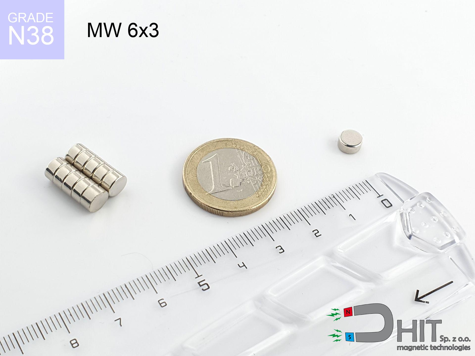
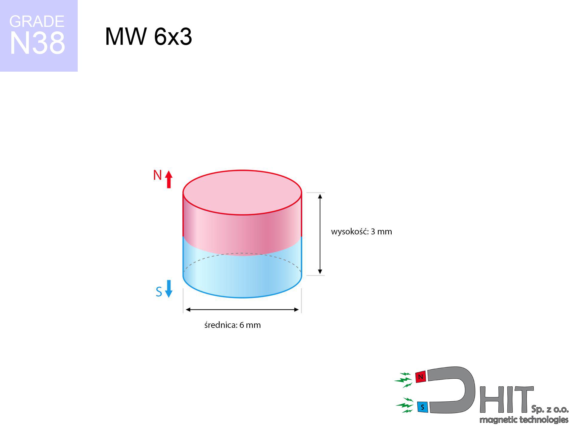
MW 6x3 / N38 - cylindrical magnet
cylindrical magnet
Catalog no 010093
GTIN/EAN: 5906301810926
Diameter Ø
6 mm [±0,1 mm]
Height
3 mm [±0,1 mm]
Weight
0.64 g
Magnetization Direction
↑ axial
Load capacity
1.15 kg / 11.23 N
Magnetic Induction
437.58 mT / 4376 Gs
Coating
[NiCuNi] Nickel
0.381 ZŁ with VAT / pcs + price for transport
0.310 ZŁ net + 23% VAT / pcs
bulk discounts:
Need more?
Call us now
+48 22 499 98 98
alternatively get in touch by means of
form
our website.
Lifting power as well as shape of neodymium magnets can be analyzed with our
magnetic calculator.
Same-day processing for orders placed before 14:00.
Technical of the product - MW 6x3 / N38 - cylindrical magnet
Specification / characteristics - MW 6x3 / N38 - cylindrical magnet
| properties | values |
|---|---|
| Cat. no. | 010093 |
| GTIN/EAN | 5906301810926 |
| Production/Distribution | Dhit sp. z o.o. |
| Country of origin | Poland / China / Germany |
| Customs code | 85059029 |
| Diameter Ø | 6 mm [±0,1 mm] |
| Height | 3 mm [±0,1 mm] |
| Weight | 0.64 g |
| Magnetization Direction | ↑ axial |
| Load capacity ~ ? | 1.15 kg / 11.23 N |
| Magnetic Induction ~ ? | 437.58 mT / 4376 Gs |
| Coating | [NiCuNi] Nickel |
| Manufacturing Tolerance | ±0.1 mm |
Magnetic properties of material N38
| properties | values | units |
|---|---|---|
| remenance Br [min. - max.] ? | 12.2-12.6 | kGs |
| remenance Br [min. - max.] ? | 1220-1260 | mT |
| coercivity bHc ? | 10.8-11.5 | kOe |
| coercivity bHc ? | 860-915 | kA/m |
| actual internal force iHc | ≥ 12 | kOe |
| actual internal force iHc | ≥ 955 | kA/m |
| energy density [min. - max.] ? | 36-38 | BH max MGOe |
| energy density [min. - max.] ? | 287-303 | BH max KJ/m |
| max. temperature ? | ≤ 80 | °C |
Physical properties of sintered neodymium magnets Nd2Fe14B at 20°C
| properties | values | units |
|---|---|---|
| Vickers hardness | ≥550 | Hv |
| Density | ≥7.4 | g/cm3 |
| Curie Temperature TC | 312 - 380 | °C |
| Curie Temperature TF | 593 - 716 | °F |
| Specific resistance | 150 | μΩ⋅cm |
| Bending strength | 250 | MPa |
| Compressive strength | 1000~1100 | MPa |
| Thermal expansion parallel (∥) to orientation (M) | (3-4) x 10-6 | °C-1 |
| Thermal expansion perpendicular (⊥) to orientation (M) | -(1-3) x 10-6 | °C-1 |
| Young's modulus | 1.7 x 10⁴ | kg/mm² |
Engineering analysis of the magnet - data
The following values are the outcome of a physical simulation. Results rely on models for the material Nd2Fe14B. Operational parameters may differ from theoretical values. Use these data as a supplementary guide during assembly planning.
Table 1: Static pull force (pull vs distance) - power drop
MW 6x3 / N38
| Distance (mm) | Induction (Gauss) / mT | Pull Force (kg/lbs/g/N) | Risk Status |
|---|---|---|---|
| 0 mm |
4371 Gs
437.1 mT
|
1.15 kg / 2.54 pounds
1150.0 g / 11.3 N
|
weak grip |
| 1 mm |
2999 Gs
299.9 mT
|
0.54 kg / 1.19 pounds
541.6 g / 5.3 N
|
weak grip |
| 2 mm |
1877 Gs
187.7 mT
|
0.21 kg / 0.47 pounds
212.2 g / 2.1 N
|
weak grip |
| 3 mm |
1161 Gs
116.1 mT
|
0.08 kg / 0.18 pounds
81.2 g / 0.8 N
|
weak grip |
| 5 mm |
489 Gs
48.9 mT
|
0.01 kg / 0.03 pounds
14.4 g / 0.1 N
|
weak grip |
| 10 mm |
103 Gs
10.3 mT
|
0.00 kg / 0.00 pounds
0.6 g / 0.0 N
|
weak grip |
| 15 mm |
36 Gs
3.6 mT
|
0.00 kg / 0.00 pounds
0.1 g / 0.0 N
|
weak grip |
| 20 mm |
17 Gs
1.7 mT
|
0.00 kg / 0.00 pounds
0.0 g / 0.0 N
|
weak grip |
| 30 mm |
5 Gs
0.5 mT
|
0.00 kg / 0.00 pounds
0.0 g / 0.0 N
|
weak grip |
| 50 mm |
1 Gs
0.1 mT
|
0.00 kg / 0.00 pounds
0.0 g / 0.0 N
|
weak grip |
Table 2: Slippage force (vertical surface)
MW 6x3 / N38
| Distance (mm) | Friction coefficient | Pull Force (kg/lbs/g/N) |
|---|---|---|
| 0 mm | Stal (~0.2) |
0.23 kg / 0.51 pounds
230.0 g / 2.3 N
|
| 1 mm | Stal (~0.2) |
0.11 kg / 0.24 pounds
108.0 g / 1.1 N
|
| 2 mm | Stal (~0.2) |
0.04 kg / 0.09 pounds
42.0 g / 0.4 N
|
| 3 mm | Stal (~0.2) |
0.02 kg / 0.04 pounds
16.0 g / 0.2 N
|
| 5 mm | Stal (~0.2) |
0.00 kg / 0.00 pounds
2.0 g / 0.0 N
|
| 10 mm | Stal (~0.2) |
0.00 kg / 0.00 pounds
0.0 g / 0.0 N
|
| 15 mm | Stal (~0.2) |
0.00 kg / 0.00 pounds
0.0 g / 0.0 N
|
| 20 mm | Stal (~0.2) |
0.00 kg / 0.00 pounds
0.0 g / 0.0 N
|
| 30 mm | Stal (~0.2) |
0.00 kg / 0.00 pounds
0.0 g / 0.0 N
|
| 50 mm | Stal (~0.2) |
0.00 kg / 0.00 pounds
0.0 g / 0.0 N
|
Table 3: Vertical assembly (shearing) - behavior on slippery surfaces
MW 6x3 / N38
| Surface type | Friction coefficient / % Mocy | Max load (kg/lbs/g/N) |
|---|---|---|
| Raw steel |
µ = 0.3
30% Nominalnej Siły
|
0.35 kg / 0.76 pounds
345.0 g / 3.4 N
|
| Painted steel (standard) |
µ = 0.2
20% Nominalnej Siły
|
0.23 kg / 0.51 pounds
230.0 g / 2.3 N
|
| Oily/slippery steel |
µ = 0.1
10% Nominalnej Siły
|
0.11 kg / 0.25 pounds
115.0 g / 1.1 N
|
| Magnet with anti-slip rubber |
µ = 0.5
50% Nominalnej Siły
|
0.58 kg / 1.27 pounds
575.0 g / 5.6 N
|
Table 4: Steel thickness (substrate influence) - power losses
MW 6x3 / N38
| Steel thickness (mm) | % power | Real pull force (kg/lbs/g/N) |
|---|---|---|
| 0.5 mm |
|
0.11 kg / 0.25 pounds
115.0 g / 1.1 N
|
| 1 mm |
|
0.29 kg / 0.63 pounds
287.5 g / 2.8 N
|
| 2 mm |
|
0.58 kg / 1.27 pounds
575.0 g / 5.6 N
|
| 3 mm |
|
0.86 kg / 1.90 pounds
862.5 g / 8.5 N
|
| 5 mm |
|
1.15 kg / 2.54 pounds
1150.0 g / 11.3 N
|
| 10 mm |
|
1.15 kg / 2.54 pounds
1150.0 g / 11.3 N
|
| 11 mm |
|
1.15 kg / 2.54 pounds
1150.0 g / 11.3 N
|
| 12 mm |
|
1.15 kg / 2.54 pounds
1150.0 g / 11.3 N
|
Table 5: Thermal stability (material behavior) - thermal limit
MW 6x3 / N38
| Ambient temp. (°C) | Power loss | Remaining pull (kg/lbs/g/N) | Status |
|---|---|---|---|
| 20 °C | 0.0% |
1.15 kg / 2.54 pounds
1150.0 g / 11.3 N
|
OK |
| 40 °C | -2.2% |
1.12 kg / 2.48 pounds
1124.7 g / 11.0 N
|
OK |
| 60 °C | -4.4% |
1.10 kg / 2.42 pounds
1099.4 g / 10.8 N
|
|
| 80 °C | -6.6% |
1.07 kg / 2.37 pounds
1074.1 g / 10.5 N
|
|
| 100 °C | -28.8% |
0.82 kg / 1.81 pounds
818.8 g / 8.0 N
|
Table 6: Magnet-Magnet interaction (repulsion) - field collision
MW 6x3 / N38
| Gap (mm) | Attraction (kg/lbs) (N-S) | Lateral Force (kg/lbs/g/N) | Repulsion (kg/lbs) (N-N) |
|---|---|---|---|
| 0 mm |
3.33 kg / 7.34 pounds
5 527 Gs
|
0.50 kg / 1.10 pounds
499 g / 4.9 N
|
N/A |
| 1 mm |
2.37 kg / 5.23 pounds
7 376 Gs
|
0.36 kg / 0.78 pounds
356 g / 3.5 N
|
2.13 kg / 4.70 pounds
~0 Gs
|
| 2 mm |
1.57 kg / 3.46 pounds
5 999 Gs
|
0.24 kg / 0.52 pounds
235 g / 2.3 N
|
1.41 kg / 3.11 pounds
~0 Gs
|
| 3 mm |
0.99 kg / 2.19 pounds
4 772 Gs
|
0.15 kg / 0.33 pounds
149 g / 1.5 N
|
0.89 kg / 1.97 pounds
~0 Gs
|
| 5 mm |
0.38 kg / 0.83 pounds
2 948 Gs
|
0.06 kg / 0.13 pounds
57 g / 0.6 N
|
0.34 kg / 0.75 pounds
~0 Gs
|
| 10 mm |
0.04 kg / 0.09 pounds
978 Gs
|
0.01 kg / 0.01 pounds
6 g / 0.1 N
|
0.04 kg / 0.08 pounds
~0 Gs
|
| 20 mm |
0.00 kg / 0.00 pounds
205 Gs
|
0.00 kg / 0.00 pounds
0 g / 0.0 N
|
0.00 kg / 0.00 pounds
~0 Gs
|
| 50 mm |
0.00 kg / 0.00 pounds
18 Gs
|
0.00 kg / 0.00 pounds
0 g / 0.0 N
|
0.00 kg / 0.00 pounds
~0 Gs
|
| 60 mm |
0.00 kg / 0.00 pounds
11 Gs
|
0.00 kg / 0.00 pounds
0 g / 0.0 N
|
0.00 kg / 0.00 pounds
~0 Gs
|
| 70 mm |
0.00 kg / 0.00 pounds
7 Gs
|
0.00 kg / 0.00 pounds
0 g / 0.0 N
|
0.00 kg / 0.00 pounds
~0 Gs
|
| 80 mm |
0.00 kg / 0.00 pounds
5 Gs
|
0.00 kg / 0.00 pounds
0 g / 0.0 N
|
0.00 kg / 0.00 pounds
~0 Gs
|
| 90 mm |
0.00 kg / 0.00 pounds
3 Gs
|
0.00 kg / 0.00 pounds
0 g / 0.0 N
|
0.00 kg / 0.00 pounds
~0 Gs
|
| 100 mm |
0.00 kg / 0.00 pounds
2 Gs
|
0.00 kg / 0.00 pounds
0 g / 0.0 N
|
0.00 kg / 0.00 pounds
~0 Gs
|
Table 7: Safety (HSE) (implants) - warnings
MW 6x3 / N38
| Object / Device | Limit (Gauss) / mT | Safe distance |
|---|---|---|
| Pacemaker | 5 Gs (0.5 mT) | 3.5 cm |
| Hearing aid | 10 Gs (1.0 mT) | 2.5 cm |
| Mechanical watch | 20 Gs (2.0 mT) | 2.0 cm |
| Phone / Smartphone | 40 Gs (4.0 mT) | 1.5 cm |
| Car key | 50 Gs (5.0 mT) | 1.5 cm |
| Payment card | 400 Gs (40.0 mT) | 1.0 cm |
| HDD hard drive | 600 Gs (60.0 mT) | 0.5 cm |
Table 8: Collisions (cracking risk) - warning
MW 6x3 / N38
| Start from (mm) | Speed (km/h) | Energy (J) | Predicted outcome |
|---|---|---|---|
| 10 mm |
42.77 km/h
(11.88 m/s)
|
0.05 J | |
| 30 mm |
74.05 km/h
(20.57 m/s)
|
0.14 J | |
| 50 mm |
95.59 km/h
(26.55 m/s)
|
0.23 J | |
| 100 mm |
135.19 km/h
(37.55 m/s)
|
0.45 J |
Table 9: Anti-corrosion coating durability
MW 6x3 / N38
| Technical parameter | Value / Description |
|---|---|
| Coating type | [NiCuNi] Nickel |
| Layer structure | Nickel - Copper - Nickel |
| Layer thickness | 10-20 µm |
| Salt spray test (SST) ? | 24 h |
| Recommended environment | Indoors only (dry) |
Table 10: Electrical data (Flux)
MW 6x3 / N38
| Parameter | Value | SI Unit / Description |
|---|---|---|
| Magnetic Flux | 1 256 Mx | 12.6 µWb |
| Pc Coefficient | 0.59 | Low (Flat) |
Table 11: Hydrostatics and buoyancy
MW 6x3 / N38
| Environment | Effective steel pull | Effect |
|---|---|---|
| Air (land) | 1.15 kg | Standard |
| Water (riverbed) |
1.32 kg
(+0.17 kg buoyancy gain)
|
+14.5% |
1. Vertical hold
*Caution: On a vertical surface, the magnet holds merely a fraction of its max power.
2. Steel thickness impact
*Thin steel (e.g. computer case) drastically weakens the holding force.
3. Thermal stability
*For N38 material, the critical limit is 80°C.
4. Demagnetization curve and operating point (B-H)
chart generated for the permeance coefficient Pc (Permeance Coefficient) = 0.59
This simulation demonstrates the magnetic stability of the selected magnet under specific geometric conditions. The solid red line represents the demagnetization curve (material potential), while the dashed blue line is the load line based on the magnet's geometry. The Pc (Permeance Coefficient), also known as the load line slope, is a dimensionless value that describes the relationship between the magnet's shape and its magnetic stability. The intersection of these two lines (the black dot) is the operating point — it determines the actual magnetic flux density generated by the magnet in this specific configuration. A higher Pc value means the magnet is more 'slender' (tall relative to its area), resulting in a higher operating point and better resistance to irreversible demagnetization caused by external fields or temperature. A value of 0.42 is relatively low (typical for flat magnets), meaning the operating point is closer to the 'knee' of the curve — caution is advised when operating at temperatures near the maximum limit to avoid strength loss.
Chemical composition
| iron (Fe) | 64% – 68% |
| neodymium (Nd) | 29% – 32% |
| boron (B) | 1.1% – 1.2% |
| dysprosium (Dy) | 0.5% – 2.0% |
| coating (Ni-Cu-Ni) | < 0.05% |
Ecology and recycling (GPSR)
| recyclability (EoL) | 100% |
| recycled raw materials | ~10% (pre-cons) |
| carbon footprint | low / zredukowany |
| waste code (EWC) | 16 02 16 |
View more deals
![BM 750x180x70 [4x M8] - magnetic beam](https://cdn3.dhit.pl/graphics/products/bm-750x180x70-4x-m8-zif.jpg "BM 750x180x70 [4x M8] - magnetic beam")


Advantages as well as disadvantages of rare earth magnets.
Pros
- They virtually do not lose strength, because even after ten years the performance loss is only ~1% (according to literature),
- They show high resistance to demagnetization induced by presence of other magnetic fields,
- In other words, due to the glossy surface of nickel, the element becomes visually attractive,
- They are known for high magnetic induction at the operating surface, which improves attraction properties,
- Made from properly selected components, these magnets show impressive resistance to high heat, enabling them to function (depending on their form) at temperatures up to 230°C and above...
- Possibility of detailed modeling and adjusting to precise conditions,
- Wide application in advanced technology sectors – they are commonly used in mass storage devices, electromotive mechanisms, medical devices, as well as industrial machines.
- Thanks to efficiency per cm³, small magnets offer high operating force, occupying minimum space,
Limitations
- To avoid cracks upon strong impacts, we recommend using special steel housings. Such a solution protects the magnet and simultaneously improves its durability.
- We warn that neodymium magnets can reduce their power at high temperatures. To prevent this, we advise our specialized [AH] magnets, which work effectively even at 230°C.
- When exposed to humidity, magnets start to rust. For applications outside, it is recommended to use protective magnets, such as those in rubber or plastics, which prevent oxidation and corrosion.
- Limited ability of producing nuts in the magnet and complicated forms - recommended is a housing - magnetic holder.
- Health risk related to microscopic parts of magnets are risky, if swallowed, which is particularly important in the context of child safety. Additionally, tiny parts of these magnets are able to complicate diagnosis medical when they are in the body.
- Higher cost of purchase is one of the disadvantages compared to ceramic magnets, especially in budget applications
Pull force analysis
Magnetic strength at its maximum – what contributes to it?
- with the use of a sheet made of low-carbon steel, guaranteeing full magnetic saturation
- with a thickness minimum 10 mm
- characterized by smoothness
- without the slightest insulating layer between the magnet and steel
- during detachment in a direction vertical to the mounting surface
- in stable room temperature
Determinants of lifting force in real conditions
- Gap between magnet and steel – every millimeter of separation (caused e.g. by varnish or unevenness) diminishes the pulling force, often by half at just 0.5 mm.
- Direction of force – maximum parameter is available only during pulling at a 90° angle. The resistance to sliding of the magnet along the plate is typically many times smaller (approx. 1/5 of the lifting capacity).
- Base massiveness – insufficiently thick plate does not close the flux, causing part of the flux to be lost to the other side.
- Material composition – different alloys attracts identically. High carbon content worsen the interaction with the magnet.
- Plate texture – ground elements ensure maximum contact, which increases force. Uneven metal weaken the grip.
- Thermal conditions – NdFeB sinters have a negative temperature coefficient. When it is hot they are weaker, and at low temperatures they can be stronger (up to a certain limit).
Lifting capacity testing was performed on a smooth plate of suitable thickness, under a perpendicular pulling force, however under shearing force the holding force is lower. Additionally, even a small distance between the magnet’s surface and the plate decreases the holding force.
Warnings
Flammability
Fire warning: Rare earth powder is explosive. Do not process magnets in home conditions as this risks ignition.
GPS Danger
Remember: rare earth magnets produce a field that disrupts sensitive sensors. Maintain a separation from your phone, device, and GPS.
Swallowing risk
Always store magnets away from children. Risk of swallowing is high, and the consequences of magnets clamping inside the body are tragic.
Caution required
Handle magnets consciously. Their immense force can surprise even experienced users. Stay alert and do not underestimate their power.
Demagnetization risk
Standard neodymium magnets (N-type) undergo demagnetization when the temperature exceeds 80°C. This process is irreversible.
Magnet fragility
Watch out for shards. Magnets can explode upon violent connection, ejecting shards into the air. Eye protection is mandatory.
Nickel coating and allergies
Certain individuals have a sensitization to Ni, which is the standard coating for NdFeB magnets. Extended handling can result in a rash. We recommend wear protective gloves.
Medical interference
Individuals with a pacemaker should maintain an absolute distance from magnets. The magnetism can stop the functioning of the life-saving device.
Finger safety
Protect your hands. Two large magnets will join immediately with a force of several hundred kilograms, crushing anything in their path. Exercise extreme caution!
Threat to electronics
Equipment safety: Strong magnets can ruin data carriers and delicate electronics (heart implants, hearing aids, timepieces).
Tabela kosztu i czasu dostawy
Płatność przed wysyłką:

GLS kurier
Przesyłka będzie u Ciebie za 2-3 dni
14.99 ZŁ

InPost Paczkomaty 24/7
Przesyłka będzie u Ciebie za 1-2 dni
12.30 ZŁ
Płatność przy odbiorze (pobranie):
GLS kurier
Przesyłka będzie u Ciebie za 1-2 dni
23.00 ZŁ
Rate the product
Your rating