
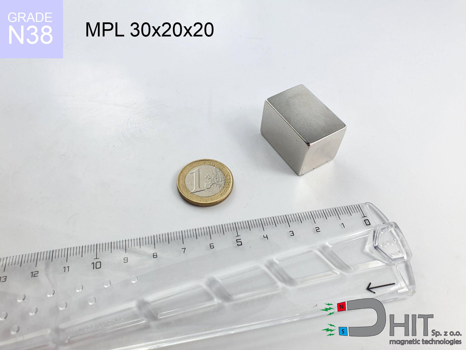
MPL 30x20x20 / N38 - lamellar magnet
lamellar magnet
Catalog no 020142
GTIN/EAN: 5906301811480
length
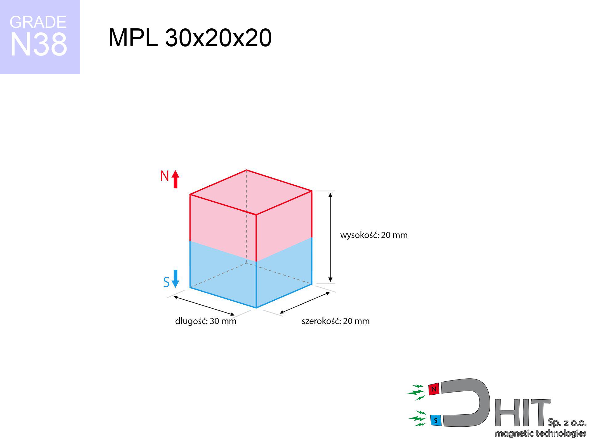
30 mm [±0,1 mm]
Width
20 mm [±0,1 mm]
Height
20 mm [±0,1 mm]
Weight
90 g
Magnetization Direction
↑ axial
Load capacity
24.27 kg / 238.07 N
Magnetic Induction
512.53 mT / 5125 Gs
Coating
[NiCuNi] Nickel
43.22 ZŁ with VAT / pcs + price for transport
35.14 ZŁ net + 23% VAT / pcs
bulk discounts:
Need more?Engineering report for this magnet
Full PDF analysis: pull and shear force, effect of distance, temperature and plate thickness, safety distances and the demagnetization curve.
Pick up the phone and ask
+48 22 499 98 98
alternatively contact us through
request form
the contact page.
Specifications as well as appearance of a neodymium magnet can be tested with our
magnetic calculator.
Same-day shipping for orders placed before 14:00.
Product card - MPL 30x20x20 / N38 - lamellar magnet
Specification / characteristics - MPL 30x20x20 / N38 - lamellar magnet
| properties | values |
|---|---|
| Cat. no. | 020142 |
| GTIN/EAN | 5906301811480 |
| Production/Distribution | Dhit sp. z o.o. |
| Country of origin | Poland / China / Germany |
| Customs code | 85059029 |
| length | 30 mm [±0,1 mm] |
| Width | 20 mm [±0,1 mm] |
| Height | 20 mm [±0,1 mm] |
| Weight | 90 g |
| Magnetization Direction | ↑ axial |
| Load capacity ~ ? | 24.27 kg / 238.07 N |
| Magnetic Induction ~ ? | 512.53 mT / 5125 Gs |
| Coating | [NiCuNi] Nickel |
| Manufacturing Tolerance | ±0.1 mm |
Magnetic properties of material N38
| properties | values | units |
|---|---|---|
| remenance Br [min. - max.] ? | 12.2-12.6 | kGs |
| remenance Br [min. - max.] ? | 1220-1260 | mT |
| coercivity bHc ? | 10.8-11.5 | kOe |
| coercivity bHc ? | 860-915 | kA/m |
| actual internal force iHc | ≥ 12 | kOe |
| actual internal force iHc | ≥ 955 | kA/m |
| energy density [min. - max.] ? | 36-38 | BH max MGOe |
| energy density [min. - max.] ? | 287-303 | BH max KJ/m |
| max. temperature ? | ≤ 80 | °C |
Physical properties of sintered neodymium magnets Nd2Fe14B at 20°C
| properties | values | units |
|---|---|---|
| Vickers hardness | ≥550 | Hv |
| Density | ≥7.4 | g/cm3 |
| Curie Temperature TC | 312 - 380 | °C |
| Curie Temperature TF | 593 - 716 | °F |
| Specific resistance | 150 | μΩ⋅cm |
| Bending strength | 250 | MPa |
| Compressive strength | 1000~1100 | MPa |
| Thermal expansion parallel (∥) to orientation (M) | (3-4) x 10-6 | °C-1 |
| Thermal expansion perpendicular (⊥) to orientation (M) | -(1-3) x 10-6 | °C-1 |
| Young's modulus | 1.7 x 10⁴ | kg/mm² |
Physical analysis of the product - data
The following values constitute the result of a physical simulation. Results rely on algorithms for the material Nd2Fe14B. Actual parameters may differ. Treat these data as a supplementary guide when designing systems.
Table 1: Static force (pull vs distance) - characteristics
MPL 30x20x20 / N38
| Distance (mm) | Induction (Gauss) / mT | Pull Force (kg/lbs/g/N) | Risk Status |
|---|---|---|---|
| 0 mm |
5124 Gs
512.4 mT
|
24.27 kg / 53.51 pounds
24270.0 g / 238.1 N
|
dangerous! |
| 1 mm |
4730 Gs
473.0 mT
|
20.68 kg / 45.60 pounds
20685.0 g / 202.9 N
|
dangerous! |
| 2 mm |
4335 Gs
433.5 mT
|
17.37 kg / 38.30 pounds
17370.7 g / 170.4 N
|
dangerous! |
| 3 mm |
3950 Gs
395.0 mT
|
14.43 kg / 31.80 pounds
14425.2 g / 141.5 N
|
dangerous! |
| 5 mm |
3240 Gs
324.0 mT
|
9.71 kg / 21.40 pounds
9706.2 g / 95.2 N
|
strong |
| 10 mm |
1923 Gs
192.3 mT
|
3.42 kg / 7.53 pounds
3417.4 g / 33.5 N
|
strong |
| 15 mm |
1163 Gs
116.3 mT
|
1.25 kg / 2.76 pounds
1250.2 g / 12.3 N
|
weak grip |
| 20 mm |
736 Gs
73.6 mT
|
0.50 kg / 1.10 pounds
500.4 g / 4.9 N
|
weak grip |
| 30 mm |
338 Gs
33.8 mT
|
0.11 kg / 0.23 pounds
105.3 g / 1.0 N
|
weak grip |
| 50 mm |
106 Gs
10.6 mT
|
0.01 kg / 0.02 pounds
10.3 g / 0.1 N
|
weak grip |
Table 2: Shear force (wall)
MPL 30x20x20 / N38
| Distance (mm) | Friction coefficient | Pull Force (kg/lbs/g/N) |
|---|---|---|
| 0 mm | Stal (~0.2) |
4.85 kg / 10.70 pounds
4854.0 g / 47.6 N
|
| 1 mm | Stal (~0.2) |
4.14 kg / 9.12 pounds
4136.0 g / 40.6 N
|
| 2 mm | Stal (~0.2) |
3.47 kg / 7.66 pounds
3474.0 g / 34.1 N
|
| 3 mm | Stal (~0.2) |
2.89 kg / 6.36 pounds
2886.0 g / 28.3 N
|
| 5 mm | Stal (~0.2) |
1.94 kg / 4.28 pounds
1942.0 g / 19.1 N
|
| 10 mm | Stal (~0.2) |
0.68 kg / 1.51 pounds
684.0 g / 6.7 N
|
| 15 mm | Stal (~0.2) |
0.25 kg / 0.55 pounds
250.0 g / 2.5 N
|
| 20 mm | Stal (~0.2) |
0.10 kg / 0.22 pounds
100.0 g / 1.0 N
|
| 30 mm | Stal (~0.2) |
0.02 kg / 0.05 pounds
22.0 g / 0.2 N
|
| 50 mm | Stal (~0.2) |
0.00 kg / 0.00 pounds
2.0 g / 0.0 N
|
Table 3: Wall mounting (sliding) - behavior on slippery surfaces
MPL 30x20x20 / N38
| Surface type | Friction coefficient / % Mocy | Max load (kg/lbs/g/N) |
|---|---|---|
| Raw steel |
µ = 0.3
30% Nominalnej Siły
|
7.28 kg / 16.05 pounds
7281.0 g / 71.4 N
|
| Painted steel (standard) |
µ = 0.2
20% Nominalnej Siły
|
4.85 kg / 10.70 pounds
4854.0 g / 47.6 N
|
| Oily/slippery steel |
µ = 0.1
10% Nominalnej Siły
|
2.43 kg / 5.35 pounds
2427.0 g / 23.8 N
|
| Magnet with anti-slip rubber |
µ = 0.5
50% Nominalnej Siły
|
12.14 kg / 26.75 pounds
12135.0 g / 119.0 N
|
Table 4: Steel thickness (substrate influence) - sheet metal selection
MPL 30x20x20 / N38
| Steel thickness (mm) | % power | Real pull force (kg/lbs/g/N) |
|---|---|---|
| 0.5 mm |
|
1.21 kg / 2.68 pounds
1213.5 g / 11.9 N
|
| 1 mm |
|
3.03 kg / 6.69 pounds
3033.8 g / 29.8 N
|
| 2 mm |
|
6.07 kg / 13.38 pounds
6067.5 g / 59.5 N
|
| 3 mm |
|
9.10 kg / 20.06 pounds
9101.3 g / 89.3 N
|
| 5 mm |
|
15.17 kg / 33.44 pounds
15168.8 g / 148.8 N
|
| 10 mm |
|
24.27 kg / 53.51 pounds
24270.0 g / 238.1 N
|
| 11 mm |
|
24.27 kg / 53.51 pounds
24270.0 g / 238.1 N
|
| 12 mm |
|
24.27 kg / 53.51 pounds
24270.0 g / 238.1 N
|
Table 5: Thermal stability (stability) - thermal limit
MPL 30x20x20 / N38
| Ambient temp. (°C) | Power loss | Remaining pull (kg/lbs/g/N) | Status |
|---|---|---|---|
| 20 °C | 0.0% |
24.27 kg / 53.51 pounds
24270.0 g / 238.1 N
|
OK |
| 40 °C | -2.2% |
23.74 kg / 52.33 pounds
23736.1 g / 232.9 N
|
OK |
| 60 °C | -4.4% |
23.20 kg / 51.15 pounds
23202.1 g / 227.6 N
|
OK |
| 80 °C | -6.6% |
22.67 kg / 49.97 pounds
22668.2 g / 222.4 N
|
|
| 100 °C | -28.8% |
17.28 kg / 38.10 pounds
17280.2 g / 169.5 N
|
Table 6: Magnet-Magnet interaction (attraction) - field collision
MPL 30x20x20 / N38
| Gap (mm) | Attraction (kg/lbs) (N-S) | Shear Force (kg/lbs/g/N) | Repulsion (kg/lbs) (N-N) |
|---|---|---|---|
| 0 mm |
97.11 kg / 214.09 pounds
5 859 Gs
|
14.57 kg / 32.11 pounds
14567 g / 142.9 N
|
N/A |
| 1 mm |
89.88 kg / 198.15 pounds
9 859 Gs
|
13.48 kg / 29.72 pounds
13482 g / 132.3 N
|
80.89 kg / 178.34 pounds
~0 Gs
|
| 2 mm |
82.77 kg / 182.47 pounds
9 461 Gs
|
12.42 kg / 27.37 pounds
12415 g / 121.8 N
|
74.49 kg / 164.22 pounds
~0 Gs
|
| 3 mm |
75.96 kg / 167.47 pounds
9 063 Gs
|
11.39 kg / 25.12 pounds
11394 g / 111.8 N
|
68.37 kg / 150.72 pounds
~0 Gs
|
| 5 mm |
63.42 kg / 139.81 pounds
8 281 Gs
|
9.51 kg / 20.97 pounds
9513 g / 93.3 N
|
57.08 kg / 125.83 pounds
~0 Gs
|
| 10 mm |
38.84 kg / 85.62 pounds
6 481 Gs
|
5.83 kg / 12.84 pounds
5826 g / 57.1 N
|
34.95 kg / 77.06 pounds
~0 Gs
|
| 20 mm |
13.67 kg / 30.15 pounds
3 845 Gs
|
2.05 kg / 4.52 pounds
2051 g / 20.1 N
|
12.31 kg / 27.13 pounds
~0 Gs
|
| 50 mm |
0.88 kg / 1.94 pounds
976 Gs
|
0.13 kg / 0.29 pounds
132 g / 1.3 N
|
0.79 kg / 1.75 pounds
~0 Gs
|
| 60 mm |
0.42 kg / 0.93 pounds
675 Gs
|
0.06 kg / 0.14 pounds
63 g / 0.6 N
|
0.38 kg / 0.84 pounds
~0 Gs
|
| 70 mm |
0.22 kg / 0.48 pounds
484 Gs
|
0.03 kg / 0.07 pounds
33 g / 0.3 N
|
0.20 kg / 0.43 pounds
~0 Gs
|
| 80 mm |
0.12 kg / 0.26 pounds
358 Gs
|
0.02 kg / 0.04 pounds
18 g / 0.2 N
|
0.11 kg / 0.24 pounds
~0 Gs
|
| 90 mm |
0.07 kg / 0.15 pounds
272 Gs
|
0.01 kg / 0.02 pounds
10 g / 0.1 N
|
0.06 kg / 0.14 pounds
~0 Gs
|
| 100 mm |
0.04 kg / 0.09 pounds
211 Gs
|
0.01 kg / 0.01 pounds
6 g / 0.1 N
|
0.04 kg / 0.08 pounds
~0 Gs
|
Table 7: Hazards (implants) - warnings
MPL 30x20x20 / N38
| Object / Device | Limit (Gauss) / mT | Safe distance |
|---|---|---|
| Pacemaker | 5 Gs (0.5 mT) | 16.0 cm |
| Hearing aid | 10 Gs (1.0 mT) | 12.5 cm |
| Timepiece | 20 Gs (2.0 mT) | 10.0 cm |
| Mobile device | 40 Gs (4.0 mT) | 7.5 cm |
| Car key | 50 Gs (5.0 mT) | 7.0 cm |
| Payment card | 400 Gs (40.0 mT) | 3.0 cm |
| HDD hard drive | 600 Gs (60.0 mT) | 2.5 cm |
Table 8: Collisions (cracking risk) - collision effects
MPL 30x20x20 / N38
| Start from (mm) | Speed (km/h) | Energy (J) | Predicted outcome |
|---|---|---|---|
| 10 mm |
17.96 km/h
(4.99 m/s)
|
1.12 J | |
| 30 mm |
28.76 km/h
(7.99 m/s)
|
2.87 J | |
| 50 mm |
37.04 km/h
(10.29 m/s)
|
4.76 J | |
| 100 mm |
52.37 km/h
(14.55 m/s)
|
9.52 J |
Table 9: Surface protection spec
MPL 30x20x20 / N38
| Technical parameter | Value / Description |
|---|---|
| Coating type | [NiCuNi] Nickel |
| Layer structure | Nickel - Copper - Nickel |
| Layer thickness | 10-20 µm |
| Salt spray test (SST) ? | 24 h |
| Recommended environment | Indoors only (dry) |
Table 10: Electrical data (Pc)
MPL 30x20x20 / N38
| Parameter | Value | SI Unit / Description |
|---|---|---|
| Magnetic Flux | 30 878 Mx | 308.8 µWb |
| Pc Coefficient | 0.74 | High (Stable) |
Table 11: Submerged application
MPL 30x20x20 / N38
| Environment | Effective steel pull | Effect |
|---|---|---|
| Air (land) | 24.27 kg | Standard |
| Water (riverbed) |
27.79 kg
(+3.52 kg buoyancy gain)
|
+14.5% |
1. Shear force
*Caution: On a vertical wall, the magnet holds just ~20% of its perpendicular strength.
2. Plate thickness effect
*Thin metal sheet (e.g. 0.5mm PC case) severely weakens the holding force.
3. Temperature resistance
*For standard magnets, the safety limit is 80°C.
4. Demagnetization curve and operating point (B-H)
chart generated for the permeance coefficient Pc (Permeance Coefficient) = 0.74
This simulation demonstrates the magnetic stability of the selected magnet under specific geometric conditions. The solid red line represents the demagnetization curve (material potential), while the dashed blue line is the load line based on the magnet's geometry. The Pc (Permeance Coefficient), also known as the load line slope, is a dimensionless value that describes the relationship between the magnet's shape and its magnetic stability. The intersection of these two lines (the black dot) is the operating point — it determines the actual magnetic flux density generated by the magnet in this specific configuration. A higher Pc value means the magnet is more 'slender' (tall relative to its area), resulting in a higher operating point and better resistance to irreversible demagnetization caused by external fields or temperature. A value of 0.42 is relatively low (typical for flat magnets), meaning the operating point is closer to the 'knee' of the curve — caution is advised when operating at temperatures near the maximum limit to avoid strength loss.
Chemical composition
| iron (Fe) | 64% – 68% |
| neodymium (Nd) | 29% – 32% |
| boron (B) | 1.1% – 1.2% |
| dysprosium (Dy) | 0.5% – 2.0% |
| coating (Ni-Cu-Ni) | < 0.05% |
Environmental data
| recyclability (EoL) | 100% |
| recycled raw materials | ~10% (pre-cons) |
| carbon footprint | low / zredukowany |
| waste code (EWC) | 16 02 16 |
See more deals
![SM 25x125 [2xM8] / N52 - magnetic separator](https://cdn3.dhit.pl/graphics/products/sm-25x125-2xm8-bub.jpg "SM 25x125 [2xM8] / N52 - magnetic separator")


Strengths as well as weaknesses of neodymium magnets.
Advantages
- They do not lose magnetism, even over nearly ten years – the decrease in strength is only ~1% (theoretically),
- They possess excellent resistance to weakening of magnetic properties when exposed to opposing magnetic fields,
- A magnet with a shiny gold surface has an effective appearance,
- The surface of neodymium magnets generates a unique magnetic field – this is one of their assets,
- Neodymium magnets are characterized by very high magnetic induction on the magnet surface and can work (depending on the shape) even at a temperature of 230°C or more...
- Considering the possibility of accurate forming and adaptation to custom needs, magnetic components can be modeled in a wide range of shapes and sizes, which amplifies use scope,
- Universal use in future technologies – they find application in HDD drives, brushless drives, diagnostic systems, as well as industrial machines.
- Thanks to efficiency per cm³, small magnets offer high operating force, occupying minimum space,
Cons
- At very strong impacts they can break, therefore we recommend placing them in strong housings. A metal housing provides additional protection against damage and increases the magnet's durability.
- NdFeB magnets lose force when exposed to high temperatures. After reaching 80°C, many of them experience permanent weakening of power (a factor is the shape and dimensions of the magnet). We offer magnets specially adapted to work at temperatures up to 230°C marked [AH], which are extremely resistant to heat
- Magnets exposed to a humid environment can corrode. Therefore during using outdoors, we suggest using water-impermeable magnets made of rubber, plastic or other material resistant to moisture
- We recommend cover - magnetic mount, due to difficulties in producing threads inside the magnet and complicated shapes.
- Possible danger resulting from small fragments of magnets pose a threat, if swallowed, which is particularly important in the context of child safety. Furthermore, tiny parts of these magnets are able to be problematic in diagnostics medical when they are in the body.
- With budget limitations the cost of neodymium magnets can be a barrier,
Lifting parameters
Magnetic strength at its maximum – what it depends on?
- using a plate made of low-carbon steel, serving as a ideal flux conductor
- whose thickness reaches at least 10 mm
- with an ideally smooth touching surface
- with zero gap (no impurities)
- during pulling in a direction perpendicular to the mounting surface
- at standard ambient temperature
Determinants of lifting force in real conditions
- Distance – existence of foreign body (paint, tape, gap) interrupts the magnetic circuit, which lowers capacity rapidly (even by 50% at 0.5 mm).
- Force direction – remember that the magnet has greatest strength perpendicularly. Under sliding down, the holding force drops drastically, often to levels of 20-30% of the maximum value.
- Substrate thickness – to utilize 100% power, the steel must be adequately massive. Paper-thin metal restricts the lifting capacity (the magnet "punches through" it).
- Steel type – low-carbon steel attracts best. Alloy steels lower magnetic permeability and holding force.
- Surface condition – ground elements guarantee perfect abutment, which increases force. Uneven metal reduce efficiency.
- Operating temperature – NdFeB sinters have a negative temperature coefficient. When it is hot they lose power, and in frost gain strength (up to a certain limit).
Lifting capacity was measured with the use of a steel plate with a smooth surface of optimal thickness (min. 20 mm), under perpendicular pulling force, in contrast under shearing force the lifting capacity is smaller. Moreover, even a minimal clearance between the magnet and the plate lowers the load capacity.
Warnings
Do not underestimate power
Before starting, read the rules. Sudden snapping can break the magnet or injure your hand. Think ahead.
Flammability
Machining of NdFeB material poses a fire hazard. Neodymium dust reacts violently with oxygen and is difficult to extinguish.
Nickel allergy
Medical facts indicate that the nickel plating (the usual finish) is a strong allergen. For allergy sufferers, refrain from direct skin contact and select versions in plastic housing.
Power loss in heat
Regular neodymium magnets (grade N) lose power when the temperature exceeds 80°C. The loss of strength is permanent.
Fragile material
Watch out for shards. Magnets can fracture upon uncontrolled impact, launching sharp fragments into the air. Eye protection is mandatory.
Adults only
Always keep magnets away from children. Ingestion danger is high, and the consequences of magnets clamping inside the body are life-threatening.
Medical interference
Warning for patients: Powerful magnets affect electronics. Maintain at least 30 cm distance or ask another person to work with the magnets.
Bodily injuries
Big blocks can crush fingers in a fraction of a second. Never place your hand betwixt two strong magnets.
Magnetic media
Avoid bringing magnets near a purse, laptop, or TV. The magnetic field can destroy these devices and erase data from cards.
GPS and phone interference
GPS units and smartphones are highly sensitive to magnetic fields. Close proximity with a powerful NdFeB magnet can decalibrate the internal compass in your phone.
Tabela kosztu i czasu dostawy
Płatność przed wysyłką:

GLS kurier
Przesyłka będzie u Ciebie za 2-3 dni
14.99 ZŁ

InPost Paczkomaty 24/7
Przesyłka będzie u Ciebie za 1-2 dni
12.30 ZŁ
Płatność przy odbiorze (pobranie):
GLS kurier
Przesyłka będzie u Ciebie za 1-2 dni
23.00 ZŁ
Rate the product
Your rating