

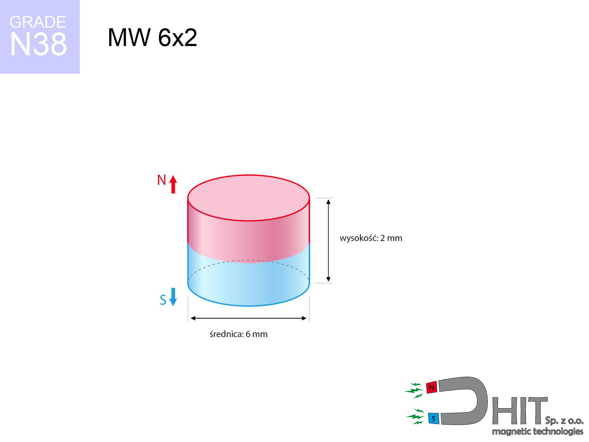
MW 6x2 / N38 - cylindrical magnet
cylindrical magnet
Catalog no 010092
GTIN/EAN: 5906301810919
Diameter Ø
6 mm [±0,1 mm]
Height
2 mm [±0,1 mm]
Weight
0.42 g
Magnetization Direction
↑ axial
Load capacity
0.86 kg / 8.43 N
Magnetic Induction
343.37 mT / 3434 Gs
Coating
[NiCuNi] Nickel
0.246 ZŁ with VAT / pcs + price for transport
0.200 ZŁ net + 23% VAT / pcs
bulk discounts:
Need more?
Call us now
+48 22 499 98 98
or contact us using
form
the contact page.
Parameters along with appearance of a neodymium magnet can be estimated using our
magnetic mass calculator.
Order by 14:00 and we’ll ship today!
Physical properties - MW 6x2 / N38 - cylindrical magnet
Specification / characteristics - MW 6x2 / N38 - cylindrical magnet
| properties | values |
|---|---|
| Cat. no. | 010092 |
| GTIN/EAN | 5906301810919 |
| Production/Distribution | Dhit sp. z o.o. |
| Country of origin | Poland / China / Germany |
| Customs code | 85059029 |
| Diameter Ø | 6 mm [±0,1 mm] |
| Height | 2 mm [±0,1 mm] |
| Weight | 0.42 g |
| Magnetization Direction | ↑ axial |
| Load capacity ~ ? | 0.86 kg / 8.43 N |
| Magnetic Induction ~ ? | 343.37 mT / 3434 Gs |
| Coating | [NiCuNi] Nickel |
| Manufacturing Tolerance | ±0.1 mm |
Magnetic properties of material N38
| properties | values | units |
|---|---|---|
| remenance Br [min. - max.] ? | 12.2-12.6 | kGs |
| remenance Br [min. - max.] ? | 1220-1260 | mT |
| coercivity bHc ? | 10.8-11.5 | kOe |
| coercivity bHc ? | 860-915 | kA/m |
| actual internal force iHc | ≥ 12 | kOe |
| actual internal force iHc | ≥ 955 | kA/m |
| energy density [min. - max.] ? | 36-38 | BH max MGOe |
| energy density [min. - max.] ? | 287-303 | BH max KJ/m |
| max. temperature ? | ≤ 80 | °C |
Physical properties of sintered neodymium magnets Nd2Fe14B at 20°C
| properties | values | units |
|---|---|---|
| Vickers hardness | ≥550 | Hv |
| Density | ≥7.4 | g/cm3 |
| Curie Temperature TC | 312 - 380 | °C |
| Curie Temperature TF | 593 - 716 | °F |
| Specific resistance | 150 | μΩ⋅cm |
| Bending strength | 250 | MPa |
| Compressive strength | 1000~1100 | MPa |
| Thermal expansion parallel (∥) to orientation (M) | (3-4) x 10-6 | °C-1 |
| Thermal expansion perpendicular (⊥) to orientation (M) | -(1-3) x 10-6 | °C-1 |
| Young's modulus | 1.7 x 10⁴ | kg/mm² |
Physical modeling of the assembly - data
These information constitute the direct effect of a mathematical analysis. Values are based on algorithms for the class Nd2Fe14B. Real-world performance might slightly differ from theoretical values. Use these calculations as a preliminary roadmap for designers.
Table 1: Static force (pull vs gap) - interaction chart
MW 6x2 / N38
| Distance (mm) | Induction (Gauss) / mT | Pull Force (kg/lbs/g/N) | Risk Status |
|---|---|---|---|
| 0 mm |
3430 Gs
343.0 mT
|
0.86 kg / 1.90 LBS
860.0 g / 8.4 N
|
weak grip |
| 1 mm |
2423 Gs
242.3 mT
|
0.43 kg / 0.95 LBS
429.2 g / 4.2 N
|
weak grip |
| 2 mm |
1521 Gs
152.1 mT
|
0.17 kg / 0.37 LBS
169.0 g / 1.7 N
|
weak grip |
| 3 mm |
932 Gs
93.2 mT
|
0.06 kg / 0.14 LBS
63.5 g / 0.6 N
|
weak grip |
| 5 mm |
382 Gs
38.2 mT
|
0.01 kg / 0.02 LBS
10.7 g / 0.1 N
|
weak grip |
| 10 mm |
76 Gs
7.6 mT
|
0.00 kg / 0.00 LBS
0.4 g / 0.0 N
|
weak grip |
| 15 mm |
26 Gs
2.6 mT
|
0.00 kg / 0.00 LBS
0.0 g / 0.0 N
|
weak grip |
| 20 mm |
12 Gs
1.2 mT
|
0.00 kg / 0.00 LBS
0.0 g / 0.0 N
|
weak grip |
| 30 mm |
4 Gs
0.4 mT
|
0.00 kg / 0.00 LBS
0.0 g / 0.0 N
|
weak grip |
| 50 mm |
1 Gs
0.1 mT
|
0.00 kg / 0.00 LBS
0.0 g / 0.0 N
|
weak grip |
Table 2: Slippage force (wall)
MW 6x2 / N38
| Distance (mm) | Friction coefficient | Pull Force (kg/lbs/g/N) |
|---|---|---|
| 0 mm | Stal (~0.2) |
0.17 kg / 0.38 LBS
172.0 g / 1.7 N
|
| 1 mm | Stal (~0.2) |
0.09 kg / 0.19 LBS
86.0 g / 0.8 N
|
| 2 mm | Stal (~0.2) |
0.03 kg / 0.07 LBS
34.0 g / 0.3 N
|
| 3 mm | Stal (~0.2) |
0.01 kg / 0.03 LBS
12.0 g / 0.1 N
|
| 5 mm | Stal (~0.2) |
0.00 kg / 0.00 LBS
2.0 g / 0.0 N
|
| 10 mm | Stal (~0.2) |
0.00 kg / 0.00 LBS
0.0 g / 0.0 N
|
| 15 mm | Stal (~0.2) |
0.00 kg / 0.00 LBS
0.0 g / 0.0 N
|
| 20 mm | Stal (~0.2) |
0.00 kg / 0.00 LBS
0.0 g / 0.0 N
|
| 30 mm | Stal (~0.2) |
0.00 kg / 0.00 LBS
0.0 g / 0.0 N
|
| 50 mm | Stal (~0.2) |
0.00 kg / 0.00 LBS
0.0 g / 0.0 N
|
Table 3: Wall mounting (shearing) - vertical pull
MW 6x2 / N38
| Surface type | Friction coefficient / % Mocy | Max load (kg/lbs/g/N) |
|---|---|---|
| Raw steel |
µ = 0.3
30% Nominalnej Siły
|
0.26 kg / 0.57 LBS
258.0 g / 2.5 N
|
| Painted steel (standard) |
µ = 0.2
20% Nominalnej Siły
|
0.17 kg / 0.38 LBS
172.0 g / 1.7 N
|
| Oily/slippery steel |
µ = 0.1
10% Nominalnej Siły
|
0.09 kg / 0.19 LBS
86.0 g / 0.8 N
|
| Magnet with anti-slip rubber |
µ = 0.5
50% Nominalnej Siły
|
0.43 kg / 0.95 LBS
430.0 g / 4.2 N
|
Table 4: Material efficiency (saturation) - power losses
MW 6x2 / N38
| Steel thickness (mm) | % power | Real pull force (kg/lbs/g/N) |
|---|---|---|
| 0.5 mm |
|
0.09 kg / 0.19 LBS
86.0 g / 0.8 N
|
| 1 mm |
|
0.22 kg / 0.47 LBS
215.0 g / 2.1 N
|
| 2 mm |
|
0.43 kg / 0.95 LBS
430.0 g / 4.2 N
|
| 3 mm |
|
0.65 kg / 1.42 LBS
645.0 g / 6.3 N
|
| 5 mm |
|
0.86 kg / 1.90 LBS
860.0 g / 8.4 N
|
| 10 mm |
|
0.86 kg / 1.90 LBS
860.0 g / 8.4 N
|
| 11 mm |
|
0.86 kg / 1.90 LBS
860.0 g / 8.4 N
|
| 12 mm |
|
0.86 kg / 1.90 LBS
860.0 g / 8.4 N
|
Table 5: Thermal resistance (stability) - resistance threshold
MW 6x2 / N38
| Ambient temp. (°C) | Power loss | Remaining pull (kg/lbs/g/N) | Status |
|---|---|---|---|
| 20 °C | 0.0% |
0.86 kg / 1.90 LBS
860.0 g / 8.4 N
|
OK |
| 40 °C | -2.2% |
0.84 kg / 1.85 LBS
841.1 g / 8.3 N
|
OK |
| 60 °C | -4.4% |
0.82 kg / 1.81 LBS
822.2 g / 8.1 N
|
|
| 80 °C | -6.6% |
0.80 kg / 1.77 LBS
803.2 g / 7.9 N
|
|
| 100 °C | -28.8% |
0.61 kg / 1.35 LBS
612.3 g / 6.0 N
|
Table 6: Two magnets (attraction) - field range
MW 6x2 / N38
| Gap (mm) | Attraction (kg/lbs) (N-S) | Sliding Force (kg/lbs/g/N) | Repulsion (kg/lbs) (N-N) |
|---|---|---|---|
| 0 mm |
2.05 kg / 4.52 LBS
4 944 Gs
|
0.31 kg / 0.68 LBS
308 g / 3.0 N
|
N/A |
| 1 mm |
1.52 kg / 3.34 LBS
5 900 Gs
|
0.23 kg / 0.50 LBS
228 g / 2.2 N
|
1.37 kg / 3.01 LBS
~0 Gs
|
| 2 mm |
1.02 kg / 2.26 LBS
4 847 Gs
|
0.15 kg / 0.34 LBS
154 g / 1.5 N
|
0.92 kg / 2.03 LBS
~0 Gs
|
| 3 mm |
0.65 kg / 1.44 LBS
3 869 Gs
|
0.10 kg / 0.22 LBS
98 g / 1.0 N
|
0.59 kg / 1.29 LBS
~0 Gs
|
| 5 mm |
0.25 kg / 0.54 LBS
2 379 Gs
|
0.04 kg / 0.08 LBS
37 g / 0.4 N
|
0.22 kg / 0.49 LBS
~0 Gs
|
| 10 mm |
0.03 kg / 0.06 LBS
764 Gs
|
0.00 kg / 0.01 LBS
4 g / 0.0 N
|
0.02 kg / 0.05 LBS
~0 Gs
|
| 20 mm |
0.00 kg / 0.00 LBS
153 Gs
|
0.00 kg / 0.00 LBS
0 g / 0.0 N
|
0.00 kg / 0.00 LBS
~0 Gs
|
| 50 mm |
0.00 kg / 0.00 LBS
12 Gs
|
0.00 kg / 0.00 LBS
0 g / 0.0 N
|
0.00 kg / 0.00 LBS
~0 Gs
|
| 60 mm |
0.00 kg / 0.00 LBS
7 Gs
|
0.00 kg / 0.00 LBS
0 g / 0.0 N
|
0.00 kg / 0.00 LBS
~0 Gs
|
| 70 mm |
0.00 kg / 0.00 LBS
5 Gs
|
0.00 kg / 0.00 LBS
0 g / 0.0 N
|
0.00 kg / 0.00 LBS
~0 Gs
|
| 80 mm |
0.00 kg / 0.00 LBS
3 Gs
|
0.00 kg / 0.00 LBS
0 g / 0.0 N
|
0.00 kg / 0.00 LBS
~0 Gs
|
| 90 mm |
0.00 kg / 0.00 LBS
2 Gs
|
0.00 kg / 0.00 LBS
0 g / 0.0 N
|
0.00 kg / 0.00 LBS
~0 Gs
|
| 100 mm |
0.00 kg / 0.00 LBS
2 Gs
|
0.00 kg / 0.00 LBS
0 g / 0.0 N
|
0.00 kg / 0.00 LBS
~0 Gs
|
Table 7: Safety (HSE) (implants) - precautionary measures
MW 6x2 / N38
| Object / Device | Limit (Gauss) / mT | Safe distance |
|---|---|---|
| Pacemaker | 5 Gs (0.5 mT) | 3.0 cm |
| Hearing aid | 10 Gs (1.0 mT) | 2.5 cm |
| Timepiece | 20 Gs (2.0 mT) | 2.0 cm |
| Phone / Smartphone | 40 Gs (4.0 mT) | 1.5 cm |
| Car key | 50 Gs (5.0 mT) | 1.5 cm |
| Payment card | 400 Gs (40.0 mT) | 0.5 cm |
| HDD hard drive | 600 Gs (60.0 mT) | 0.5 cm |
Table 8: Impact energy (cracking risk) - collision effects
MW 6x2 / N38
| Start from (mm) | Speed (km/h) | Energy (J) | Predicted outcome |
|---|---|---|---|
| 10 mm |
45.65 km/h
(12.68 m/s)
|
0.03 J | |
| 30 mm |
79.04 km/h
(21.96 m/s)
|
0.10 J | |
| 50 mm |
102.04 km/h
(28.35 m/s)
|
0.17 J | |
| 100 mm |
144.31 km/h
(40.09 m/s)
|
0.34 J |
Table 9: Surface protection spec
MW 6x2 / N38
| Technical parameter | Value / Description |
|---|---|
| Coating type | [NiCuNi] Nickel |
| Layer structure | Nickel - Copper - Nickel |
| Layer thickness | 10-20 µm |
| Salt spray test (SST) ? | 24 h |
| Recommended environment | Indoors only (dry) |
Table 10: Construction data (Flux)
MW 6x2 / N38
| Parameter | Value | SI Unit / Description |
|---|---|---|
| Magnetic Flux | 1 029 Mx | 10.3 µWb |
| Pc Coefficient | 0.44 | Low (Flat) |
Table 11: Submerged application
MW 6x2 / N38
| Environment | Effective steel pull | Effect |
|---|---|---|
| Air (land) | 0.86 kg | Standard |
| Water (riverbed) |
0.98 kg
(+0.12 kg buoyancy gain)
|
+14.5% |
1. Sliding resistance
*Warning: On a vertical surface, the magnet retains just ~20% of its nominal pull.
2. Efficiency vs thickness
*Thin metal sheet (e.g. 0.5mm PC case) severely reduces the holding force.
3. Temperature resistance
*For standard magnets, the critical limit is 80°C.
4. Demagnetization curve and operating point (B-H)
chart generated for the permeance coefficient Pc (Permeance Coefficient) = 0.44
The chart above illustrates the magnetic characteristics of the material within the second quadrant of the hysteresis loop. The solid red line represents the demagnetization curve (material potential), while the dashed blue line is the load line based on the magnet's geometry. The Pc (Permeance Coefficient), also known as the load line slope, is a dimensionless value that describes the relationship between the magnet's shape and its magnetic stability. The intersection of these two lines (the black dot) is the operating point — it determines the actual magnetic flux density generated by the magnet in this specific configuration. A higher Pc value means the magnet is more 'slender' (tall relative to its area), resulting in a higher operating point and better resistance to irreversible demagnetization caused by external fields or temperature. A value of 0.42 is relatively low (typical for flat magnets), meaning the operating point is closer to the 'knee' of the curve — caution is advised when operating at temperatures near the maximum limit to avoid strength loss.
Chemical composition
| iron (Fe) | 64% – 68% |
| neodymium (Nd) | 29% – 32% |
| boron (B) | 1.1% – 1.2% |
| dysprosium (Dy) | 0.5% – 2.0% |
| coating (Ni-Cu-Ni) | < 0.05% |
Sustainability
| recyclability (EoL) | 100% |
| recycled raw materials | ~10% (pre-cons) |
| carbon footprint | low / zredukowany |
| waste code (EWC) | 16 02 16 |
See also products
![BM 450x180x70 [4x M8] - magnetic beam](https://cdn3.dhit.pl/graphics/products/bm-450x180x70-4x-m8-duh.jpg "BM 450x180x70 [4x M8] - magnetic beam")

![UI 45x13x6 [Z323] / N38 - badge holder](https://cdn3.dhit.pl/graphics/products/ui45x13x6-z323-fap.jpg "UI 45x13x6 [Z323] / N38 - badge holder")
![UMP 107x40 [M8+M10] GW F 400 kg / N38 - search holder](https://cdn3.dhit.pl/graphics/products/ump107x40-m8+m10-gw-f-400-kg-mup.jpg "UMP 107x40 [M8+M10] GW F 400 kg / N38 - search holder")
Pros as well as cons of Nd2Fe14B magnets.
Benefits
- They do not lose power, even after around ten years – the reduction in strength is only ~1% (based on measurements),
- Neodymium magnets remain highly resistant to magnetic field loss caused by external field sources,
- The use of an refined finish of noble metals (nickel, gold, silver) causes the element to have aesthetics,
- Neodymium magnets deliver maximum magnetic induction on a small area, which increases force concentration,
- Neodymium magnets are characterized by very high magnetic induction on the magnet surface and are able to act (depending on the form) even at a temperature of 230°C or more...
- Thanks to flexibility in shaping and the capacity to adapt to specific needs,
- Huge importance in modern industrial fields – they are commonly used in mass storage devices, electric motors, precision medical tools, also modern systems.
- Thanks to their power density, small magnets offer high operating force, in miniature format,
Limitations
- To avoid cracks under impact, we recommend using special steel holders. Such a solution secures the magnet and simultaneously increases its durability.
- When exposed to high temperature, neodymium magnets suffer a drop in strength. Often, when the temperature exceeds 80°C, their strength decreases (depending on the size and shape of the magnet). For those who need magnets for extreme conditions, we offer [AH] versions withstanding up to 230°C
- When exposed to humidity, magnets start to rust. To use them in conditions outside, it is recommended to use protective magnets, such as magnets in rubber or plastics, which prevent oxidation as well as corrosion.
- We recommend casing - magnetic mechanism, due to difficulties in realizing threads inside the magnet and complex forms.
- Health risk to health – tiny shards of magnets pose a threat, in case of ingestion, which becomes key in the context of child safety. It is also worth noting that tiny parts of these products can be problematic in diagnostics medical when they are in the body.
- With budget limitations the cost of neodymium magnets is economically unviable,
Holding force characteristics
Maximum lifting capacity of the magnet – what it depends on?
- using a base made of mild steel, functioning as a magnetic yoke
- with a cross-section of at least 10 mm
- with an ideally smooth touching surface
- under conditions of ideal adhesion (metal-to-metal)
- during detachment in a direction vertical to the mounting surface
- in temp. approx. 20°C
Lifting capacity in real conditions – factors
- Clearance – the presence of any layer (paint, tape, air) interrupts the magnetic circuit, which lowers power steeply (even by 50% at 0.5 mm).
- Pull-off angle – remember that the magnet has greatest strength perpendicularly. Under sliding down, the holding force drops drastically, often to levels of 20-30% of the nominal value.
- Wall thickness – the thinner the sheet, the weaker the hold. Part of the magnetic field penetrates through instead of generating force.
- Metal type – not every steel reacts the same. High carbon content weaken the interaction with the magnet.
- Plate texture – ground elements ensure maximum contact, which increases force. Rough surfaces reduce efficiency.
- Temperature – heating the magnet causes a temporary drop of force. It is worth remembering the maximum operating temperature for a given model.
Lifting capacity was assessed with the use of a steel plate with a smooth surface of suitable thickness (min. 20 mm), under vertically applied force, whereas under attempts to slide the magnet the holding force is lower. Moreover, even a slight gap between the magnet and the plate reduces the holding force.
Safety rules for work with neodymium magnets
Do not give to children
Only for adults. Tiny parts pose a choking risk, causing serious injuries. Store away from kids and pets.
Threat to navigation
Note: rare earth magnets produce a field that confuses sensitive sensors. Keep a safe distance from your mobile, tablet, and navigation systems.
Flammability
Fire warning: Rare earth powder is highly flammable. Do not process magnets without safety gear as this risks ignition.
Do not overheat magnets
Standard neodymium magnets (grade N) undergo demagnetization when the temperature surpasses 80°C. This process is irreversible.
Risk of cracking
Beware of splinters. Magnets can fracture upon uncontrolled impact, launching sharp fragments into the air. Eye protection is mandatory.
Sensitization to coating
Nickel alert: The Ni-Cu-Ni coating contains nickel. If an allergic reaction occurs, immediately stop working with magnets and use protective gear.
Life threat
Medical warning: Strong magnets can turn off heart devices and defibrillators. Stay away if you have electronic implants.
Hand protection
Big blocks can smash fingers in a fraction of a second. Under no circumstances place your hand between two attracting surfaces.
Conscious usage
Exercise caution. Neodymium magnets attract from a long distance and connect with massive power, often faster than you can react.
Electronic devices
Do not bring magnets near a purse, computer, or screen. The magnetic field can irreversibly ruin these devices and erase data from cards.
Tabela kosztu i czasu dostawy
Płatność przed wysyłką:

GLS kurier
Przesyłka będzie u Ciebie za 2-3 dni
14.99 ZŁ

InPost Paczkomaty 24/7
Przesyłka będzie u Ciebie za 1-2 dni
12.30 ZŁ
Płatność przy odbiorze (pobranie):
GLS kurier
Przesyłka będzie u Ciebie za 1-2 dni
23.00 ZŁ
Rate the product
Your rating