
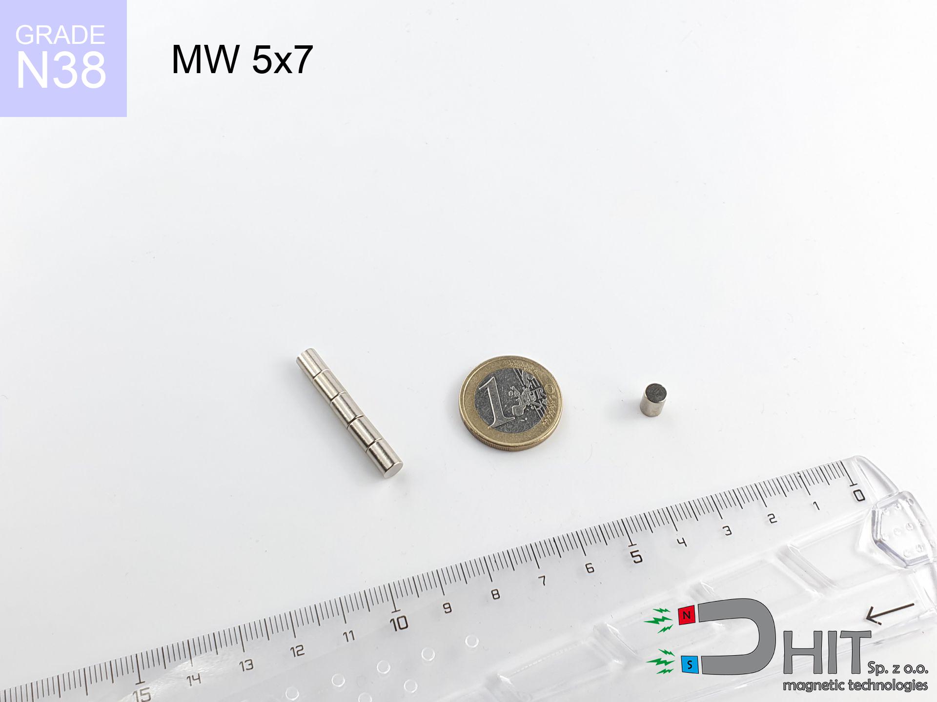
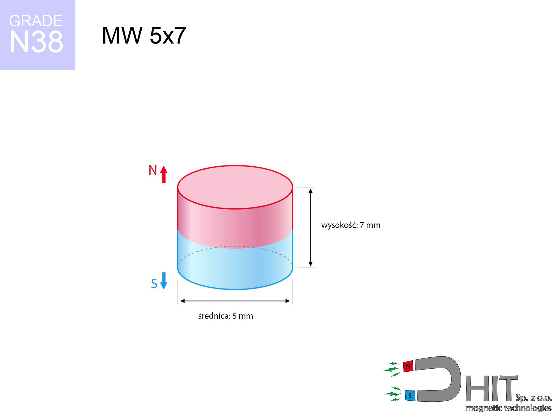
MW 5x7 / N38 - cylindrical magnet
cylindrical magnet
Catalog no 010090
GTIN/EAN: 5906301810896
Diameter Ø
5 mm [±0,1 mm]
Height
7 mm [±0,1 mm]
Weight
1.03 g
Magnetization Direction
↑ axial
Load capacity
0.67 kg / 6.60 N
Magnetic Induction
582.40 mT / 5824 Gs
Coating
[NiCuNi] Nickel
0.726 ZŁ with VAT / pcs + price for transport
0.590 ZŁ net + 23% VAT / pcs
bulk discounts:
Need more?
Pick up the phone and ask
+48 888 99 98 98
or get in touch via
our online form
through our site.
Parameters along with shape of magnets can be analyzed with our
magnetic calculator.
Same-day shipping for orders placed before 14:00.
Physical properties - MW 5x7 / N38 - cylindrical magnet
Specification / characteristics - MW 5x7 / N38 - cylindrical magnet
| properties | values |
|---|---|
| Cat. no. | 010090 |
| GTIN/EAN | 5906301810896 |
| Production/Distribution | Dhit sp. z o.o. |
| Country of origin | Poland / China / Germany |
| Customs code | 85059029 |
| Diameter Ø | 5 mm [±0,1 mm] |
| Height | 7 mm [±0,1 mm] |
| Weight | 1.03 g |
| Magnetization Direction | ↑ axial |
| Load capacity ~ ? | 0.67 kg / 6.60 N |
| Magnetic Induction ~ ? | 582.40 mT / 5824 Gs |
| Coating | [NiCuNi] Nickel |
| Manufacturing Tolerance | ±0.1 mm |
Magnetic properties of material N38
| properties | values | units |
|---|---|---|
| remenance Br [min. - max.] ? | 12.2-12.6 | kGs |
| remenance Br [min. - max.] ? | 1220-1260 | mT |
| coercivity bHc ? | 10.8-11.5 | kOe |
| coercivity bHc ? | 860-915 | kA/m |
| actual internal force iHc | ≥ 12 | kOe |
| actual internal force iHc | ≥ 955 | kA/m |
| energy density [min. - max.] ? | 36-38 | BH max MGOe |
| energy density [min. - max.] ? | 287-303 | BH max KJ/m |
| max. temperature ? | ≤ 80 | °C |
Physical properties of sintered neodymium magnets Nd2Fe14B at 20°C
| properties | values | units |
|---|---|---|
| Vickers hardness | ≥550 | Hv |
| Density | ≥7.4 | g/cm3 |
| Curie Temperature TC | 312 - 380 | °C |
| Curie Temperature TF | 593 - 716 | °F |
| Specific resistance | 150 | μΩ⋅cm |
| Bending strength | 250 | MPa |
| Compressive strength | 1000~1100 | MPa |
| Thermal expansion parallel (∥) to orientation (M) | (3-4) x 10-6 | °C-1 |
| Thermal expansion perpendicular (⊥) to orientation (M) | -(1-3) x 10-6 | °C-1 |
| Young's modulus | 1.7 x 10⁴ | kg/mm² |
Engineering modeling of the magnet - technical parameters
Presented information constitute the direct effect of a physical analysis. Results are based on algorithms for the material Nd2Fe14B. Actual conditions may differ. Please consider these data as a reference point for designers.
Table 1: Static force (pull vs distance) - characteristics
MW 5x7 / N38
| Distance (mm) | Induction (Gauss) / mT | Pull Force (kg/lbs/g/N) | Risk Status |
|---|---|---|---|
| 0 mm |
5815 Gs
581.5 mT
|
0.67 kg / 1.48 lbs
670.0 g / 6.6 N
|
low risk |
| 1 mm |
3615 Gs
361.5 mT
|
0.26 kg / 0.57 lbs
259.0 g / 2.5 N
|
low risk |
| 2 mm |
2101 Gs
210.1 mT
|
0.09 kg / 0.19 lbs
87.4 g / 0.9 N
|
low risk |
| 3 mm |
1252 Gs
125.2 mT
|
0.03 kg / 0.07 lbs
31.1 g / 0.3 N
|
low risk |
| 5 mm |
524 Gs
52.4 mT
|
0.01 kg / 0.01 lbs
5.4 g / 0.1 N
|
low risk |
| 10 mm |
119 Gs
11.9 mT
|
0.00 kg / 0.00 lbs
0.3 g / 0.0 N
|
low risk |
| 15 mm |
45 Gs
4.5 mT
|
0.00 kg / 0.00 lbs
0.0 g / 0.0 N
|
low risk |
| 20 mm |
21 Gs
2.1 mT
|
0.00 kg / 0.00 lbs
0.0 g / 0.0 N
|
low risk |
| 30 mm |
7 Gs
0.7 mT
|
0.00 kg / 0.00 lbs
0.0 g / 0.0 N
|
low risk |
| 50 mm |
2 Gs
0.2 mT
|
0.00 kg / 0.00 lbs
0.0 g / 0.0 N
|
low risk |
Table 2: Vertical load (wall)
MW 5x7 / N38
| Distance (mm) | Friction coefficient | Pull Force (kg/lbs/g/N) |
|---|---|---|
| 0 mm | Stal (~0.2) |
0.13 kg / 0.30 lbs
134.0 g / 1.3 N
|
| 1 mm | Stal (~0.2) |
0.05 kg / 0.11 lbs
52.0 g / 0.5 N
|
| 2 mm | Stal (~0.2) |
0.02 kg / 0.04 lbs
18.0 g / 0.2 N
|
| 3 mm | Stal (~0.2) |
0.01 kg / 0.01 lbs
6.0 g / 0.1 N
|
| 5 mm | Stal (~0.2) |
0.00 kg / 0.00 lbs
2.0 g / 0.0 N
|
| 10 mm | Stal (~0.2) |
0.00 kg / 0.00 lbs
0.0 g / 0.0 N
|
| 15 mm | Stal (~0.2) |
0.00 kg / 0.00 lbs
0.0 g / 0.0 N
|
| 20 mm | Stal (~0.2) |
0.00 kg / 0.00 lbs
0.0 g / 0.0 N
|
| 30 mm | Stal (~0.2) |
0.00 kg / 0.00 lbs
0.0 g / 0.0 N
|
| 50 mm | Stal (~0.2) |
0.00 kg / 0.00 lbs
0.0 g / 0.0 N
|
Table 3: Wall mounting (shearing) - behavior on slippery surfaces
MW 5x7 / N38
| Surface type | Friction coefficient / % Mocy | Max load (kg/lbs/g/N) |
|---|---|---|
| Raw steel |
µ = 0.3
30% Nominalnej Siły
|
0.20 kg / 0.44 lbs
201.0 g / 2.0 N
|
| Painted steel (standard) |
µ = 0.2
20% Nominalnej Siły
|
0.13 kg / 0.30 lbs
134.0 g / 1.3 N
|
| Oily/slippery steel |
µ = 0.1
10% Nominalnej Siły
|
0.07 kg / 0.15 lbs
67.0 g / 0.7 N
|
| Magnet with anti-slip rubber |
µ = 0.5
50% Nominalnej Siły
|
0.34 kg / 0.74 lbs
335.0 g / 3.3 N
|
Table 4: Material efficiency (saturation) - sheet metal selection
MW 5x7 / N38
| Steel thickness (mm) | % power | Real pull force (kg/lbs/g/N) |
|---|---|---|
| 0.5 mm |
|
0.07 kg / 0.15 lbs
67.0 g / 0.7 N
|
| 1 mm |
|
0.17 kg / 0.37 lbs
167.5 g / 1.6 N
|
| 2 mm |
|
0.34 kg / 0.74 lbs
335.0 g / 3.3 N
|
| 3 mm |
|
0.50 kg / 1.11 lbs
502.5 g / 4.9 N
|
| 5 mm |
|
0.67 kg / 1.48 lbs
670.0 g / 6.6 N
|
| 10 mm |
|
0.67 kg / 1.48 lbs
670.0 g / 6.6 N
|
| 11 mm |
|
0.67 kg / 1.48 lbs
670.0 g / 6.6 N
|
| 12 mm |
|
0.67 kg / 1.48 lbs
670.0 g / 6.6 N
|
Table 5: Working in heat (stability) - resistance threshold
MW 5x7 / N38
| Ambient temp. (°C) | Power loss | Remaining pull (kg/lbs/g/N) | Status |
|---|---|---|---|
| 20 °C | 0.0% |
0.67 kg / 1.48 lbs
670.0 g / 6.6 N
|
OK |
| 40 °C | -2.2% |
0.66 kg / 1.44 lbs
655.3 g / 6.4 N
|
OK |
| 60 °C | -4.4% |
0.64 kg / 1.41 lbs
640.5 g / 6.3 N
|
OK |
| 80 °C | -6.6% |
0.63 kg / 1.38 lbs
625.8 g / 6.1 N
|
|
| 100 °C | -28.8% |
0.48 kg / 1.05 lbs
477.0 g / 4.7 N
|
Table 6: Magnet-Magnet interaction (repulsion) - forces in the system
MW 5x7 / N38
| Gap (mm) | Attraction (kg/lbs) (N-S) | Lateral Force (kg/lbs/g/N) | Repulsion (kg/lbs) (N-N) |
|---|---|---|---|
| 0 mm |
4.09 kg / 9.02 lbs
6 079 Gs
|
0.61 kg / 1.35 lbs
614 g / 6.0 N
|
N/A |
| 1 mm |
2.64 kg / 5.81 lbs
9 332 Gs
|
0.40 kg / 0.87 lbs
395 g / 3.9 N
|
2.37 kg / 5.23 lbs
~0 Gs
|
| 2 mm |
1.58 kg / 3.49 lbs
7 230 Gs
|
0.24 kg / 0.52 lbs
237 g / 2.3 N
|
1.42 kg / 3.14 lbs
~0 Gs
|
| 3 mm |
0.92 kg / 2.03 lbs
5 516 Gs
|
0.14 kg / 0.30 lbs
138 g / 1.4 N
|
0.83 kg / 1.83 lbs
~0 Gs
|
| 5 mm |
0.31 kg / 0.69 lbs
3 224 Gs
|
0.05 kg / 0.10 lbs
47 g / 0.5 N
|
0.28 kg / 0.62 lbs
~0 Gs
|
| 10 mm |
0.03 kg / 0.07 lbs
1 048 Gs
|
0.00 kg / 0.01 lbs
5 g / 0.0 N
|
0.03 kg / 0.07 lbs
~0 Gs
|
| 20 mm |
0.00 kg / 0.00 lbs
238 Gs
|
0.00 kg / 0.00 lbs
0 g / 0.0 N
|
0.00 kg / 0.00 lbs
~0 Gs
|
| 50 mm |
0.00 kg / 0.00 lbs
24 Gs
|
0.00 kg / 0.00 lbs
0 g / 0.0 N
|
0.00 kg / 0.00 lbs
~0 Gs
|
| 60 mm |
0.00 kg / 0.00 lbs
15 Gs
|
0.00 kg / 0.00 lbs
0 g / 0.0 N
|
0.00 kg / 0.00 lbs
~0 Gs
|
| 70 mm |
0.00 kg / 0.00 lbs
10 Gs
|
0.00 kg / 0.00 lbs
0 g / 0.0 N
|
0.00 kg / 0.00 lbs
~0 Gs
|
| 80 mm |
0.00 kg / 0.00 lbs
7 Gs
|
0.00 kg / 0.00 lbs
0 g / 0.0 N
|
0.00 kg / 0.00 lbs
~0 Gs
|
| 90 mm |
0.00 kg / 0.00 lbs
5 Gs
|
0.00 kg / 0.00 lbs
0 g / 0.0 N
|
0.00 kg / 0.00 lbs
~0 Gs
|
| 100 mm |
0.00 kg / 0.00 lbs
4 Gs
|
0.00 kg / 0.00 lbs
0 g / 0.0 N
|
0.00 kg / 0.00 lbs
~0 Gs
|
Table 7: Hazards (implants) - precautionary measures
MW 5x7 / N38
| Object / Device | Limit (Gauss) / mT | Safe distance |
|---|---|---|
| Pacemaker | 5 Gs (0.5 mT) | 3.5 cm |
| Hearing aid | 10 Gs (1.0 mT) | 3.0 cm |
| Timepiece | 20 Gs (2.0 mT) | 2.5 cm |
| Mobile device | 40 Gs (4.0 mT) | 2.0 cm |
| Remote | 50 Gs (5.0 mT) | 1.5 cm |
| Payment card | 400 Gs (40.0 mT) | 1.0 cm |
| HDD hard drive | 600 Gs (60.0 mT) | 0.5 cm |
Table 8: Collisions (kinetic energy) - collision effects
MW 5x7 / N38
| Start from (mm) | Speed (km/h) | Energy (J) | Predicted outcome |
|---|---|---|---|
| 10 mm |
25.73 km/h
(7.15 m/s)
|
0.03 J | |
| 30 mm |
44.55 km/h
(12.38 m/s)
|
0.08 J | |
| 50 mm |
57.52 km/h
(15.98 m/s)
|
0.13 J | |
| 100 mm |
81.34 km/h
(22.59 m/s)
|
0.26 J |
Table 9: Corrosion resistance
MW 5x7 / N38
| Technical parameter | Value / Description |
|---|---|
| Coating type | [NiCuNi] Nickel |
| Layer structure | Nickel - Copper - Nickel |
| Layer thickness | 10-20 µm |
| Salt spray test (SST) ? | 24 h |
| Recommended environment | Indoors only (dry) |
Table 10: Electrical data (Flux)
MW 5x7 / N38
| Parameter | Value | SI Unit / Description |
|---|---|---|
| Magnetic Flux | 1 219 Mx | 12.2 µWb |
| Pc Coefficient | 1.05 | High (Stable) |
Table 11: Physics of underwater searching
MW 5x7 / N38
| Environment | Effective steel pull | Effect |
|---|---|---|
| Air (land) | 0.67 kg | Standard |
| Water (riverbed) |
0.77 kg
(+0.10 kg buoyancy gain)
|
+14.5% |
1. Shear force
*Caution: On a vertical surface, the magnet holds only ~20% of its max power.
2. Steel saturation
*Thin steel (e.g. 0.5mm PC case) drastically limits the holding force.
3. Power loss vs temp
*For standard magnets, the max working temp is 80°C.
4. Demagnetization curve and operating point (B-H)
chart generated for the permeance coefficient Pc (Permeance Coefficient) = 1.05
This simulation demonstrates the magnetic stability of the selected magnet under specific geometric conditions. The solid red line represents the demagnetization curve (material potential), while the dashed blue line is the load line based on the magnet's geometry. The Pc (Permeance Coefficient), also known as the load line slope, is a dimensionless value that describes the relationship between the magnet's shape and its magnetic stability. The intersection of these two lines (the black dot) is the operating point — it determines the actual magnetic flux density generated by the magnet in this specific configuration. A higher Pc value means the magnet is more 'slender' (tall relative to its area), resulting in a higher operating point and better resistance to irreversible demagnetization caused by external fields or temperature. A value of 0.42 is relatively low (typical for flat magnets), meaning the operating point is closer to the 'knee' of the curve — caution is advised when operating at temperatures near the maximum limit to avoid strength loss.
Material specification
| iron (Fe) | 64% – 68% |
| neodymium (Nd) | 29% – 32% |
| boron (B) | 1.1% – 1.2% |
| dysprosium (Dy) | 0.5% – 2.0% |
| coating (Ni-Cu-Ni) | < 0.05% |
Environmental data
| recyclability (EoL) | 100% |
| recycled raw materials | ~10% (pre-cons) |
| carbon footprint | low / zredukowany |
| waste code (EWC) | 16 02 16 |
View more proposals


![UMP 94x28 [3xM10] GW F300 GOLD Lina / N38 - search holder](https://cdn3.dhit.pl/graphics/products/ump-94x28-m10-gw-f300-+lina-kac.jpg "UMP 94x28 [3xM10] GW F300 GOLD Lina / N38 - search holder")
Pros and cons of rare earth magnets.
Advantages
- They have constant strength, and over nearly ten years their attraction force decreases symbolically – ~1% (in testing),
- They do not lose their magnetic properties even under external field action,
- Thanks to the glossy finish, the surface of nickel, gold, or silver-plated gives an clean appearance,
- Magnets have extremely high magnetic induction on the outer layer,
- Due to their durability and thermal resistance, neodymium magnets are capable of operate (depending on the shape) even at high temperatures reaching 230°C or more...
- In view of the potential of accurate molding and customization to custom requirements, NdFeB magnets can be modeled in a wide range of forms and dimensions, which expands the range of possible applications,
- Huge importance in future technologies – they are utilized in magnetic memories, electric motors, diagnostic systems, also complex engineering applications.
- Compactness – despite small sizes they provide effective action, making them ideal for precision applications
Limitations
- Brittleness is one of their disadvantages. Upon strong impact they can break. We advise keeping them in a steel housing, which not only protects them against impacts but also increases their durability
- Neodymium magnets decrease their strength under the influence of heating. As soon as 80°C is exceeded, many of them start losing their power. Therefore, we recommend our special magnets marked [AH], which maintain stability even at temperatures up to 230°C
- When exposed to humidity, magnets usually rust. To use them in conditions outside, it is recommended to use protective magnets, such as those in rubber or plastics, which secure oxidation as well as corrosion.
- Limited ability of producing nuts in the magnet and complex shapes - recommended is a housing - mounting mechanism.
- Health risk related to microscopic parts of magnets pose a threat, if swallowed, which gains importance in the context of child health protection. Additionally, tiny parts of these devices can complicate diagnosis medical in case of swallowing.
- Due to complex production process, their price exceeds standard values,
Holding force characteristics
Magnetic strength at its maximum – what it depends on?
- using a sheet made of low-carbon steel, acting as a magnetic yoke
- whose transverse dimension reaches at least 10 mm
- characterized by lack of roughness
- without any insulating layer between the magnet and steel
- for force applied at a right angle (pull-off, not shear)
- at standard ambient temperature
Practical lifting capacity: influencing factors
- Distance – existence of foreign body (rust, dirt, air) interrupts the magnetic circuit, which lowers capacity rapidly (even by 50% at 0.5 mm).
- Force direction – remember that the magnet holds strongest perpendicularly. Under sliding down, the holding force drops drastically, often to levels of 20-30% of the maximum value.
- Steel thickness – too thin sheet does not close the flux, causing part of the power to be wasted to the other side.
- Steel grade – the best choice is high-permeability steel. Cast iron may generate lower lifting capacity.
- Plate texture – ground elements ensure maximum contact, which increases force. Uneven metal weaken the grip.
- Thermal conditions – neodymium magnets have a negative temperature coefficient. When it is hot they are weaker, and in frost gain strength (up to a certain limit).
Holding force was tested on a smooth steel plate of 20 mm thickness, when the force acted perpendicularly, in contrast under attempts to slide the magnet the holding force is lower. Additionally, even a small distance between the magnet and the plate decreases the holding force.
Safe handling of NdFeB magnets
Keep away from computers
Device Safety: Neodymium magnets can damage data carriers and sensitive devices (heart implants, medical aids, timepieces).
Medical interference
Life threat: Strong magnets can deactivate pacemakers and defibrillators. Stay away if you have medical devices.
Thermal limits
Standard neodymium magnets (grade N) lose magnetization when the temperature surpasses 80°C. This process is irreversible.
GPS Danger
Remember: neodymium magnets produce a field that confuses sensitive sensors. Keep a safe distance from your mobile, tablet, and GPS.
Do not drill into magnets
Machining of neodymium magnets carries a risk of fire hazard. Neodymium dust oxidizes rapidly with oxygen and is hard to extinguish.
Nickel allergy
Warning for allergy sufferers: The nickel-copper-nickel coating consists of nickel. If redness occurs, cease working with magnets and use protective gear.
Crushing risk
Large magnets can smash fingers in a fraction of a second. Under no circumstances place your hand betwixt two strong magnets.
Risk of cracking
Beware of splinters. Magnets can fracture upon uncontrolled impact, ejecting shards into the air. Eye protection is mandatory.
Do not give to children
Always store magnets out of reach of children. Ingestion danger is significant, and the effects of magnets clamping inside the body are very dangerous.
Safe operation
Be careful. Rare earth magnets attract from a long distance and snap with huge force, often quicker than you can react.
Tabela kosztu i czasu dostawy
Płatność przed wysyłką:

GLS kurier
Przesyłka będzie u Ciebie za 2-3 dni
14.99 ZŁ

InPost Paczkomaty 24/7
Przesyłka będzie u Ciebie za 1-2 dni
12.30 ZŁ
Płatność przy odbiorze (pobranie):
GLS kurier
Przesyłka będzie u Ciebie za 1-2 dni
23.00 ZŁ
Rate the product
Your rating