
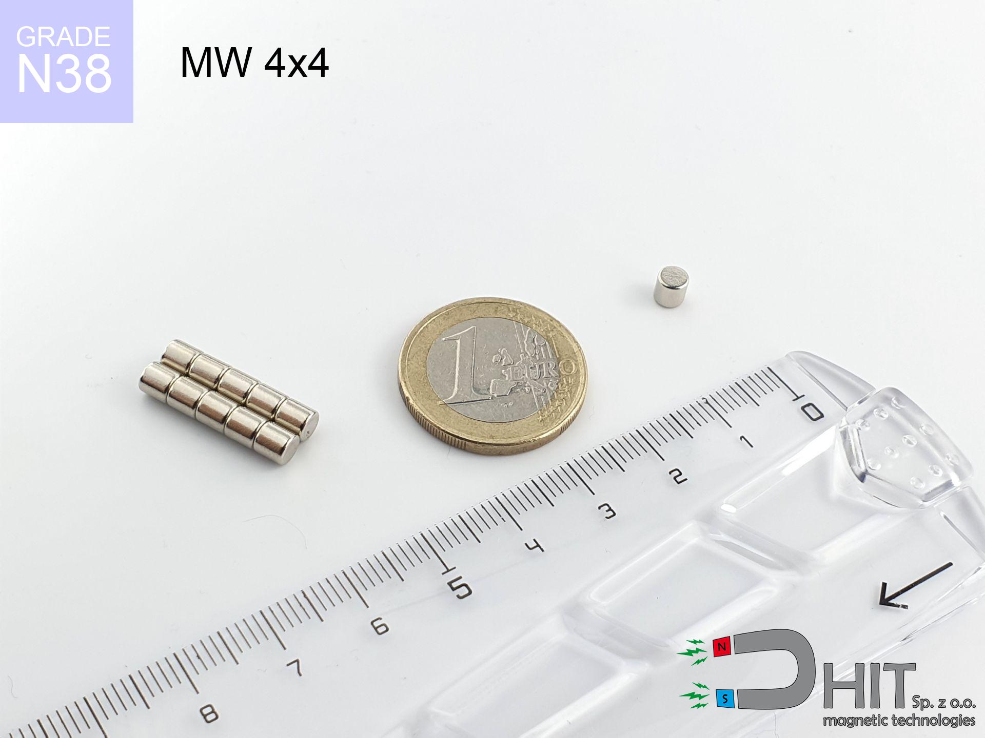
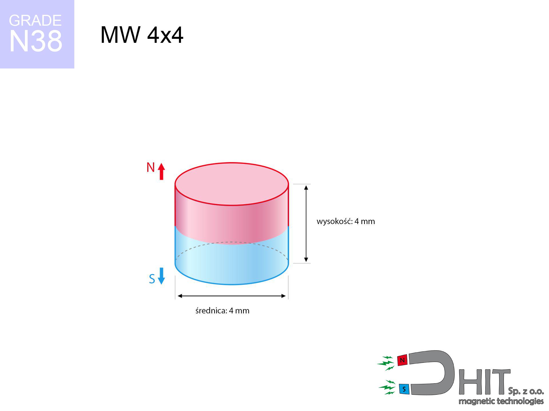
MW 4x4 / N38 - cylindrical magnet
cylindrical magnet
Catalog no 010076
GTIN/EAN: 5906301810759
Diameter Ø
4 mm [±0,1 mm]
Height
4 mm [±0,1 mm]
Weight
0.38 g
Magnetization Direction
↑ axial
Load capacity
0.51 kg / 4.96 N
Magnetic Induction
552.79 mT / 5528 Gs
Coating
[NiCuNi] Nickel
0.406 ZŁ with VAT / pcs + price for transport
0.330 ZŁ net + 23% VAT / pcs
bulk discounts:
Need more?Engineering report for this magnet
Full PDF analysis: pull and shear force, effect of distance, temperature and plate thickness, safety distances and the demagnetization curve.
Call us now
+48 888 99 98 98
alternatively drop us a message using
inquiry form
through our site.
Strength as well as structure of magnets can be estimated with our
modular calculator.
Order by 14:00 and we’ll ship today!
Technical data of the product - MW 4x4 / N38 - cylindrical magnet
Specification / characteristics - MW 4x4 / N38 - cylindrical magnet
| properties | values |
|---|---|
| Cat. no. | 010076 |
| GTIN/EAN | 5906301810759 |
| Production/Distribution | Dhit sp. z o.o. |
| Country of origin | Poland / China / Germany |
| Customs code | 85059029 |
| Diameter Ø | 4 mm [±0,1 mm] |
| Height | 4 mm [±0,1 mm] |
| Weight | 0.38 g |
| Magnetization Direction | ↑ axial |
| Load capacity ~ ? | 0.51 kg / 4.96 N |
| Magnetic Induction ~ ? | 552.79 mT / 5528 Gs |
| Coating | [NiCuNi] Nickel |
| Manufacturing Tolerance | ±0.1 mm |
Magnetic properties of material N38
| properties | values | units |
|---|---|---|
| remenance Br [min. - max.] ? | 12.2-12.6 | kGs |
| remenance Br [min. - max.] ? | 1220-1260 | mT |
| coercivity bHc ? | 10.8-11.5 | kOe |
| coercivity bHc ? | 860-915 | kA/m |
| actual internal force iHc | ≥ 12 | kOe |
| actual internal force iHc | ≥ 955 | kA/m |
| energy density [min. - max.] ? | 36-38 | BH max MGOe |
| energy density [min. - max.] ? | 287-303 | BH max KJ/m |
| max. temperature ? | ≤ 80 | °C |
Physical properties of sintered neodymium magnets Nd2Fe14B at 20°C
| properties | values | units |
|---|---|---|
| Vickers hardness | ≥550 | Hv |
| Density | ≥7.4 | g/cm3 |
| Curie Temperature TC | 312 - 380 | °C |
| Curie Temperature TF | 593 - 716 | °F |
| Specific resistance | 150 | μΩ⋅cm |
| Bending strength | 250 | MPa |
| Compressive strength | 1000~1100 | MPa |
| Thermal expansion parallel (∥) to orientation (M) | (3-4) x 10-6 | °C-1 |
| Thermal expansion perpendicular (⊥) to orientation (M) | -(1-3) x 10-6 | °C-1 |
| Young's modulus | 1.7 x 10⁴ | kg/mm² |
Physical analysis of the product - data
The following data are the direct effect of a physical calculation. Results were calculated on algorithms for the class Nd2Fe14B. Real-world parameters might slightly differ. Use these calculations as a preliminary roadmap when designing systems.
Table 1: Static force (pull vs gap) - interaction chart
MW 4x4 / N38
| Distance (mm) | Induction (Gauss) / mT | Pull Force (kg/lbs/g/N) | Risk Status |
|---|---|---|---|
| 0 mm |
5517 Gs
551.7 mT
|
0.51 kg / 1.12 LBS
510.0 g / 5.0 N
|
low risk |
| 1 mm |
2984 Gs
298.4 mT
|
0.15 kg / 0.33 LBS
149.2 g / 1.5 N
|
low risk |
| 2 mm |
1498 Gs
149.8 mT
|
0.04 kg / 0.08 LBS
37.6 g / 0.4 N
|
low risk |
| 3 mm |
803 Gs
80.3 mT
|
0.01 kg / 0.02 LBS
10.8 g / 0.1 N
|
low risk |
| 5 mm |
296 Gs
29.6 mT
|
0.00 kg / 0.00 LBS
1.5 g / 0.0 N
|
low risk |
| 10 mm |
58 Gs
5.8 mT
|
0.00 kg / 0.00 LBS
0.1 g / 0.0 N
|
low risk |
| 15 mm |
20 Gs
2.0 mT
|
0.00 kg / 0.00 LBS
0.0 g / 0.0 N
|
low risk |
| 20 mm |
9 Gs
0.9 mT
|
0.00 kg / 0.00 LBS
0.0 g / 0.0 N
|
low risk |
| 30 mm |
3 Gs
0.3 mT
|
0.00 kg / 0.00 LBS
0.0 g / 0.0 N
|
low risk |
| 50 mm |
1 Gs
0.1 mT
|
0.00 kg / 0.00 LBS
0.0 g / 0.0 N
|
low risk |
Table 2: Vertical capacity (wall)
MW 4x4 / N38
| Distance (mm) | Friction coefficient | Pull Force (kg/lbs/g/N) |
|---|---|---|
| 0 mm | Stal (~0.2) |
0.10 kg / 0.22 LBS
102.0 g / 1.0 N
|
| 1 mm | Stal (~0.2) |
0.03 kg / 0.07 LBS
30.0 g / 0.3 N
|
| 2 mm | Stal (~0.2) |
0.01 kg / 0.02 LBS
8.0 g / 0.1 N
|
| 3 mm | Stal (~0.2) |
0.00 kg / 0.00 LBS
2.0 g / 0.0 N
|
| 5 mm | Stal (~0.2) |
0.00 kg / 0.00 LBS
0.0 g / 0.0 N
|
| 10 mm | Stal (~0.2) |
0.00 kg / 0.00 LBS
0.0 g / 0.0 N
|
| 15 mm | Stal (~0.2) |
0.00 kg / 0.00 LBS
0.0 g / 0.0 N
|
| 20 mm | Stal (~0.2) |
0.00 kg / 0.00 LBS
0.0 g / 0.0 N
|
| 30 mm | Stal (~0.2) |
0.00 kg / 0.00 LBS
0.0 g / 0.0 N
|
| 50 mm | Stal (~0.2) |
0.00 kg / 0.00 LBS
0.0 g / 0.0 N
|
Table 3: Vertical assembly (shearing) - vertical pull
MW 4x4 / N38
| Surface type | Friction coefficient / % Mocy | Max load (kg/lbs/g/N) |
|---|---|---|
| Raw steel |
µ = 0.3
30% Nominalnej Siły
|
0.15 kg / 0.34 LBS
153.0 g / 1.5 N
|
| Painted steel (standard) |
µ = 0.2
20% Nominalnej Siły
|
0.10 kg / 0.22 LBS
102.0 g / 1.0 N
|
| Oily/slippery steel |
µ = 0.1
10% Nominalnej Siły
|
0.05 kg / 0.11 LBS
51.0 g / 0.5 N
|
| Magnet with anti-slip rubber |
µ = 0.5
50% Nominalnej Siły
|
0.26 kg / 0.56 LBS
255.0 g / 2.5 N
|
Table 4: Steel thickness (saturation) - power losses
MW 4x4 / N38
| Steel thickness (mm) | % power | Real pull force (kg/lbs/g/N) |
|---|---|---|
| 0.5 mm |
|
0.05 kg / 0.11 LBS
51.0 g / 0.5 N
|
| 1 mm |
|
0.13 kg / 0.28 LBS
127.5 g / 1.3 N
|
| 2 mm |
|
0.26 kg / 0.56 LBS
255.0 g / 2.5 N
|
| 3 mm |
|
0.38 kg / 0.84 LBS
382.5 g / 3.8 N
|
| 5 mm |
|
0.51 kg / 1.12 LBS
510.0 g / 5.0 N
|
| 10 mm |
|
0.51 kg / 1.12 LBS
510.0 g / 5.0 N
|
| 11 mm |
|
0.51 kg / 1.12 LBS
510.0 g / 5.0 N
|
| 12 mm |
|
0.51 kg / 1.12 LBS
510.0 g / 5.0 N
|
Table 5: Thermal stability (material behavior) - thermal limit
MW 4x4 / N38
| Ambient temp. (°C) | Power loss | Remaining pull (kg/lbs/g/N) | Status |
|---|---|---|---|
| 20 °C | 0.0% |
0.51 kg / 1.12 LBS
510.0 g / 5.0 N
|
OK |
| 40 °C | -2.2% |
0.50 kg / 1.10 LBS
498.8 g / 4.9 N
|
OK |
| 60 °C | -4.4% |
0.49 kg / 1.07 LBS
487.6 g / 4.8 N
|
OK |
| 80 °C | -6.6% |
0.48 kg / 1.05 LBS
476.3 g / 4.7 N
|
|
| 100 °C | -28.8% |
0.36 kg / 0.80 LBS
363.1 g / 3.6 N
|
Table 6: Two magnets (attraction) - field range
MW 4x4 / N38
| Gap (mm) | Attraction (kg/lbs) (N-S) | Shear Force (kg/lbs/g/N) | Repulsion (kg/lbs) (N-N) |
|---|---|---|---|
| 0 mm |
2.36 kg / 5.20 LBS
5 984 Gs
|
0.35 kg / 0.78 LBS
354 g / 3.5 N
|
N/A |
| 1 mm |
1.34 kg / 2.96 LBS
8 324 Gs
|
0.20 kg / 0.44 LBS
201 g / 2.0 N
|
1.21 kg / 2.66 LBS
~0 Gs
|
| 2 mm |
0.69 kg / 1.52 LBS
5 968 Gs
|
0.10 kg / 0.23 LBS
103 g / 1.0 N
|
0.62 kg / 1.37 LBS
~0 Gs
|
| 3 mm |
0.34 kg / 0.76 LBS
4 213 Gs
|
0.05 kg / 0.11 LBS
52 g / 0.5 N
|
0.31 kg / 0.68 LBS
~0 Gs
|
| 5 mm |
0.09 kg / 0.20 LBS
2 169 Gs
|
0.01 kg / 0.03 LBS
14 g / 0.1 N
|
0.08 kg / 0.18 LBS
~0 Gs
|
| 10 mm |
0.01 kg / 0.01 LBS
592 Gs
|
0.00 kg / 0.00 LBS
1 g / 0.0 N
|
0.00 kg / 0.00 LBS
~0 Gs
|
| 20 mm |
0.00 kg / 0.00 LBS
116 Gs
|
0.00 kg / 0.00 LBS
0 g / 0.0 N
|
0.00 kg / 0.00 LBS
~0 Gs
|
| 50 mm |
0.00 kg / 0.00 LBS
10 Gs
|
0.00 kg / 0.00 LBS
0 g / 0.0 N
|
0.00 kg / 0.00 LBS
~0 Gs
|
| 60 mm |
0.00 kg / 0.00 LBS
6 Gs
|
0.00 kg / 0.00 LBS
0 g / 0.0 N
|
0.00 kg / 0.00 LBS
~0 Gs
|
| 70 mm |
0.00 kg / 0.00 LBS
4 Gs
|
0.00 kg / 0.00 LBS
0 g / 0.0 N
|
0.00 kg / 0.00 LBS
~0 Gs
|
| 80 mm |
0.00 kg / 0.00 LBS
3 Gs
|
0.00 kg / 0.00 LBS
0 g / 0.0 N
|
0.00 kg / 0.00 LBS
~0 Gs
|
| 90 mm |
0.00 kg / 0.00 LBS
2 Gs
|
0.00 kg / 0.00 LBS
0 g / 0.0 N
|
0.00 kg / 0.00 LBS
~0 Gs
|
| 100 mm |
0.00 kg / 0.00 LBS
1 Gs
|
0.00 kg / 0.00 LBS
0 g / 0.0 N
|
0.00 kg / 0.00 LBS
~0 Gs
|
Table 7: Protective zones (implants) - warnings
MW 4x4 / N38
| Object / Device | Limit (Gauss) / mT | Safe distance |
|---|---|---|
| Pacemaker | 5 Gs (0.5 mT) | 3.0 cm |
| Hearing aid | 10 Gs (1.0 mT) | 2.0 cm |
| Timepiece | 20 Gs (2.0 mT) | 2.0 cm |
| Phone / Smartphone | 40 Gs (4.0 mT) | 1.5 cm |
| Remote | 50 Gs (5.0 mT) | 1.5 cm |
| Payment card | 400 Gs (40.0 mT) | 0.5 cm |
| HDD hard drive | 600 Gs (60.0 mT) | 0.5 cm |
Table 8: Collisions (cracking risk) - warning
MW 4x4 / N38
| Start from (mm) | Speed (km/h) | Energy (J) | Predicted outcome |
|---|---|---|---|
| 10 mm |
36.95 km/h
(10.26 m/s)
|
0.02 J | |
| 30 mm |
63.99 km/h
(17.78 m/s)
|
0.06 J | |
| 50 mm |
82.62 km/h
(22.95 m/s)
|
0.10 J | |
| 100 mm |
116.84 km/h
(32.45 m/s)
|
0.20 J |
Table 9: Corrosion resistance
MW 4x4 / N38
| Technical parameter | Value / Description |
|---|---|
| Coating type | [NiCuNi] Nickel |
| Layer structure | Nickel - Copper - Nickel |
| Layer thickness | 10-20 µm |
| Salt spray test (SST) ? | 24 h |
| Recommended environment | Indoors only (dry) |
Table 10: Electrical data (Flux)
MW 4x4 / N38
| Parameter | Value | SI Unit / Description |
|---|---|---|
| Magnetic Flux | 717 Mx | 7.2 µWb |
| Pc Coefficient | 0.89 | High (Stable) |
Table 11: Submerged application
MW 4x4 / N38
| Environment | Effective steel pull | Effect |
|---|---|---|
| Air (land) | 0.51 kg | Standard |
| Water (riverbed) |
0.58 kg
(+0.07 kg buoyancy gain)
|
+14.5% |
1. Sliding resistance
*Caution: On a vertical surface, the magnet holds merely ~20% of its nominal pull.
2. Steel thickness impact
*Thin metal sheet (e.g. computer case) severely weakens the holding force.
3. Power loss vs temp
*For N38 grade, the critical limit is 80°C.
4. Demagnetization curve and operating point (B-H)
chart generated for the permeance coefficient Pc (Permeance Coefficient) = 0.89
This simulation demonstrates the magnetic stability of the selected magnet under specific geometric conditions. The solid red line represents the demagnetization curve (material potential), while the dashed blue line is the load line based on the magnet's geometry. The Pc (Permeance Coefficient), also known as the load line slope, is a dimensionless value that describes the relationship between the magnet's shape and its magnetic stability. The intersection of these two lines (the black dot) is the operating point — it determines the actual magnetic flux density generated by the magnet in this specific configuration. A higher Pc value means the magnet is more 'slender' (tall relative to its area), resulting in a higher operating point and better resistance to irreversible demagnetization caused by external fields or temperature. A value of 0.42 is relatively low (typical for flat magnets), meaning the operating point is closer to the 'knee' of the curve — caution is advised when operating at temperatures near the maximum limit to avoid strength loss.
Material specification
| iron (Fe) | 64% – 68% |
| neodymium (Nd) | 29% – 32% |
| boron (B) | 1.1% – 1.2% |
| dysprosium (Dy) | 0.5% – 2.0% |
| coating (Ni-Cu-Ni) | < 0.05% |
Ecology and recycling (GPSR)
| recyclability (EoL) | 100% |
| recycled raw materials | ~10% (pre-cons) |
| carbon footprint | low / zredukowany |
| waste code (EWC) | 16 02 16 |
Check out more proposals


![BM 380x180x70 [4x M8] - magnetic beam](https://cdn3.dhit.pl/graphics/products/bm-380x180x70-4x-m8-wex.jpg "BM 380x180x70 [4x M8] - magnetic beam")
![SM 32x275 [2xM8] / N42 - magnetic separator](https://cdn3.dhit.pl/graphics/products/sm-32x275-2xm8-hac.jpg "SM 32x275 [2xM8] / N42 - magnetic separator")
Advantages and disadvantages of neodymium magnets.
Benefits
- They have constant strength, and over around 10 years their performance decreases symbolically – ~1% (in testing),
- They feature excellent resistance to magnetism drop due to external magnetic sources,
- The use of an metallic finish of noble metals (nickel, gold, silver) causes the element to have aesthetics,
- Neodymium magnets create maximum magnetic induction on a their surface, which ensures high operational effectiveness,
- Made from properly selected components, these magnets show impressive resistance to high heat, enabling them to function (depending on their form) at temperatures up to 230°C and above...
- Possibility of exact modeling and adjusting to defined requirements,
- Universal use in future technologies – they are used in HDD drives, electric motors, medical devices, and other advanced devices.
- Compactness – despite small sizes they offer powerful magnetic field, making them ideal for precision applications
Limitations
- At very strong impacts they can break, therefore we recommend placing them in steel cases. A metal housing provides additional protection against damage, as well as increases the magnet's durability.
- NdFeB magnets demagnetize when exposed to high temperatures. After reaching 80°C, many of them experience permanent drop of power (a factor is the shape and dimensions of the magnet). We offer magnets specially adapted to work at temperatures up to 230°C marked [AH], which are extremely resistant to heat
- Magnets exposed to a humid environment can rust. Therefore during using outdoors, we recommend using water-impermeable magnets made of rubber, plastic or other material protecting against moisture
- We suggest cover - magnetic holder, due to difficulties in realizing nuts inside the magnet and complicated forms.
- Health risk to health – tiny shards of magnets are risky, when accidentally swallowed, which gains importance in the aspect of protecting the youngest. It is also worth noting that small elements of these magnets are able to complicate diagnosis medical after entering the body.
- High unit price – neodymium magnets cost more than other types of magnets (e.g. ferrite), which can limit application in large quantities
Lifting parameters
Maximum holding power of the magnet – what it depends on?
- on a base made of mild steel, optimally conducting the magnetic field
- whose transverse dimension equals approx. 10 mm
- characterized by smoothness
- with total lack of distance (no impurities)
- during detachment in a direction perpendicular to the mounting surface
- at room temperature
Magnet lifting force in use – key factors
- Space between magnet and steel – every millimeter of separation (caused e.g. by veneer or dirt) significantly weakens the pulling force, often by half at just 0.5 mm.
- Angle of force application – highest force is reached only during perpendicular pulling. The force required to slide of the magnet along the plate is usually several times lower (approx. 1/5 of the lifting capacity).
- Element thickness – to utilize 100% power, the steel must be sufficiently thick. Paper-thin metal limits the attraction force (the magnet "punches through" it).
- Material type – ideal substrate is high-permeability steel. Stainless steels may attract less.
- Smoothness – ideal contact is obtained only on smooth steel. Rough texture create air cushions, reducing force.
- Temperature influence – hot environment weakens magnetic field. Exceeding the limit temperature can permanently damage the magnet.
Lifting capacity testing was performed on plates with a smooth surface of optimal thickness, under perpendicular forces, in contrast under shearing force the holding force is lower. Moreover, even a small distance between the magnet and the plate decreases the holding force.
H&S for magnets
Adults only
These products are not suitable for play. Accidental ingestion of several magnets may result in them pinching intestinal walls, which poses a severe health hazard and requires immediate surgery.
Danger to pacemakers
For implant holders: Powerful magnets affect electronics. Keep at least 30 cm distance or request help to work with the magnets.
Allergic reactions
Studies show that the nickel plating (the usual finish) is a potent allergen. For allergy sufferers, refrain from touching magnets with bare hands and opt for versions in plastic housing.
Electronic hazard
Do not bring magnets close to a wallet, laptop, or TV. The magnetic field can irreversibly ruin these devices and erase data from cards.
Fire risk
Fire hazard: Neodymium dust is highly flammable. Do not process magnets without safety gear as this may cause fire.
Crushing force
Pinching hazard: The attraction force is so immense that it can cause blood blisters, pinching, and broken bones. Protective gloves are recommended.
Do not overheat magnets
Regular neodymium magnets (N-type) lose power when the temperature surpasses 80°C. The loss of strength is permanent.
Magnets are brittle
NdFeB magnets are ceramic materials, which means they are prone to chipping. Impact of two magnets will cause them cracking into small pieces.
Respect the power
Before use, read the rules. Uncontrolled attraction can break the magnet or injure your hand. Be predictive.
Phone sensors
GPS units and smartphones are extremely susceptible to magnetic fields. Direct contact with a strong magnet can ruin the internal compass in your phone.
Tabela kosztu i czasu dostawy
Płatność przed wysyłką:

GLS kurier
Przesyłka będzie u Ciebie za 2-3 dni
14.99 ZŁ

InPost Paczkomaty 24/7
Przesyłka będzie u Ciebie za 1-2 dni
12.30 ZŁ
Płatność przy odbiorze (pobranie):
GLS kurier
Przesyłka będzie u Ciebie za 1-2 dni
23.00 ZŁ
Rate the product
Your rating