
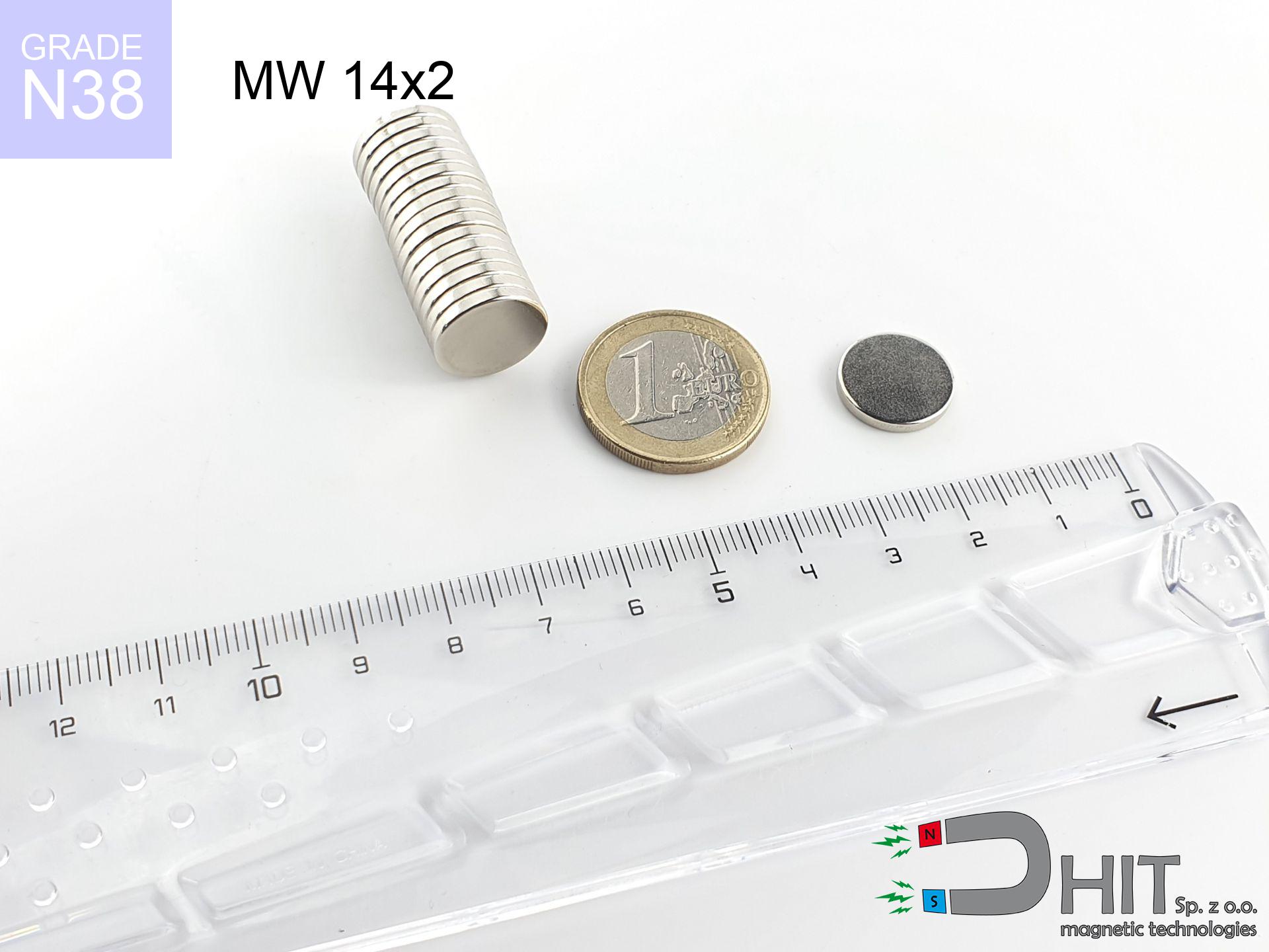
MW 14x2 / N38 - cylindrical magnet
cylindrical magnet
Catalog no 010024
GTIN/EAN: 5906301810230
Diameter Ø
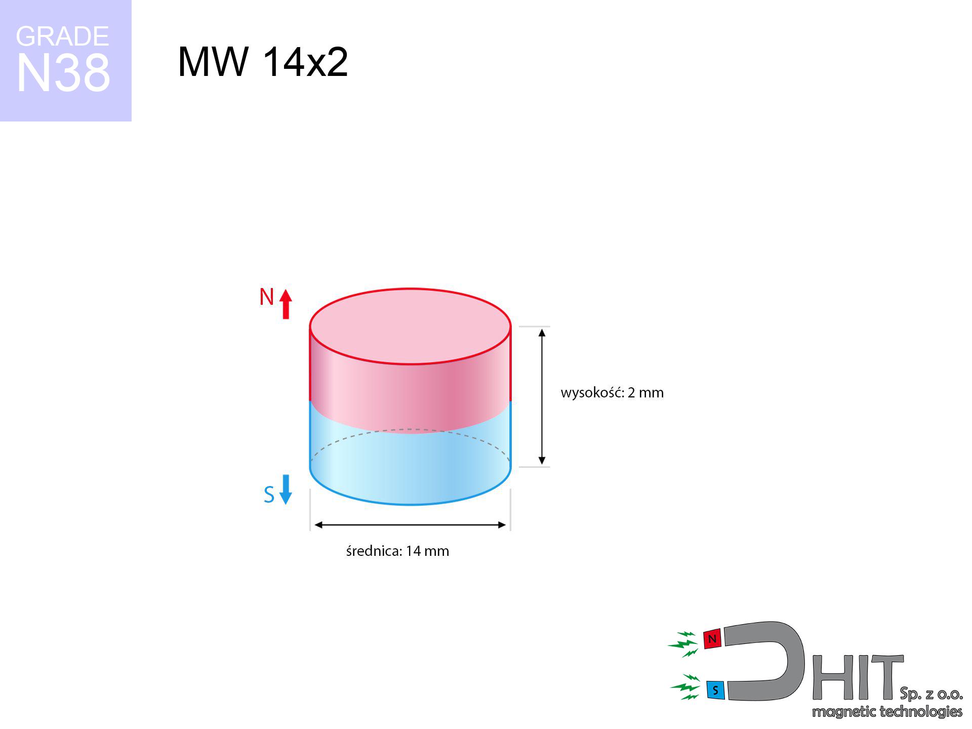
14 mm [±0,1 mm]
Height
2 mm [±0,1 mm]
Weight
2.31 g
Magnetization Direction
↑ axial
Load capacity
1.48 kg / 14.51 N
Magnetic Induction
170.27 mT / 1703 Gs
Coating
[NiCuNi] Nickel
0.898 ZŁ with VAT / pcs + price for transport
0.730 ZŁ net + 23% VAT / pcs
bulk discounts:
Need more?
Give us a call
+48 888 99 98 98
or contact us by means of
contact form
the contact section.
Strength and structure of magnets can be calculated using our
our magnetic calculator.
Order by 14:00 and we’ll ship today!
Product card - MW 14x2 / N38 - cylindrical magnet
Specification / characteristics - MW 14x2 / N38 - cylindrical magnet
| properties | values |
|---|---|
| Cat. no. | 010024 |
| GTIN/EAN | 5906301810230 |
| Production/Distribution | Dhit sp. z o.o. |
| Country of origin | Poland / China / Germany |
| Customs code | 85059029 |
| Diameter Ø | 14 mm [±0,1 mm] |
| Height | 2 mm [±0,1 mm] |
| Weight | 2.31 g |
| Magnetization Direction | ↑ axial |
| Load capacity ~ ? | 1.48 kg / 14.51 N |
| Magnetic Induction ~ ? | 170.27 mT / 1703 Gs |
| Coating | [NiCuNi] Nickel |
| Manufacturing Tolerance | ±0.1 mm |
Magnetic properties of material N38
| properties | values | units |
|---|---|---|
| remenance Br [min. - max.] ? | 12.2-12.6 | kGs |
| remenance Br [min. - max.] ? | 1220-1260 | mT |
| coercivity bHc ? | 10.8-11.5 | kOe |
| coercivity bHc ? | 860-915 | kA/m |
| actual internal force iHc | ≥ 12 | kOe |
| actual internal force iHc | ≥ 955 | kA/m |
| energy density [min. - max.] ? | 36-38 | BH max MGOe |
| energy density [min. - max.] ? | 287-303 | BH max KJ/m |
| max. temperature ? | ≤ 80 | °C |
Physical properties of sintered neodymium magnets Nd2Fe14B at 20°C
| properties | values | units |
|---|---|---|
| Vickers hardness | ≥550 | Hv |
| Density | ≥7.4 | g/cm3 |
| Curie Temperature TC | 312 - 380 | °C |
| Curie Temperature TF | 593 - 716 | °F |
| Specific resistance | 150 | μΩ⋅cm |
| Bending strength | 250 | MPa |
| Compressive strength | 1000~1100 | MPa |
| Thermal expansion parallel (∥) to orientation (M) | (3-4) x 10-6 | °C-1 |
| Thermal expansion perpendicular (⊥) to orientation (M) | -(1-3) x 10-6 | °C-1 |
| Young's modulus | 1.7 x 10⁴ | kg/mm² |
Technical modeling of the assembly - report
These data represent the result of a mathematical calculation. Values were calculated on models for the class Nd2Fe14B. Actual performance might slightly differ from theoretical values. Please consider these data as a preliminary roadmap during assembly planning.
Table 1: Static force (pull vs distance) - power drop
MW 14x2 / N38
| Distance (mm) | Induction (Gauss) / mT | Pull Force (kg/lbs/g/N) | Risk Status |
|---|---|---|---|
| 0 mm |
1702 Gs
170.2 mT
|
1.48 kg / 3.26 lbs
1480.0 g / 14.5 N
|
weak grip |
| 1 mm |
1565 Gs
156.5 mT
|
1.25 kg / 2.76 lbs
1251.7 g / 12.3 N
|
weak grip |
| 2 mm |
1373 Gs
137.3 mT
|
0.96 kg / 2.12 lbs
962.5 g / 9.4 N
|
weak grip |
| 3 mm |
1161 Gs
116.1 mT
|
0.69 kg / 1.52 lbs
688.9 g / 6.8 N
|
weak grip |
| 5 mm |
780 Gs
78.0 mT
|
0.31 kg / 0.69 lbs
311.0 g / 3.1 N
|
weak grip |
| 10 mm |
276 Gs
27.6 mT
|
0.04 kg / 0.09 lbs
39.0 g / 0.4 N
|
weak grip |
| 15 mm |
115 Gs
11.5 mT
|
0.01 kg / 0.01 lbs
6.7 g / 0.1 N
|
weak grip |
| 20 mm |
56 Gs
5.6 mT
|
0.00 kg / 0.00 lbs
1.6 g / 0.0 N
|
weak grip |
| 30 mm |
19 Gs
1.9 mT
|
0.00 kg / 0.00 lbs
0.2 g / 0.0 N
|
weak grip |
| 50 mm |
4 Gs
0.4 mT
|
0.00 kg / 0.00 lbs
0.0 g / 0.0 N
|
weak grip |
Table 2: Slippage capacity (vertical surface)
MW 14x2 / N38
| Distance (mm) | Friction coefficient | Pull Force (kg/lbs/g/N) |
|---|---|---|
| 0 mm | Stal (~0.2) |
0.30 kg / 0.65 lbs
296.0 g / 2.9 N
|
| 1 mm | Stal (~0.2) |
0.25 kg / 0.55 lbs
250.0 g / 2.5 N
|
| 2 mm | Stal (~0.2) |
0.19 kg / 0.42 lbs
192.0 g / 1.9 N
|
| 3 mm | Stal (~0.2) |
0.14 kg / 0.30 lbs
138.0 g / 1.4 N
|
| 5 mm | Stal (~0.2) |
0.06 kg / 0.14 lbs
62.0 g / 0.6 N
|
| 10 mm | Stal (~0.2) |
0.01 kg / 0.02 lbs
8.0 g / 0.1 N
|
| 15 mm | Stal (~0.2) |
0.00 kg / 0.00 lbs
2.0 g / 0.0 N
|
| 20 mm | Stal (~0.2) |
0.00 kg / 0.00 lbs
0.0 g / 0.0 N
|
| 30 mm | Stal (~0.2) |
0.00 kg / 0.00 lbs
0.0 g / 0.0 N
|
| 50 mm | Stal (~0.2) |
0.00 kg / 0.00 lbs
0.0 g / 0.0 N
|
Table 3: Wall mounting (shearing) - behavior on slippery surfaces
MW 14x2 / N38
| Surface type | Friction coefficient / % Mocy | Max load (kg/lbs/g/N) |
|---|---|---|
| Raw steel |
µ = 0.3
30% Nominalnej Siły
|
0.44 kg / 0.98 lbs
444.0 g / 4.4 N
|
| Painted steel (standard) |
µ = 0.2
20% Nominalnej Siły
|
0.30 kg / 0.65 lbs
296.0 g / 2.9 N
|
| Oily/slippery steel |
µ = 0.1
10% Nominalnej Siły
|
0.15 kg / 0.33 lbs
148.0 g / 1.5 N
|
| Magnet with anti-slip rubber |
µ = 0.5
50% Nominalnej Siły
|
0.74 kg / 1.63 lbs
740.0 g / 7.3 N
|
Table 4: Steel thickness (saturation) - power losses
MW 14x2 / N38
| Steel thickness (mm) | % power | Real pull force (kg/lbs/g/N) |
|---|---|---|
| 0.5 mm |
|
0.15 kg / 0.33 lbs
148.0 g / 1.5 N
|
| 1 mm |
|
0.37 kg / 0.82 lbs
370.0 g / 3.6 N
|
| 2 mm |
|
0.74 kg / 1.63 lbs
740.0 g / 7.3 N
|
| 3 mm |
|
1.11 kg / 2.45 lbs
1110.0 g / 10.9 N
|
| 5 mm |
|
1.48 kg / 3.26 lbs
1480.0 g / 14.5 N
|
| 10 mm |
|
1.48 kg / 3.26 lbs
1480.0 g / 14.5 N
|
| 11 mm |
|
1.48 kg / 3.26 lbs
1480.0 g / 14.5 N
|
| 12 mm |
|
1.48 kg / 3.26 lbs
1480.0 g / 14.5 N
|
Table 5: Thermal resistance (material behavior) - power drop
MW 14x2 / N38
| Ambient temp. (°C) | Power loss | Remaining pull (kg/lbs/g/N) | Status |
|---|---|---|---|
| 20 °C | 0.0% |
1.48 kg / 3.26 lbs
1480.0 g / 14.5 N
|
OK |
| 40 °C | -2.2% |
1.45 kg / 3.19 lbs
1447.4 g / 14.2 N
|
OK |
| 60 °C | -4.4% |
1.41 kg / 3.12 lbs
1414.9 g / 13.9 N
|
|
| 80 °C | -6.6% |
1.38 kg / 3.05 lbs
1382.3 g / 13.6 N
|
|
| 100 °C | -28.8% |
1.05 kg / 2.32 lbs
1053.8 g / 10.3 N
|
Table 6: Magnet-Magnet interaction (attraction) - forces in the system
MW 14x2 / N38
| Gap (mm) | Attraction (kg/lbs) (N-S) | Lateral Force (kg/lbs/g/N) | Repulsion (kg/lbs) (N-N) |
|---|---|---|---|
| 0 mm |
2.75 kg / 6.06 lbs
3 073 Gs
|
0.41 kg / 0.91 lbs
413 g / 4.0 N
|
N/A |
| 1 mm |
2.56 kg / 5.65 lbs
3 287 Gs
|
0.38 kg / 0.85 lbs
385 g / 3.8 N
|
2.31 kg / 5.09 lbs
~0 Gs
|
| 2 mm |
2.33 kg / 5.13 lbs
3 131 Gs
|
0.35 kg / 0.77 lbs
349 g / 3.4 N
|
2.09 kg / 4.61 lbs
~0 Gs
|
| 3 mm |
2.06 kg / 4.54 lbs
2 947 Gs
|
0.31 kg / 0.68 lbs
309 g / 3.0 N
|
1.85 kg / 4.09 lbs
~0 Gs
|
| 5 mm |
1.52 kg / 3.36 lbs
2 535 Gs
|
0.23 kg / 0.50 lbs
229 g / 2.2 N
|
1.37 kg / 3.02 lbs
~0 Gs
|
| 10 mm |
0.58 kg / 1.27 lbs
1 561 Gs
|
0.09 kg / 0.19 lbs
87 g / 0.9 N
|
0.52 kg / 1.15 lbs
~0 Gs
|
| 20 mm |
0.07 kg / 0.16 lbs
552 Gs
|
0.01 kg / 0.02 lbs
11 g / 0.1 N
|
0.07 kg / 0.14 lbs
~0 Gs
|
| 50 mm |
0.00 kg / 0.00 lbs
62 Gs
|
0.00 kg / 0.00 lbs
0 g / 0.0 N
|
0.00 kg / 0.00 lbs
~0 Gs
|
| 60 mm |
0.00 kg / 0.00 lbs
38 Gs
|
0.00 kg / 0.00 lbs
0 g / 0.0 N
|
0.00 kg / 0.00 lbs
~0 Gs
|
| 70 mm |
0.00 kg / 0.00 lbs
25 Gs
|
0.00 kg / 0.00 lbs
0 g / 0.0 N
|
0.00 kg / 0.00 lbs
~0 Gs
|
| 80 mm |
0.00 kg / 0.00 lbs
17 Gs
|
0.00 kg / 0.00 lbs
0 g / 0.0 N
|
0.00 kg / 0.00 lbs
~0 Gs
|
| 90 mm |
0.00 kg / 0.00 lbs
12 Gs
|
0.00 kg / 0.00 lbs
0 g / 0.0 N
|
0.00 kg / 0.00 lbs
~0 Gs
|
| 100 mm |
0.00 kg / 0.00 lbs
9 Gs
|
0.00 kg / 0.00 lbs
0 g / 0.0 N
|
0.00 kg / 0.00 lbs
~0 Gs
|
Table 7: Hazards (implants) - precautionary measures
MW 14x2 / N38
| Object / Device | Limit (Gauss) / mT | Safe distance |
|---|---|---|
| Pacemaker | 5 Gs (0.5 mT) | 5.0 cm |
| Hearing aid | 10 Gs (1.0 mT) | 4.0 cm |
| Timepiece | 20 Gs (2.0 mT) | 3.0 cm |
| Phone / Smartphone | 40 Gs (4.0 mT) | 2.5 cm |
| Car key | 50 Gs (5.0 mT) | 2.5 cm |
| Payment card | 400 Gs (40.0 mT) | 1.0 cm |
| HDD hard drive | 600 Gs (60.0 mT) | 1.0 cm |
Table 8: Dynamics (cracking risk) - collision effects
MW 14x2 / N38
| Start from (mm) | Speed (km/h) | Energy (J) | Predicted outcome |
|---|---|---|---|
| 10 mm |
25.94 km/h
(7.21 m/s)
|
0.06 J | |
| 30 mm |
44.22 km/h
(12.28 m/s)
|
0.17 J | |
| 50 mm |
57.08 km/h
(15.86 m/s)
|
0.29 J | |
| 100 mm |
80.72 km/h
(22.42 m/s)
|
0.58 J |
Table 9: Coating parameters (durability)
MW 14x2 / N38
| Technical parameter | Value / Description |
|---|---|
| Coating type | [NiCuNi] Nickel |
| Layer structure | Nickel - Copper - Nickel |
| Layer thickness | 10-20 µm |
| Salt spray test (SST) ? | 24 h |
| Recommended environment | Indoors only (dry) |
Table 10: Electrical data (Flux)
MW 14x2 / N38
| Parameter | Value | SI Unit / Description |
|---|---|---|
| Magnetic Flux | 3 247 Mx | 32.5 µWb |
| Pc Coefficient | 0.22 | Low (Flat) |
Table 11: Underwater work (magnet fishing)
MW 14x2 / N38
| Environment | Effective steel pull | Effect |
|---|---|---|
| Air (land) | 1.48 kg | Standard |
| Water (riverbed) |
1.69 kg
(+0.21 kg buoyancy gain)
|
+14.5% |
1. Wall mount (shear)
*Warning: On a vertical surface, the magnet retains merely a fraction of its nominal pull.
2. Efficiency vs thickness
*Thin steel (e.g. computer case) severely limits the holding force.
3. Thermal stability
*For N38 material, the max working temp is 80°C.
4. Demagnetization curve and operating point (B-H)
chart generated for the permeance coefficient Pc (Permeance Coefficient) = 0.22
The chart above illustrates the magnetic characteristics of the material within the second quadrant of the hysteresis loop. The solid red line represents the demagnetization curve (material potential), while the dashed blue line is the load line based on the magnet's geometry. The Pc (Permeance Coefficient), also known as the load line slope, is a dimensionless value that describes the relationship between the magnet's shape and its magnetic stability. The intersection of these two lines (the black dot) is the operating point — it determines the actual magnetic flux density generated by the magnet in this specific configuration. A higher Pc value means the magnet is more 'slender' (tall relative to its area), resulting in a higher operating point and better resistance to irreversible demagnetization caused by external fields or temperature. A value of 0.42 is relatively low (typical for flat magnets), meaning the operating point is closer to the 'knee' of the curve — caution is advised when operating at temperatures near the maximum limit to avoid strength loss.
Chemical composition
| iron (Fe) | 64% – 68% |
| neodymium (Nd) | 29% – 32% |
| boron (B) | 1.1% – 1.2% |
| dysprosium (Dy) | 0.5% – 2.0% |
| coating (Ni-Cu-Ni) | < 0.05% |
Ecology and recycling (GPSR)
| recyclability (EoL) | 100% |
| recycled raw materials | ~10% (pre-cons) |
| carbon footprint | low / zredukowany |
| waste code (EWC) | 16 02 16 |
See more deals

![UMP 75x25 [M10x3] GW F200 GOLD / N42 - search holder](https://cdn3.dhit.pl/graphics/products/ump-75x25-m10x3-gw-f200-gold-pag.jpg "UMP 75x25 [M10x3] GW F200 GOLD / N42 - search holder")
![BM 950x180x70 [4x M8] - magnetic beam](https://cdn3.dhit.pl/graphics/products/bm-950x180x70-4x-m8-ves.jpg "BM 950x180x70 [4x M8] - magnetic beam")
![SM 32x250 [2xM8] / N52 - magnetic separator](https://cdn3.dhit.pl/graphics/products/sm-32x250-2xm8-guf.jpg "SM 32x250 [2xM8] / N52 - magnetic separator")
Pros as well as cons of Nd2Fe14B magnets.
Strengths
- Their magnetic field is maintained, and after approximately ten years it decreases only by ~1% (theoretically),
- Neodymium magnets remain remarkably resistant to loss of magnetic properties caused by external magnetic fields,
- Thanks to the glossy finish, the layer of nickel, gold-plated, or silver-plated gives an elegant appearance,
- They are known for high magnetic induction at the operating surface, which improves attraction properties,
- Thanks to resistance to high temperature, they are capable of working (depending on the shape) even at temperatures up to 230°C and higher...
- Possibility of detailed forming as well as adapting to precise requirements,
- Versatile presence in advanced technology sectors – they are commonly used in mass storage devices, electric motors, medical devices, and modern systems.
- Thanks to efficiency per cm³, small magnets offer high operating force, in miniature format,
Weaknesses
- At very strong impacts they can break, therefore we recommend placing them in steel cases. A metal housing provides additional protection against damage and increases the magnet's durability.
- Neodymium magnets lose their strength under the influence of heating. As soon as 80°C is exceeded, many of them start losing their power. Therefore, we recommend our special magnets marked [AH], which maintain durability even at temperatures up to 230°C
- When exposed to humidity, magnets usually rust. To use them in conditions outside, it is recommended to use protective magnets, such as those in rubber or plastics, which secure oxidation as well as corrosion.
- We recommend casing - magnetic mechanism, due to difficulties in producing threads inside the magnet and complicated forms.
- Potential hazard to health – tiny shards of magnets can be dangerous, if swallowed, which becomes key in the context of child health protection. Furthermore, small components of these products are able to complicate diagnosis medical when they are in the body.
- Higher cost of purchase is one of the disadvantages compared to ceramic magnets, especially in budget applications
Holding force characteristics
Magnetic strength at its maximum – what affects it?
- using a sheet made of high-permeability steel, acting as a ideal flux conductor
- possessing a thickness of min. 10 mm to avoid saturation
- with an ground touching surface
- under conditions of no distance (surface-to-surface)
- during detachment in a direction perpendicular to the mounting surface
- at ambient temperature approx. 20 degrees Celsius
Key elements affecting lifting force
- Gap between surfaces – even a fraction of a millimeter of distance (caused e.g. by veneer or dirt) diminishes the pulling force, often by half at just 0.5 mm.
- Load vector – maximum parameter is reached only during pulling at a 90° angle. The shear force of the magnet along the surface is usually several times smaller (approx. 1/5 of the lifting capacity).
- Substrate thickness – for full efficiency, the steel must be sufficiently thick. Paper-thin metal limits the attraction force (the magnet "punches through" it).
- Material type – the best choice is pure iron steel. Cast iron may attract less.
- Base smoothness – the smoother and more polished the plate, the larger the contact zone and stronger the hold. Unevenness creates an air distance.
- Thermal conditions – NdFeB sinters have a sensitivity to temperature. When it is hot they are weaker, and in frost they can be stronger (up to a certain limit).
Lifting capacity testing was carried out on a smooth plate of suitable thickness, under perpendicular forces, however under attempts to slide the magnet the lifting capacity is smaller. Additionally, even a small distance between the magnet’s surface and the plate decreases the holding force.
Precautions when working with NdFeB magnets
Threat to electronics
Intense magnetic fields can erase data on payment cards, hard drives, and storage devices. Keep a distance of min. 10 cm.
Avoid contact if allergic
Nickel alert: The nickel-copper-nickel coating consists of nickel. If redness happens, immediately stop handling magnets and use protective gear.
Beware of splinters
Neodymium magnets are sintered ceramics, which means they are very brittle. Collision of two magnets leads to them breaking into shards.
Do not give to children
Always store magnets away from children. Ingestion danger is significant, and the effects of magnets connecting inside the body are tragic.
Mechanical processing
Drilling and cutting of NdFeB material carries a risk of fire risk. Magnetic powder oxidizes rapidly with oxygen and is difficult to extinguish.
Finger safety
Protect your hands. Two large magnets will snap together immediately with a force of several hundred kilograms, destroying anything in their path. Be careful!
Conscious usage
Handle with care. Neodymium magnets act from a distance and connect with huge force, often quicker than you can react.
Do not overheat magnets
Regular neodymium magnets (N-type) undergo demagnetization when the temperature surpasses 80°C. The loss of strength is permanent.
GPS and phone interference
Remember: rare earth magnets generate a field that disrupts precision electronics. Keep a separation from your mobile, tablet, and navigation systems.
Implant safety
Health Alert: Neodymium magnets can turn off pacemakers and defibrillators. Stay away if you have medical devices.
Tabela kosztu i czasu dostawy
Płatność przed wysyłką:

GLS kurier
Przesyłka będzie u Ciebie za 2-3 dni
14.99 ZŁ

InPost Paczkomaty 24/7
Przesyłka będzie u Ciebie za 1-2 dni
12.30 ZŁ
Płatność przy odbiorze (pobranie):
GLS kurier
Przesyłka będzie u Ciebie za 1-2 dni
23.00 ZŁ
Rate the product
Your rating