

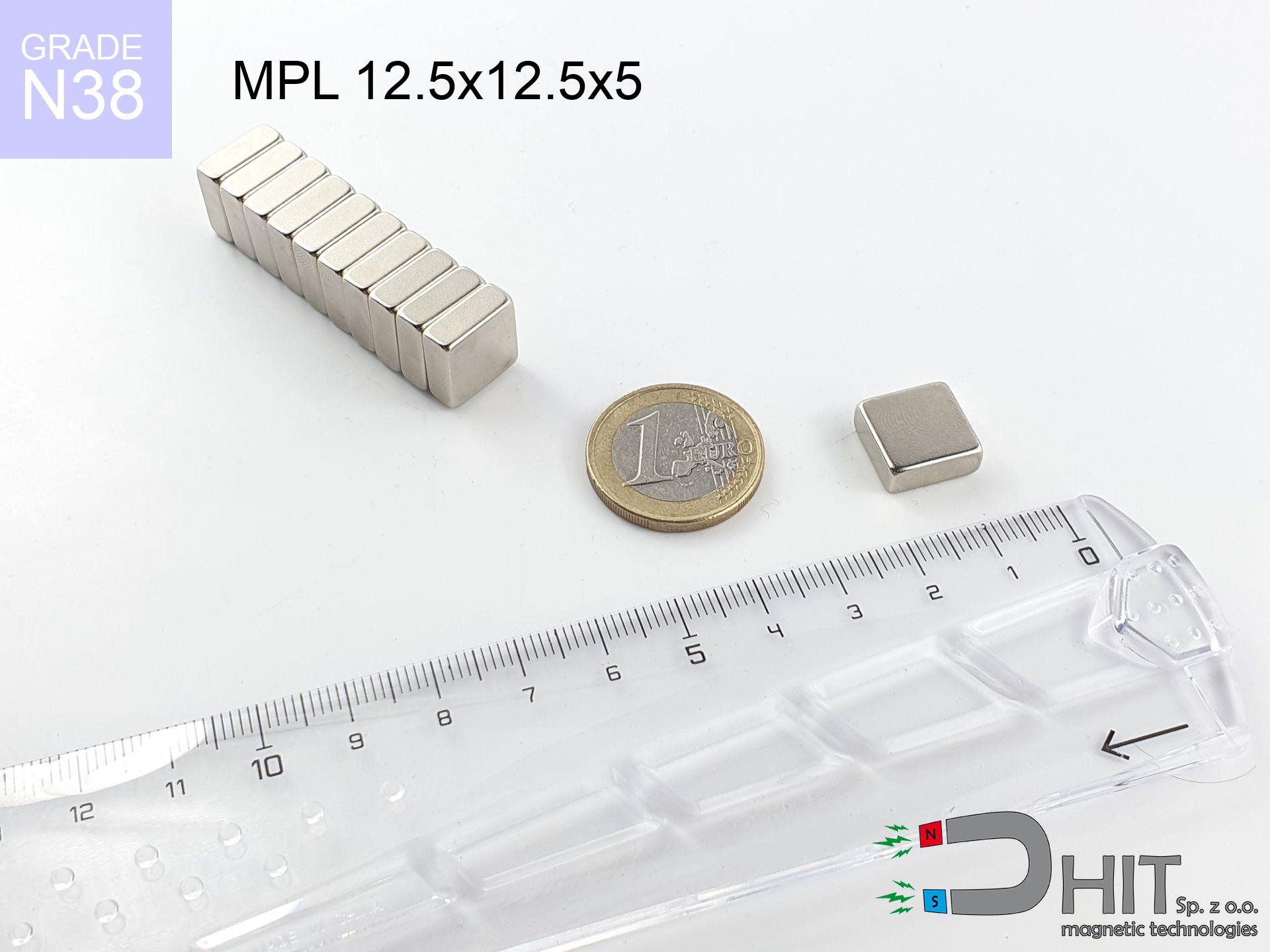
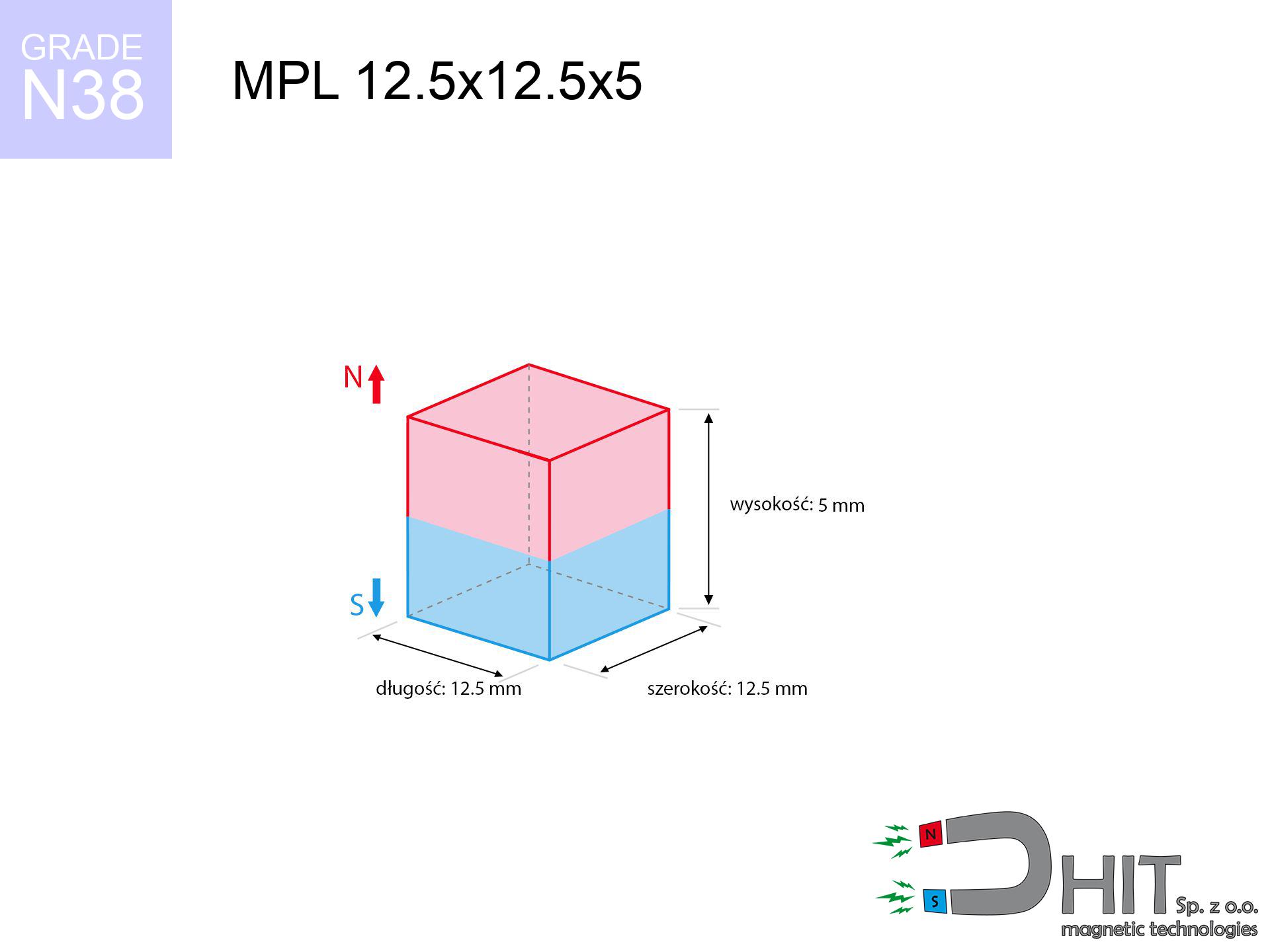
MPL 12.5x12.5x5 / N38 - lamellar magnet
lamellar magnet
Catalog no 020117
GTIN/EAN: 5906301811237
- length
- 12.5 mm [±0,1 mm]
- Width
- 12.5 mm [±0,1 mm]
- Height
- 5 mm [±0,1 mm]
- Weight
- 5.86 g
- Magnetization Direction
- ↑ axial
- Coating
- [NiCuNi] Nickel
2.83 zł with VAT / pcs + price for transport
2.30 zł net + 23% VAT / pcs
bulk discounts:
Need more?Engineering report for this magnet
Full PDF analysis: pull and shear force, effect of distance, temperature and plate thickness, safety distances and the demagnetization curve.
Contact us by phone
+48 22 499 98 98
if you prefer contact us via
request form
the contact form page.
Lifting power as well as form of magnetic components can be estimated using our
power calculator.
Order by 14:00 and we’ll ship today!
Technical - MPL 12.5x12.5x5 / N38 - lamellar magnet
Specification / characteristics - MPL 12.5x12.5x5 / N38 - lamellar magnet
| properties | values |
|---|---|
| Cat. no. | 020117 |
| GTIN/EAN | 5906301811237 |
| Production/Distribution | Dhit sp. z o.o. |
| Country of origin | Poland / China / Germany |
| Customs code | 85059029 |
| length | 12.5 mm [±0,1 mm] |
| Width | 12.5 mm [±0,1 mm] |
| Height | 5 mm [±0,1 mm] |
| Weight | 5.86 g |
| Magnetization Direction | ↑ axial |
| Load capacity ~ ? | 4.84 kg / 47.51 N |
| Magnetic Induction ~ ? | 360.91 mT / 3609 Gs |
| Coating | [NiCuNi] Nickel |
| Manufacturing Tolerance | ±0.1 mm |
Magnetic properties of material N38
| properties | values | units |
|---|---|---|
| remenance Br [min. - max.] ? | 12.2-12.6 | kGs |
| remenance Br [min. - max.] ? | 1220-1260 | mT |
| coercivity bHc ? | 10.8-11.5 | kOe |
| coercivity bHc ? | 860-915 | kA/m |
| actual internal force iHc | ≥ 12 | kOe |
| actual internal force iHc | ≥ 955 | kA/m |
| energy density [min. - max.] ? | 36-38 | BH max MGOe |
| energy density [min. - max.] ? | 287-303 | BH max KJ/m |
| max. temperature ? | ≤ 80 | °C |
Physical properties of sintered neodymium magnets Nd2Fe14B at 20°C
| properties | values | units |
|---|---|---|
| Vickers hardness | ≥550 | Hv |
| Density | ≥7.4 | g/cm3 |
| Curie Temperature TC | 312 - 380 | °C |
| Curie Temperature TF | 593 - 716 | °F |
| Specific resistance | 150 | μΩ⋅cm |
| Bending strength | 250 | MPa |
| Compressive strength | 1000~1100 | MPa |
| Thermal expansion parallel (∥) to orientation (M) | (3-4) x 10-6 | °C-1 |
| Thermal expansion perpendicular (⊥) to orientation (M) | -(1-3) x 10-6 | °C-1 |
| Young's modulus | 1.7 x 10⁴ | kg/mm² |
Technical analysis of the assembly - technical parameters
These data are the outcome of a physical calculation. Values were calculated on models for the material Nd2Fe14B. Real-world conditions may differ. Use these data as a reference point during assembly planning.
Table 1: Static force (force vs distance) - interaction chart
MPL 12.5x12.5x5 / N38
| Distance (mm) | Induction (Gauss) / mT | Pull Force (kg/lbs/g/N) | Risk Status |
|---|---|---|---|
| 0 mm |
3608 Gs
360.8 mT
|
4.84 kg / 10.67 lbs
4840.0 g / 47.5 N
|
warning |
| 1 mm |
3156 Gs
315.6 mT
|
3.70 kg / 8.17 lbs
3704.2 g / 36.3 N
|
warning |
| 2 mm |
2671 Gs
267.1 mT
|
2.65 kg / 5.85 lbs
2653.8 g / 26.0 N
|
warning |
| 3 mm |
2211 Gs
221.1 mT
|
1.82 kg / 4.01 lbs
1817.7 g / 17.8 N
|
safe |
| 5 mm |
1464 Gs
146.4 mT
|
0.80 kg / 1.76 lbs
797.6 g / 7.8 N
|
safe |
| 10 mm |
538 Gs
53.8 mT
|
0.11 kg / 0.24 lbs
107.6 g / 1.1 N
|
safe |
| 15 mm |
234 Gs
23.4 mT
|
0.02 kg / 0.05 lbs
20.4 g / 0.2 N
|
safe |
| 20 mm |
119 Gs
11.9 mT
|
0.01 kg / 0.01 lbs
5.3 g / 0.1 N
|
safe |
| 30 mm |
42 Gs
4.2 mT
|
0.00 kg / 0.00 lbs
0.7 g / 0.0 N
|
safe |
| 50 mm |
10 Gs
1.0 mT
|
0.00 kg / 0.00 lbs
0.0 g / 0.0 N
|
safe |
Table 2: Shear load (wall)
MPL 12.5x12.5x5 / N38
| Distance (mm) | Friction coefficient | Pull Force (kg/lbs/g/N) |
|---|---|---|
| 0 mm | Stal (~0.2) |
0.97 kg / 2.13 lbs
968.0 g / 9.5 N
|
| 1 mm | Stal (~0.2) |
0.74 kg / 1.63 lbs
740.0 g / 7.3 N
|
| 2 mm | Stal (~0.2) |
0.53 kg / 1.17 lbs
530.0 g / 5.2 N
|
| 3 mm | Stal (~0.2) |
0.36 kg / 0.80 lbs
364.0 g / 3.6 N
|
| 5 mm | Stal (~0.2) |
0.16 kg / 0.35 lbs
160.0 g / 1.6 N
|
| 10 mm | Stal (~0.2) |
0.02 kg / 0.05 lbs
22.0 g / 0.2 N
|
| 15 mm | Stal (~0.2) |
0.00 kg / 0.01 lbs
4.0 g / 0.0 N
|
| 20 mm | Stal (~0.2) |
0.00 kg / 0.00 lbs
2.0 g / 0.0 N
|
| 30 mm | Stal (~0.2) |
0.00 kg / 0.00 lbs
0.0 g / 0.0 N
|
| 50 mm | Stal (~0.2) |
0.00 kg / 0.00 lbs
0.0 g / 0.0 N
|
Table 3: Vertical assembly (sliding) - behavior on slippery surfaces
MPL 12.5x12.5x5 / N38
| Surface type | Friction coefficient / % Mocy | Max load (kg/lbs/g/N) |
|---|---|---|
| Raw steel |
µ = 0.3
30% Nominalnej Siły
|
1.45 kg / 3.20 lbs
1452.0 g / 14.2 N
|
| Painted steel (standard) |
µ = 0.2
20% Nominalnej Siły
|
0.97 kg / 2.13 lbs
968.0 g / 9.5 N
|
| Oily/slippery steel |
µ = 0.1
10% Nominalnej Siły
|
0.48 kg / 1.07 lbs
484.0 g / 4.7 N
|
| Magnet with anti-slip rubber |
µ = 0.5
50% Nominalnej Siły
|
2.42 kg / 5.34 lbs
2420.0 g / 23.7 N
|
Table 4: Steel thickness (saturation) - sheet metal selection
MPL 12.5x12.5x5 / N38
| Steel thickness (mm) | % power | Real pull force (kg/lbs/g/N) |
|---|---|---|
| 0.5 mm |
|
0.48 kg / 1.07 lbs
484.0 g / 4.7 N
|
| 1 mm |
|
1.21 kg / 2.67 lbs
1210.0 g / 11.9 N
|
| 2 mm |
|
2.42 kg / 5.34 lbs
2420.0 g / 23.7 N
|
| 3 mm |
|
3.63 kg / 8.00 lbs
3630.0 g / 35.6 N
|
| 5 mm |
|
4.84 kg / 10.67 lbs
4840.0 g / 47.5 N
|
| 10 mm |
|
4.84 kg / 10.67 lbs
4840.0 g / 47.5 N
|
| 11 mm |
|
4.84 kg / 10.67 lbs
4840.0 g / 47.5 N
|
| 12 mm |
|
4.84 kg / 10.67 lbs
4840.0 g / 47.5 N
|
Table 5: Thermal resistance (stability) - power drop
MPL 12.5x12.5x5 / N38
| Ambient temp. (°C) | Power loss | Remaining pull (kg/lbs/g/N) | Status |
|---|---|---|---|
| 20 °C | 0.0% |
4.84 kg / 10.67 lbs
4840.0 g / 47.5 N
|
OK |
| 40 °C | -2.2% |
4.73 kg / 10.44 lbs
4733.5 g / 46.4 N
|
OK |
| 60 °C | -4.4% |
4.63 kg / 10.20 lbs
4627.0 g / 45.4 N
|
|
| 80 °C | -6.6% |
4.52 kg / 9.97 lbs
4520.6 g / 44.3 N
|
|
| 100 °C | -28.8% |
3.45 kg / 7.60 lbs
3446.1 g / 33.8 N
|
Table 6: Two magnets (repulsion) - field collision
MPL 12.5x12.5x5 / N38
| Gap (mm) | Attraction (kg/lbs) (N-S) | Shear Strength (kg/lbs/g/N) | Repulsion (kg/lbs) (N-N) |
|---|---|---|---|
| 0 mm |
12.54 kg / 27.64 lbs
5 069 Gs
|
1.88 kg / 4.15 lbs
1880 g / 18.4 N
|
N/A |
| 1 mm |
11.08 kg / 24.43 lbs
6 783 Gs
|
1.66 kg / 3.66 lbs
1662 g / 16.3 N
|
9.97 kg / 21.98 lbs
~0 Gs
|
| 2 mm |
9.59 kg / 21.15 lbs
6 312 Gs
|
1.44 kg / 3.17 lbs
1439 g / 14.1 N
|
8.63 kg / 19.04 lbs
~0 Gs
|
| 3 mm |
8.18 kg / 18.03 lbs
5 827 Gs
|
1.23 kg / 2.70 lbs
1226 g / 12.0 N
|
7.36 kg / 16.22 lbs
~0 Gs
|
| 5 mm |
5.71 kg / 12.60 lbs
4 871 Gs
|
0.86 kg / 1.89 lbs
857 g / 8.4 N
|
5.14 kg / 11.34 lbs
~0 Gs
|
| 10 mm |
2.07 kg / 4.55 lbs
2 929 Gs
|
0.31 kg / 0.68 lbs
310 g / 3.0 N
|
1.86 kg / 4.10 lbs
~0 Gs
|
| 20 mm |
0.28 kg / 0.61 lbs
1 076 Gs
|
0.04 kg / 0.09 lbs
42 g / 0.4 N
|
0.25 kg / 0.55 lbs
~0 Gs
|
| 50 mm |
0.00 kg / 0.01 lbs
136 Gs
|
0.00 kg / 0.00 lbs
1 g / 0.0 N
|
0.00 kg / 0.00 lbs
~0 Gs
|
| 60 mm |
0.00 kg / 0.00 lbs
84 Gs
|
0.00 kg / 0.00 lbs
0 g / 0.0 N
|
0.00 kg / 0.00 lbs
~0 Gs
|
| 70 mm |
0.00 kg / 0.00 lbs
56 Gs
|
0.00 kg / 0.00 lbs
0 g / 0.0 N
|
0.00 kg / 0.00 lbs
~0 Gs
|
| 80 mm |
0.00 kg / 0.00 lbs
39 Gs
|
0.00 kg / 0.00 lbs
0 g / 0.0 N
|
0.00 kg / 0.00 lbs
~0 Gs
|
| 90 mm |
0.00 kg / 0.00 lbs
28 Gs
|
0.00 kg / 0.00 lbs
0 g / 0.0 N
|
0.00 kg / 0.00 lbs
~0 Gs
|
| 100 mm |
0.00 kg / 0.00 lbs
21 Gs
|
0.00 kg / 0.00 lbs
0 g / 0.0 N
|
0.00 kg / 0.00 lbs
~0 Gs
|
Table 7: Safety (HSE) (electronics) - precautionary measures
MPL 12.5x12.5x5 / N38
| Object / Device | Limit (Gauss) / mT | Safe distance |
|---|---|---|
| Pacemaker | 5 Gs (0.5 mT) | 6.5 cm |
| Hearing aid | 10 Gs (1.0 mT) | 5.5 cm |
| Timepiece | 20 Gs (2.0 mT) | 4.0 cm |
| Mobile device | 40 Gs (4.0 mT) | 3.5 cm |
| Car key | 50 Gs (5.0 mT) | 3.0 cm |
| Payment card | 400 Gs (40.0 mT) | 1.5 cm |
| HDD hard drive | 600 Gs (60.0 mT) | 1.0 cm |
Table 8: Impact energy (kinetic energy) - collision effects
MPL 12.5x12.5x5 / N38
| Start from (mm) | Speed (km/h) | Energy (J) | Predicted outcome |
|---|---|---|---|
| 10 mm |
24.51 km/h
(6.81 m/s)
|
0.14 J | |
| 30 mm |
24.80 km/h
(6.89 m/s)
|
0.14 J | |
| 50 mm |
24.80 km/h
(6.89 m/s)
|
0.14 J | |
| 100 mm |
24.81 km/h
(6.89 m/s)
|
0.14 J |
Table 9: Surface protection spec
MPL 12.5x12.5x5 / N38
| Technical parameter | Value / Description |
|---|---|
| Coating type | [NiCuNi] Nickel |
| Layer structure | Nickel - Copper - Nickel |
| Layer thickness | 10-20 µm |
| Salt spray test (SST) ? | 24 h |
| Recommended environment | Indoors only (dry) |
Table 10: Construction data (Pc)
MPL 12.5x12.5x5 / N38
| Parameter | Value | SI Unit / Description |
|---|---|---|
| Magnetic Flux | 5 874 Mx | 58.7 µWb |
| Pc Coefficient | 0.46 | Low (Flat) |
Table 11: Hydrostatics and buoyancy
MPL 12.5x12.5x5 / N38
| Environment | Effective steel pull | Effect |
|---|---|---|
| Air (land) | 4.84 kg | Standard |
| Water (riverbed) |
5.54 kg
(+0.70 kg buoyancy gain)
|
+14.5% |
1. Vertical hold
*Caution: On a vertical wall, the magnet retains just ~20% of its max power.
2. Steel thickness impact
*Thin metal sheet (e.g. computer case) severely reduces the holding force.
3. Temperature resistance
*For standard magnets, the max working temp is 80°C.
4. Demagnetization curve and operating point (B-H)
chart generated for the permeance coefficient Pc (Permeance Coefficient) = 0.46
This simulation demonstrates the magnetic stability of the selected magnet under specific geometric conditions. The solid red line represents the demagnetization curve (material potential), while the dashed blue line is the load line based on the magnet's geometry. The Pc (Permeance Coefficient), also known as the load line slope, is a dimensionless value that describes the relationship between the magnet's shape and its magnetic stability. The intersection of these two lines (the black dot) is the operating point — it determines the actual magnetic flux density generated by the magnet in this specific configuration. A higher Pc value means the magnet is more 'slender' (tall relative to its area), resulting in a higher operating point and better resistance to irreversible demagnetization caused by external fields or temperature. A value of 0.42 is relatively low (typical for flat magnets), meaning the operating point is closer to the 'knee' of the curve — caution is advised when operating at temperatures near the maximum limit to avoid strength loss.
Elemental analysis
| iron (Fe) | 64% – 68% |
| neodymium (Nd) | 29% – 32% |
| boron (B) | 1.1% – 1.2% |
| dysprosium (Dy) | 0.5% – 2.0% |
| coating (Ni-Cu-Ni) | < 0.05% |
Ecology and recycling (GPSR)
| recyclability (EoL) | 100% |
| recycled raw materials | ~10% (pre-cons) |
| carbon footprint | low / zredukowany |
| waste code (EWC) | 16 02 16 |
Other offers

![SM 32x225 [2xM8] / N52 - magnetic separator](https://cdn3.dhit.pl/graphics/products/sm-32x225-2xm8-zix.jpg "SM 32x225 [2xM8] / N52 - magnetic separator")


Strengths as well as weaknesses of neodymium magnets.
Benefits
- Their strength remains stable, and after approximately ten years it decreases only by ~1% (according to research),
- They maintain their magnetic properties even under close interference source,
- The use of an aesthetic coating of noble metals (nickel, gold, silver) causes the element to have aesthetics,
- Magnets have exceptionally strong magnetic induction on the surface,
- Made from properly selected components, these magnets show impressive resistance to high heat, enabling them to function (depending on their form) at temperatures up to 230°C and above...
- Considering the ability of flexible shaping and customization to custom needs, NdFeB magnets can be produced in a variety of forms and dimensions, which increases their versatility,
- Huge importance in high-tech industry – they are used in computer drives, drive modules, medical equipment, also modern systems.
- Relatively small size with high pulling force – neodymium magnets offer strong magnetic field in compact dimensions, which makes them useful in miniature devices
Limitations
- At very strong impacts they can break, therefore we recommend placing them in strong housings. A metal housing provides additional protection against damage and increases the magnet's durability.
- Neodymium magnets lose force when exposed to high temperatures. After reaching 80°C, many of them experience permanent drop of strength (a factor is the shape and dimensions of the magnet). We offer magnets specially adapted to work at temperatures up to 230°C marked [AH], which are very resistant to heat
- Due to the susceptibility of magnets to corrosion in a humid environment, we advise using waterproof magnets made of rubber, plastic or other material resistant to moisture, in case of application outdoors
- We recommend a housing - magnetic mechanism, due to difficulties in realizing nuts inside the magnet and complex forms.
- Potential hazard resulting from small fragments of magnets pose a threat, if swallowed, which becomes key in the aspect of protecting the youngest. It is also worth noting that small components of these devices are able to complicate diagnosis medical when they are in the body.
- Due to complex production process, their price exceeds standard values,
Lifting parameters
Best holding force of the magnet in ideal parameters – what contributes to it?
- on a plate made of mild steel, perfectly concentrating the magnetic field
- with a cross-section no less than 10 mm
- characterized by lack of roughness
- under conditions of ideal adhesion (surface-to-surface)
- during detachment in a direction perpendicular to the plane
- at temperature room level
Lifting capacity in practice – influencing factors
- Gap (between the magnet and the plate), since even a microscopic clearance (e.g. 0.5 mm) results in a decrease in lifting capacity by up to 50% (this also applies to varnish, rust or dirt).
- Pull-off angle – note that the magnet has greatest strength perpendicularly. Under shear forces, the capacity drops significantly, often to levels of 20-30% of the nominal value.
- Element thickness – to utilize 100% power, the steel must be adequately massive. Thin sheet restricts the attraction force (the magnet "punches through" it).
- Metal type – not every steel attracts identically. High carbon content weaken the attraction effect.
- Surface finish – ideal contact is possible only on smooth steel. Rough texture create air cushions, reducing force.
- Thermal conditions – neodymium magnets have a negative temperature coefficient. At higher temperatures they lose power, and at low temperatures gain strength (up to a certain limit).
Lifting capacity testing was conducted on a smooth plate of optimal thickness, under a perpendicular pulling force, whereas under parallel forces the lifting capacity is smaller. In addition, even a slight gap between the magnet’s surface and the plate reduces the lifting capacity.
Warnings
Protect data
Data protection: Strong magnets can damage payment cards and sensitive devices (heart implants, medical aids, timepieces).
Fragile material
Despite metallic appearance, neodymium is brittle and cannot withstand shocks. Do not hit, as the magnet may crumble into hazardous fragments.
Conscious usage
Before use, check safety instructions. Uncontrolled attraction can destroy the magnet or injure your hand. Be predictive.
Do not drill into magnets
Powder created during grinding of magnets is flammable. Do not drill into magnets without proper cooling and knowledge.
Nickel allergy
A percentage of the population have a contact allergy to nickel, which is the typical protective layer for neodymium magnets. Extended handling can result in an allergic reaction. We recommend wear protective gloves.
Bone fractures
Watch your fingers. Two powerful magnets will snap together instantly with a force of massive weight, destroying everything in their path. Be careful!
GPS Danger
A powerful magnetic field negatively affects the functioning of magnetometers in phones and GPS navigation. Keep magnets close to a device to avoid breaking the sensors.
Maximum temperature
Monitor thermal conditions. Heating the magnet to high heat will destroy its properties and pulling force.
Swallowing risk
Product intended for adults. Tiny parts pose a choking risk, leading to severe trauma. Keep out of reach of kids and pets.
Danger to pacemakers
Health Alert: Strong magnets can deactivate heart devices and defibrillators. Do not approach if you have medical devices.
Tabela kosztu i czasu dostawy
Płatność przed wysyłką:

GLS kurier
Przesyłka będzie u Ciebie za 2-3 dni
14.99 ZŁ

InPost Paczkomaty 24/7
Przesyłka będzie u Ciebie za 1-2 dni
12.30 ZŁ
Płatność przy odbiorze (pobranie):
GLS kurier
Przesyłka będzie u Ciebie za 1-2 dni
23.00 ZŁ
Rate the product
Your rating