

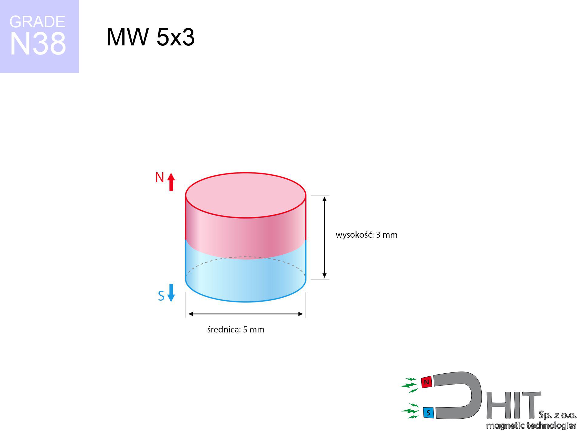
MW 5x3 / N38 - cylindrical magnet
cylindrical magnet
Catalog no 010087
GTIN/EAN: 5906301810865
Diameter Ø
5 mm [±0,1 mm]
Height
3 mm [±0,1 mm]
Weight
0.44 g
Magnetization Direction
↑ axial
Load capacity
0.84 kg / 8.25 N
Magnetic Induction
475.16 mT / 4752 Gs
Coating
[NiCuNi] Nickel
0.283 ZŁ with VAT / pcs + price for transport
0.230 ZŁ net + 23% VAT / pcs
bulk discounts:
Need more?
Pick up the phone and ask
+48 888 99 98 98
otherwise drop us a message using
form
the contact form page.
Strength along with shape of neodymium magnets can be estimated using our
online calculation tool.
Order by 14:00 and we’ll ship today!
Technical - MW 5x3 / N38 - cylindrical magnet
Specification / characteristics - MW 5x3 / N38 - cylindrical magnet
| properties | values |
|---|---|
| Cat. no. | 010087 |
| GTIN/EAN | 5906301810865 |
| Production/Distribution | Dhit sp. z o.o. |
| Country of origin | Poland / China / Germany |
| Customs code | 85059029 |
| Diameter Ø | 5 mm [±0,1 mm] |
| Height | 3 mm [±0,1 mm] |
| Weight | 0.44 g |
| Magnetization Direction | ↑ axial |
| Load capacity ~ ? | 0.84 kg / 8.25 N |
| Magnetic Induction ~ ? | 475.16 mT / 4752 Gs |
| Coating | [NiCuNi] Nickel |
| Manufacturing Tolerance | ±0.1 mm |
Magnetic properties of material N38
| properties | values | units |
|---|---|---|
| remenance Br [min. - max.] ? | 12.2-12.6 | kGs |
| remenance Br [min. - max.] ? | 1220-1260 | mT |
| coercivity bHc ? | 10.8-11.5 | kOe |
| coercivity bHc ? | 860-915 | kA/m |
| actual internal force iHc | ≥ 12 | kOe |
| actual internal force iHc | ≥ 955 | kA/m |
| energy density [min. - max.] ? | 36-38 | BH max MGOe |
| energy density [min. - max.] ? | 287-303 | BH max KJ/m |
| max. temperature ? | ≤ 80 | °C |
Physical properties of sintered neodymium magnets Nd2Fe14B at 20°C
| properties | values | units |
|---|---|---|
| Vickers hardness | ≥550 | Hv |
| Density | ≥7.4 | g/cm3 |
| Curie Temperature TC | 312 - 380 | °C |
| Curie Temperature TF | 593 - 716 | °F |
| Specific resistance | 150 | μΩ⋅cm |
| Bending strength | 250 | MPa |
| Compressive strength | 1000~1100 | MPa |
| Thermal expansion parallel (∥) to orientation (M) | (3-4) x 10-6 | °C-1 |
| Thermal expansion perpendicular (⊥) to orientation (M) | -(1-3) x 10-6 | °C-1 |
| Young's modulus | 1.7 x 10⁴ | kg/mm² |
Engineering analysis of the product - report
These values represent the direct effect of a physical calculation. Values are based on models for the class Nd2Fe14B. Actual performance may differ from theoretical values. Use these data as a reference point during assembly planning.
Table 1: Static force (pull vs gap) - characteristics
MW 5x3 / N38
| Distance (mm) | Induction (Gauss) / mT | Pull Force (kg/lbs/g/N) | Risk Status |
|---|---|---|---|
| 0 mm |
4745 Gs
474.5 mT
|
0.84 kg / 1.85 lbs
840.0 g / 8.2 N
|
safe |
| 1 mm |
2955 Gs
295.5 mT
|
0.33 kg / 0.72 lbs
325.8 g / 3.2 N
|
safe |
| 2 mm |
1672 Gs
167.2 mT
|
0.10 kg / 0.23 lbs
104.4 g / 1.0 N
|
safe |
| 3 mm |
960 Gs
96.0 mT
|
0.03 kg / 0.08 lbs
34.4 g / 0.3 N
|
safe |
| 5 mm |
372 Gs
37.2 mT
|
0.01 kg / 0.01 lbs
5.2 g / 0.1 N
|
safe |
| 10 mm |
74 Gs
7.4 mT
|
0.00 kg / 0.00 lbs
0.2 g / 0.0 N
|
safe |
| 15 mm |
25 Gs
2.5 mT
|
0.00 kg / 0.00 lbs
0.0 g / 0.0 N
|
safe |
| 20 mm |
12 Gs
1.2 mT
|
0.00 kg / 0.00 lbs
0.0 g / 0.0 N
|
safe |
| 30 mm |
4 Gs
0.4 mT
|
0.00 kg / 0.00 lbs
0.0 g / 0.0 N
|
safe |
| 50 mm |
1 Gs
0.1 mT
|
0.00 kg / 0.00 lbs
0.0 g / 0.0 N
|
safe |
Table 2: Slippage hold (vertical surface)
MW 5x3 / N38
| Distance (mm) | Friction coefficient | Pull Force (kg/lbs/g/N) |
|---|---|---|
| 0 mm | Stal (~0.2) |
0.17 kg / 0.37 lbs
168.0 g / 1.6 N
|
| 1 mm | Stal (~0.2) |
0.07 kg / 0.15 lbs
66.0 g / 0.6 N
|
| 2 mm | Stal (~0.2) |
0.02 kg / 0.04 lbs
20.0 g / 0.2 N
|
| 3 mm | Stal (~0.2) |
0.01 kg / 0.01 lbs
6.0 g / 0.1 N
|
| 5 mm | Stal (~0.2) |
0.00 kg / 0.00 lbs
2.0 g / 0.0 N
|
| 10 mm | Stal (~0.2) |
0.00 kg / 0.00 lbs
0.0 g / 0.0 N
|
| 15 mm | Stal (~0.2) |
0.00 kg / 0.00 lbs
0.0 g / 0.0 N
|
| 20 mm | Stal (~0.2) |
0.00 kg / 0.00 lbs
0.0 g / 0.0 N
|
| 30 mm | Stal (~0.2) |
0.00 kg / 0.00 lbs
0.0 g / 0.0 N
|
| 50 mm | Stal (~0.2) |
0.00 kg / 0.00 lbs
0.0 g / 0.0 N
|
Table 3: Vertical assembly (sliding) - vertical pull
MW 5x3 / N38
| Surface type | Friction coefficient / % Mocy | Max load (kg/lbs/g/N) |
|---|---|---|
| Raw steel |
µ = 0.3
30% Nominalnej Siły
|
0.25 kg / 0.56 lbs
252.0 g / 2.5 N
|
| Painted steel (standard) |
µ = 0.2
20% Nominalnej Siły
|
0.17 kg / 0.37 lbs
168.0 g / 1.6 N
|
| Oily/slippery steel |
µ = 0.1
10% Nominalnej Siły
|
0.08 kg / 0.19 lbs
84.0 g / 0.8 N
|
| Magnet with anti-slip rubber |
µ = 0.5
50% Nominalnej Siły
|
0.42 kg / 0.93 lbs
420.0 g / 4.1 N
|
Table 4: Steel thickness (saturation) - power losses
MW 5x3 / N38
| Steel thickness (mm) | % power | Real pull force (kg/lbs/g/N) |
|---|---|---|
| 0.5 mm |
|
0.08 kg / 0.19 lbs
84.0 g / 0.8 N
|
| 1 mm |
|
0.21 kg / 0.46 lbs
210.0 g / 2.1 N
|
| 2 mm |
|
0.42 kg / 0.93 lbs
420.0 g / 4.1 N
|
| 3 mm |
|
0.63 kg / 1.39 lbs
630.0 g / 6.2 N
|
| 5 mm |
|
0.84 kg / 1.85 lbs
840.0 g / 8.2 N
|
| 10 mm |
|
0.84 kg / 1.85 lbs
840.0 g / 8.2 N
|
| 11 mm |
|
0.84 kg / 1.85 lbs
840.0 g / 8.2 N
|
| 12 mm |
|
0.84 kg / 1.85 lbs
840.0 g / 8.2 N
|
Table 5: Thermal stability (stability) - thermal limit
MW 5x3 / N38
| Ambient temp. (°C) | Power loss | Remaining pull (kg/lbs/g/N) | Status |
|---|---|---|---|
| 20 °C | 0.0% |
0.84 kg / 1.85 lbs
840.0 g / 8.2 N
|
OK |
| 40 °C | -2.2% |
0.82 kg / 1.81 lbs
821.5 g / 8.1 N
|
OK |
| 60 °C | -4.4% |
0.80 kg / 1.77 lbs
803.0 g / 7.9 N
|
OK |
| 80 °C | -6.6% |
0.78 kg / 1.73 lbs
784.6 g / 7.7 N
|
|
| 100 °C | -28.8% |
0.60 kg / 1.32 lbs
598.1 g / 5.9 N
|
Table 6: Magnet-Magnet interaction (repulsion) - forces in the system
MW 5x3 / N38
| Gap (mm) | Attraction (kg/lbs) (N-S) | Shear Force (kg/lbs/g/N) | Repulsion (kg/lbs) (N-N) |
|---|---|---|---|
| 0 mm |
2.73 kg / 6.01 lbs
5 700 Gs
|
0.41 kg / 0.90 lbs
409 g / 4.0 N
|
N/A |
| 1 mm |
1.77 kg / 3.91 lbs
7 658 Gs
|
0.27 kg / 0.59 lbs
266 g / 2.6 N
|
1.60 kg / 3.52 lbs
~0 Gs
|
| 2 mm |
1.06 kg / 2.33 lbs
5 910 Gs
|
0.16 kg / 0.35 lbs
159 g / 1.6 N
|
0.95 kg / 2.10 lbs
~0 Gs
|
| 3 mm |
0.60 kg / 1.33 lbs
4 460 Gs
|
0.09 kg / 0.20 lbs
90 g / 0.9 N
|
0.54 kg / 1.19 lbs
~0 Gs
|
| 5 mm |
0.19 kg / 0.42 lbs
2 520 Gs
|
0.03 kg / 0.06 lbs
29 g / 0.3 N
|
0.17 kg / 0.38 lbs
~0 Gs
|
| 10 mm |
0.02 kg / 0.04 lbs
745 Gs
|
0.00 kg / 0.01 lbs
3 g / 0.0 N
|
0.02 kg / 0.03 lbs
~0 Gs
|
| 20 mm |
0.00 kg / 0.00 lbs
147 Gs
|
0.00 kg / 0.00 lbs
0 g / 0.0 N
|
0.00 kg / 0.00 lbs
~0 Gs
|
| 50 mm |
0.00 kg / 0.00 lbs
12 Gs
|
0.00 kg / 0.00 lbs
0 g / 0.0 N
|
0.00 kg / 0.00 lbs
~0 Gs
|
| 60 mm |
0.00 kg / 0.00 lbs
7 Gs
|
0.00 kg / 0.00 lbs
0 g / 0.0 N
|
0.00 kg / 0.00 lbs
~0 Gs
|
| 70 mm |
0.00 kg / 0.00 lbs
5 Gs
|
0.00 kg / 0.00 lbs
0 g / 0.0 N
|
0.00 kg / 0.00 lbs
~0 Gs
|
| 80 mm |
0.00 kg / 0.00 lbs
3 Gs
|
0.00 kg / 0.00 lbs
0 g / 0.0 N
|
0.00 kg / 0.00 lbs
~0 Gs
|
| 90 mm |
0.00 kg / 0.00 lbs
2 Gs
|
0.00 kg / 0.00 lbs
0 g / 0.0 N
|
0.00 kg / 0.00 lbs
~0 Gs
|
| 100 mm |
0.00 kg / 0.00 lbs
2 Gs
|
0.00 kg / 0.00 lbs
0 g / 0.0 N
|
0.00 kg / 0.00 lbs
~0 Gs
|
Table 7: Protective zones (electronics) - precautionary measures
MW 5x3 / N38
| Object / Device | Limit (Gauss) / mT | Safe distance |
|---|---|---|
| Pacemaker | 5 Gs (0.5 mT) | 3.0 cm |
| Hearing aid | 10 Gs (1.0 mT) | 2.5 cm |
| Mechanical watch | 20 Gs (2.0 mT) | 2.0 cm |
| Mobile device | 40 Gs (4.0 mT) | 1.5 cm |
| Remote | 50 Gs (5.0 mT) | 1.5 cm |
| Payment card | 400 Gs (40.0 mT) | 0.5 cm |
| HDD hard drive | 600 Gs (60.0 mT) | 0.5 cm |
Table 8: Dynamics (kinetic energy) - collision effects
MW 5x3 / N38
| Start from (mm) | Speed (km/h) | Energy (J) | Predicted outcome |
|---|---|---|---|
| 10 mm |
44.07 km/h
(12.24 m/s)
|
0.03 J | |
| 30 mm |
76.32 km/h
(21.20 m/s)
|
0.10 J | |
| 50 mm |
98.53 km/h
(27.37 m/s)
|
0.16 J | |
| 100 mm |
139.35 km/h
(38.71 m/s)
|
0.33 J |
Table 9: Anti-corrosion coating durability
MW 5x3 / N38
| Technical parameter | Value / Description |
|---|---|
| Coating type | [NiCuNi] Nickel |
| Layer structure | Nickel - Copper - Nickel |
| Layer thickness | 10-20 µm |
| Salt spray test (SST) ? | 24 h |
| Recommended environment | Indoors only (dry) |
Table 10: Electrical data (Pc)
MW 5x3 / N38
| Parameter | Value | SI Unit / Description |
|---|---|---|
| Magnetic Flux | 942 Mx | 9.4 µWb |
| Pc Coefficient | 0.66 | High (Stable) |
Table 11: Submerged application
MW 5x3 / N38
| Environment | Effective steel pull | Effect |
|---|---|---|
| Air (land) | 0.84 kg | Standard |
| Water (riverbed) |
0.96 kg
(+0.12 kg buoyancy gain)
|
+14.5% |
1. Wall mount (shear)
*Note: On a vertical wall, the magnet holds merely a fraction of its perpendicular strength.
2. Plate thickness effect
*Thin metal sheet (e.g. 0.5mm PC case) severely weakens the holding force.
3. Temperature resistance
*For standard magnets, the critical limit is 80°C.
4. Demagnetization curve and operating point (B-H)
chart generated for the permeance coefficient Pc (Permeance Coefficient) = 0.66
The chart above illustrates the magnetic characteristics of the material within the second quadrant of the hysteresis loop. The solid red line represents the demagnetization curve (material potential), while the dashed blue line is the load line based on the magnet's geometry. The Pc (Permeance Coefficient), also known as the load line slope, is a dimensionless value that describes the relationship between the magnet's shape and its magnetic stability. The intersection of these two lines (the black dot) is the operating point — it determines the actual magnetic flux density generated by the magnet in this specific configuration. A higher Pc value means the magnet is more 'slender' (tall relative to its area), resulting in a higher operating point and better resistance to irreversible demagnetization caused by external fields or temperature. A value of 0.42 is relatively low (typical for flat magnets), meaning the operating point is closer to the 'knee' of the curve — caution is advised when operating at temperatures near the maximum limit to avoid strength loss.
Chemical composition
| iron (Fe) | 64% – 68% |
| neodymium (Nd) | 29% – 32% |
| boron (B) | 1.1% – 1.2% |
| dysprosium (Dy) | 0.5% – 2.0% |
| coating (Ni-Cu-Ni) | < 0.05% |
Environmental data
| recyclability (EoL) | 100% |
| recycled raw materials | ~10% (pre-cons) |
| carbon footprint | low / zredukowany |
| waste code (EWC) | 16 02 16 |
Check out also deals
![UMP 75x25 [M10x3] GW F200 PLATINIUM / N52 - search holder](https://cdn3.dhit.pl/graphics/products/ump-75x25-m10x3-gw-f200-platinium-tav.jpg "UMP 75x25 [M10x3] GW F200 PLATINIUM / N52 - search holder")
![SM 25x175 [2xM8] / N42 - magnetic separator](https://cdn3.dhit.pl/graphics/products/sm-25x175-2xm8-fux.jpg "SM 25x175 [2xM8] / N42 - magnetic separator")
![SM 32x350 [2xM8] / N52 - magnetic separator](https://cdn3.dhit.pl/graphics/products/sm-32x350-2xm8-fag.jpg "SM 32x350 [2xM8] / N52 - magnetic separator")
![MPL 40x15x5x2[7/3.5] / N38 - lamellar magnet](https://cdn3.dhit.pl/graphics/products/mpl-40x15x5x27-3.5-cas.jpg "MPL 40x15x5x2[7/3.5] / N38 - lamellar magnet")
Advantages as well as disadvantages of neodymium magnets.
Pros
- They retain attractive force for almost ten years – the drop is just ~1% (based on simulations),
- They retain their magnetic properties even under external field action,
- Thanks to the smooth finish, the plating of nickel, gold, or silver-plated gives an modern appearance,
- They show high magnetic induction at the operating surface, which affects their effectiveness,
- Neodymium magnets are characterized by extremely high magnetic induction on the magnet surface and are able to act (depending on the form) even at a temperature of 230°C or more...
- In view of the option of flexible molding and customization to unique requirements, NdFeB magnets can be created in a wide range of geometric configurations, which expands the range of possible applications,
- Versatile presence in future technologies – they find application in hard drives, electromotive mechanisms, medical devices, and modern systems.
- Compactness – despite small sizes they offer powerful magnetic field, making them ideal for precision applications
Weaknesses
- To avoid cracks under impact, we recommend using special steel housings. Such a solution secures the magnet and simultaneously improves its durability.
- Neodymium magnets lose their power under the influence of heating. As soon as 80°C is exceeded, many of them start losing their force. Therefore, we recommend our special magnets marked [AH], which maintain durability even at temperatures up to 230°C
- Due to the susceptibility of magnets to corrosion in a humid environment, we advise using waterproof magnets made of rubber, plastic or other material resistant to moisture, in case of application outdoors
- Limited possibility of producing threads in the magnet and complex shapes - recommended is casing - magnetic holder.
- Health risk resulting from small fragments of magnets are risky, when accidentally swallowed, which gains importance in the context of child health protection. Furthermore, small components of these magnets are able to disrupt the diagnostic process medical after entering the body.
- Higher cost of purchase is a significant factor to consider compared to ceramic magnets, especially in budget applications
Holding force characteristics
Optimal lifting capacity of a neodymium magnet – what it depends on?
- with the contact of a sheet made of low-carbon steel, guaranteeing full magnetic saturation
- whose thickness is min. 10 mm
- characterized by smoothness
- without any clearance between the magnet and steel
- under axial force direction (90-degree angle)
- at ambient temperature approx. 20 degrees Celsius
Determinants of practical lifting force of a magnet
- Space between surfaces – every millimeter of distance (caused e.g. by veneer or dirt) significantly weakens the magnet efficiency, often by half at just 0.5 mm.
- Load vector – highest force is obtained only during pulling at a 90° angle. The resistance to sliding of the magnet along the surface is typically many times lower (approx. 1/5 of the lifting capacity).
- Steel thickness – insufficiently thick plate does not accept the full field, causing part of the power to be wasted into the air.
- Chemical composition of the base – mild steel gives the best results. Higher carbon content decrease magnetic permeability and lifting capacity.
- Surface condition – smooth surfaces ensure maximum contact, which improves field saturation. Rough surfaces reduce efficiency.
- Temperature influence – high temperature reduces pulling force. Too high temperature can permanently damage the magnet.
Holding force was tested on the plate surface of 20 mm thickness, when a perpendicular force was applied, whereas under parallel forces the holding force is lower. Moreover, even a minimal clearance between the magnet and the plate lowers the lifting capacity.
Precautions when working with neodymium magnets
Skin irritation risks
Certain individuals experience a sensitization to nickel, which is the common plating for NdFeB magnets. Extended handling might lead to an allergic reaction. We suggest use protective gloves.
Do not drill into magnets
Dust generated during cutting of magnets is flammable. Avoid drilling into magnets without proper cooling and knowledge.
Demagnetization risk
Do not overheat. NdFeB magnets are sensitive to heat. If you need operation above 80°C, look for special high-temperature series (H, SH, UH).
ICD Warning
For implant holders: Powerful magnets affect electronics. Keep at least 30 cm distance or request help to handle the magnets.
Compass and GPS
Be aware: neodymium magnets produce a field that interferes with precision electronics. Maintain a safe distance from your mobile, device, and GPS.
Protective goggles
Beware of splinters. Magnets can fracture upon violent connection, ejecting sharp fragments into the air. Wear goggles.
Physical harm
Risk of injury: The pulling power is so great that it can cause blood blisters, crushing, and broken bones. Protective gloves are recommended.
Electronic hazard
Avoid bringing magnets close to a purse, laptop, or screen. The magnetism can irreversibly ruin these devices and wipe information from cards.
Choking Hazard
Product intended for adults. Small elements can be swallowed, causing serious injuries. Keep out of reach of kids and pets.
Handling rules
Exercise caution. Neodymium magnets act from a long distance and snap with huge force, often quicker than you can move away.
Tabela kosztu i czasu dostawy
Płatność przed wysyłką:

GLS kurier
Przesyłka będzie u Ciebie za 2-3 dni
14.99 ZŁ

InPost Paczkomaty 24/7
Przesyłka będzie u Ciebie za 1-2 dni
12.30 ZŁ
Płatność przy odbiorze (pobranie):
GLS kurier
Przesyłka będzie u Ciebie za 1-2 dni
23.00 ZŁ
Rate the product
Your rating