

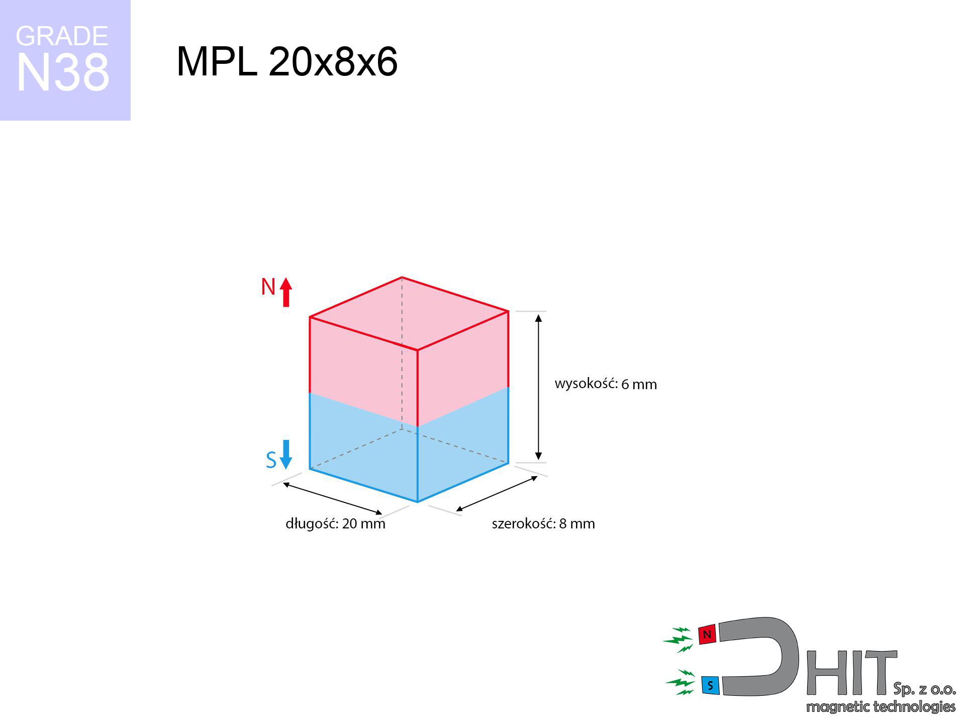
MPL 20x8x6 / N38 - lamellar magnet
lamellar magnet
Catalog no 020134
GTIN/EAN: 5906301811404
length
20 mm [±0,1 mm]
Width
8 mm [±0,1 mm]
Height
6 mm [±0,1 mm]
Weight
7.2 g
Magnetization Direction
↑ axial
Load capacity
6.27 kg / 61.50 N
Magnetic Induction
423.90 mT / 4239 Gs
Coating
[NiCuNi] Nickel
5.17 ZŁ with VAT / pcs + price for transport
4.20 ZŁ net + 23% VAT / pcs
bulk discounts:
Need more?
Call us
+48 888 99 98 98
alternatively get in touch through
form
through our site.
Parameters along with shape of magnets can be checked on our
magnetic calculator.
Same-day shipping for orders placed before 14:00.
Product card - MPL 20x8x6 / N38 - lamellar magnet
Specification / characteristics - MPL 20x8x6 / N38 - lamellar magnet
| properties | values |
|---|---|
| Cat. no. | 020134 |
| GTIN/EAN | 5906301811404 |
| Production/Distribution | Dhit sp. z o.o. |
| Country of origin | Poland / China / Germany |
| Customs code | 85059029 |
| length | 20 mm [±0,1 mm] |
| Width | 8 mm [±0,1 mm] |
| Height | 6 mm [±0,1 mm] |
| Weight | 7.2 g |
| Magnetization Direction | ↑ axial |
| Load capacity ~ ? | 6.27 kg / 61.50 N |
| Magnetic Induction ~ ? | 423.90 mT / 4239 Gs |
| Coating | [NiCuNi] Nickel |
| Manufacturing Tolerance | ±0.1 mm |
Magnetic properties of material N38
| properties | values | units |
|---|---|---|
| remenance Br [min. - max.] ? | 12.2-12.6 | kGs |
| remenance Br [min. - max.] ? | 1220-1260 | mT |
| coercivity bHc ? | 10.8-11.5 | kOe |
| coercivity bHc ? | 860-915 | kA/m |
| actual internal force iHc | ≥ 12 | kOe |
| actual internal force iHc | ≥ 955 | kA/m |
| energy density [min. - max.] ? | 36-38 | BH max MGOe |
| energy density [min. - max.] ? | 287-303 | BH max KJ/m |
| max. temperature ? | ≤ 80 | °C |
Physical properties of sintered neodymium magnets Nd2Fe14B at 20°C
| properties | values | units |
|---|---|---|
| Vickers hardness | ≥550 | Hv |
| Density | ≥7.4 | g/cm3 |
| Curie Temperature TC | 312 - 380 | °C |
| Curie Temperature TF | 593 - 716 | °F |
| Specific resistance | 150 | μΩ⋅cm |
| Bending strength | 250 | MPa |
| Compressive strength | 1000~1100 | MPa |
| Thermal expansion parallel (∥) to orientation (M) | (3-4) x 10-6 | °C-1 |
| Thermal expansion perpendicular (⊥) to orientation (M) | -(1-3) x 10-6 | °C-1 |
| Young's modulus | 1.7 x 10⁴ | kg/mm² |
Technical modeling of the magnet - report
Presented information are the outcome of a engineering simulation. Values were calculated on algorithms for the material Nd2Fe14B. Real-world parameters may differ. Treat these calculations as a supplementary guide when designing systems.
Table 1: Static force (force vs distance) - characteristics
MPL 20x8x6 / N38
| Distance (mm) | Induction (Gauss) / mT | Pull Force (kg/lbs/g/N) | Risk Status |
|---|---|---|---|
| 0 mm |
4236 Gs
423.6 mT
|
6.27 kg / 13.82 LBS
6270.0 g / 61.5 N
|
warning |
| 1 mm |
3505 Gs
350.5 mT
|
4.29 kg / 9.47 LBS
4293.5 g / 42.1 N
|
warning |
| 2 mm |
2814 Gs
281.4 mT
|
2.77 kg / 6.10 LBS
2766.9 g / 27.1 N
|
warning |
| 3 mm |
2235 Gs
223.5 mT
|
1.75 kg / 3.85 LBS
1745.9 g / 17.1 N
|
safe |
| 5 mm |
1425 Gs
142.5 mT
|
0.71 kg / 1.56 LBS
709.0 g / 7.0 N
|
safe |
| 10 mm |
540 Gs
54.0 mT
|
0.10 kg / 0.22 LBS
101.9 g / 1.0 N
|
safe |
| 15 mm |
248 Gs
24.8 mT
|
0.02 kg / 0.05 LBS
21.5 g / 0.2 N
|
safe |
| 20 mm |
131 Gs
13.1 mT
|
0.01 kg / 0.01 LBS
6.0 g / 0.1 N
|
safe |
| 30 mm |
48 Gs
4.8 mT
|
0.00 kg / 0.00 LBS
0.8 g / 0.0 N
|
safe |
| 50 mm |
12 Gs
1.2 mT
|
0.00 kg / 0.00 LBS
0.1 g / 0.0 N
|
safe |
Table 2: Vertical capacity (vertical surface)
MPL 20x8x6 / N38
| Distance (mm) | Friction coefficient | Pull Force (kg/lbs/g/N) |
|---|---|---|
| 0 mm | Stal (~0.2) |
1.25 kg / 2.76 LBS
1254.0 g / 12.3 N
|
| 1 mm | Stal (~0.2) |
0.86 kg / 1.89 LBS
858.0 g / 8.4 N
|
| 2 mm | Stal (~0.2) |
0.55 kg / 1.22 LBS
554.0 g / 5.4 N
|
| 3 mm | Stal (~0.2) |
0.35 kg / 0.77 LBS
350.0 g / 3.4 N
|
| 5 mm | Stal (~0.2) |
0.14 kg / 0.31 LBS
142.0 g / 1.4 N
|
| 10 mm | Stal (~0.2) |
0.02 kg / 0.04 LBS
20.0 g / 0.2 N
|
| 15 mm | Stal (~0.2) |
0.00 kg / 0.01 LBS
4.0 g / 0.0 N
|
| 20 mm | Stal (~0.2) |
0.00 kg / 0.00 LBS
2.0 g / 0.0 N
|
| 30 mm | Stal (~0.2) |
0.00 kg / 0.00 LBS
0.0 g / 0.0 N
|
| 50 mm | Stal (~0.2) |
0.00 kg / 0.00 LBS
0.0 g / 0.0 N
|
Table 3: Wall mounting (sliding) - behavior on slippery surfaces
MPL 20x8x6 / N38
| Surface type | Friction coefficient / % Mocy | Max load (kg/lbs/g/N) |
|---|---|---|
| Raw steel |
µ = 0.3
30% Nominalnej Siły
|
1.88 kg / 4.15 LBS
1881.0 g / 18.5 N
|
| Painted steel (standard) |
µ = 0.2
20% Nominalnej Siły
|
1.25 kg / 2.76 LBS
1254.0 g / 12.3 N
|
| Oily/slippery steel |
µ = 0.1
10% Nominalnej Siły
|
0.63 kg / 1.38 LBS
627.0 g / 6.2 N
|
| Magnet with anti-slip rubber |
µ = 0.5
50% Nominalnej Siły
|
3.14 kg / 6.91 LBS
3135.0 g / 30.8 N
|
Table 4: Steel thickness (substrate influence) - power losses
MPL 20x8x6 / N38
| Steel thickness (mm) | % power | Real pull force (kg/lbs/g/N) |
|---|---|---|
| 0.5 mm |
|
0.63 kg / 1.38 LBS
627.0 g / 6.2 N
|
| 1 mm |
|
1.57 kg / 3.46 LBS
1567.5 g / 15.4 N
|
| 2 mm |
|
3.14 kg / 6.91 LBS
3135.0 g / 30.8 N
|
| 3 mm |
|
4.70 kg / 10.37 LBS
4702.5 g / 46.1 N
|
| 5 mm |
|
6.27 kg / 13.82 LBS
6270.0 g / 61.5 N
|
| 10 mm |
|
6.27 kg / 13.82 LBS
6270.0 g / 61.5 N
|
| 11 mm |
|
6.27 kg / 13.82 LBS
6270.0 g / 61.5 N
|
| 12 mm |
|
6.27 kg / 13.82 LBS
6270.0 g / 61.5 N
|
Table 5: Working in heat (material behavior) - thermal limit
MPL 20x8x6 / N38
| Ambient temp. (°C) | Power loss | Remaining pull (kg/lbs/g/N) | Status |
|---|---|---|---|
| 20 °C | 0.0% |
6.27 kg / 13.82 LBS
6270.0 g / 61.5 N
|
OK |
| 40 °C | -2.2% |
6.13 kg / 13.52 LBS
6132.1 g / 60.2 N
|
OK |
| 60 °C | -4.4% |
5.99 kg / 13.21 LBS
5994.1 g / 58.8 N
|
|
| 80 °C | -6.6% |
5.86 kg / 12.91 LBS
5856.2 g / 57.4 N
|
|
| 100 °C | -28.8% |
4.46 kg / 9.84 LBS
4464.2 g / 43.8 N
|
Table 6: Magnet-Magnet interaction (repulsion) - forces in the system
MPL 20x8x6 / N38
| Gap (mm) | Attraction (kg/lbs) (N-S) | Lateral Force (kg/lbs/g/N) | Repulsion (kg/lbs) (N-N) |
|---|---|---|---|
| 0 mm |
17.70 kg / 39.02 LBS
5 386 Gs
|
2.66 kg / 5.85 LBS
2655 g / 26.0 N
|
N/A |
| 1 mm |
14.82 kg / 32.66 LBS
7 751 Gs
|
2.22 kg / 4.90 LBS
2222 g / 21.8 N
|
13.33 kg / 29.40 LBS
~0 Gs
|
| 2 mm |
12.12 kg / 26.72 LBS
7 011 Gs
|
1.82 kg / 4.01 LBS
1818 g / 17.8 N
|
10.91 kg / 24.05 LBS
~0 Gs
|
| 3 mm |
9.78 kg / 21.55 LBS
6 296 Gs
|
1.47 kg / 3.23 LBS
1466 g / 14.4 N
|
8.80 kg / 19.40 LBS
~0 Gs
|
| 5 mm |
6.21 kg / 13.69 LBS
5 018 Gs
|
0.93 kg / 2.05 LBS
932 g / 9.1 N
|
5.59 kg / 12.32 LBS
~0 Gs
|
| 10 mm |
2.00 kg / 4.41 LBS
2 849 Gs
|
0.30 kg / 0.66 LBS
300 g / 2.9 N
|
1.80 kg / 3.97 LBS
~0 Gs
|
| 20 mm |
0.29 kg / 0.63 LBS
1 080 Gs
|
0.04 kg / 0.10 LBS
43 g / 0.4 N
|
0.26 kg / 0.57 LBS
~0 Gs
|
| 50 mm |
0.01 kg / 0.01 LBS
153 Gs
|
0.00 kg / 0.00 LBS
1 g / 0.0 N
|
0.00 kg / 0.00 LBS
~0 Gs
|
| 60 mm |
0.00 kg / 0.01 LBS
97 Gs
|
0.00 kg / 0.00 LBS
0 g / 0.0 N
|
0.00 kg / 0.00 LBS
~0 Gs
|
| 70 mm |
0.00 kg / 0.00 LBS
65 Gs
|
0.00 kg / 0.00 LBS
0 g / 0.0 N
|
0.00 kg / 0.00 LBS
~0 Gs
|
| 80 mm |
0.00 kg / 0.00 LBS
45 Gs
|
0.00 kg / 0.00 LBS
0 g / 0.0 N
|
0.00 kg / 0.00 LBS
~0 Gs
|
| 90 mm |
0.00 kg / 0.00 LBS
33 Gs
|
0.00 kg / 0.00 LBS
0 g / 0.0 N
|
0.00 kg / 0.00 LBS
~0 Gs
|
| 100 mm |
0.00 kg / 0.00 LBS
25 Gs
|
0.00 kg / 0.00 LBS
0 g / 0.0 N
|
0.00 kg / 0.00 LBS
~0 Gs
|
Table 7: Hazards (implants) - warnings
MPL 20x8x6 / N38
| Object / Device | Limit (Gauss) / mT | Safe distance |
|---|---|---|
| Pacemaker | 5 Gs (0.5 mT) | 7.0 cm |
| Hearing aid | 10 Gs (1.0 mT) | 5.5 cm |
| Mechanical watch | 20 Gs (2.0 mT) | 4.5 cm |
| Phone / Smartphone | 40 Gs (4.0 mT) | 3.5 cm |
| Car key | 50 Gs (5.0 mT) | 3.0 cm |
| Payment card | 400 Gs (40.0 mT) | 1.5 cm |
| HDD hard drive | 600 Gs (60.0 mT) | 1.0 cm |
Table 8: Collisions (kinetic energy) - warning
MPL 20x8x6 / N38
| Start from (mm) | Speed (km/h) | Energy (J) | Predicted outcome |
|---|---|---|---|
| 10 mm |
30.06 km/h
(8.35 m/s)
|
0.25 J | |
| 30 mm |
51.55 km/h
(14.32 m/s)
|
0.74 J | |
| 50 mm |
66.55 km/h
(18.49 m/s)
|
1.23 J | |
| 100 mm |
94.11 km/h
(26.14 m/s)
|
2.46 J |
Table 9: Corrosion resistance
MPL 20x8x6 / N38
| Technical parameter | Value / Description |
|---|---|
| Coating type | [NiCuNi] Nickel |
| Layer structure | Nickel - Copper - Nickel |
| Layer thickness | 10-20 µm |
| Salt spray test (SST) ? | 24 h |
| Recommended environment | Indoors only (dry) |
Table 10: Electrical data (Pc)
MPL 20x8x6 / N38
| Parameter | Value | SI Unit / Description |
|---|---|---|
| Magnetic Flux | 6 558 Mx | 65.6 µWb |
| Pc Coefficient | 0.52 | Low (Flat) |
Table 11: Physics of underwater searching
MPL 20x8x6 / N38
| Environment | Effective steel pull | Effect |
|---|---|---|
| Air (land) | 6.27 kg | Standard |
| Water (riverbed) |
7.18 kg
(+0.91 kg buoyancy gain)
|
+14.5% |
1. Wall mount (shear)
*Caution: On a vertical surface, the magnet holds only ~20% of its max power.
2. Efficiency vs thickness
*Thin steel (e.g. computer case) drastically weakens the holding force.
3. Power loss vs temp
*For N38 material, the max working temp is 80°C.
4. Demagnetization curve and operating point (B-H)
chart generated for the permeance coefficient Pc (Permeance Coefficient) = 0.52
This simulation demonstrates the magnetic stability of the selected magnet under specific geometric conditions. The solid red line represents the demagnetization curve (material potential), while the dashed blue line is the load line based on the magnet's geometry. The Pc (Permeance Coefficient), also known as the load line slope, is a dimensionless value that describes the relationship between the magnet's shape and its magnetic stability. The intersection of these two lines (the black dot) is the operating point — it determines the actual magnetic flux density generated by the magnet in this specific configuration. A higher Pc value means the magnet is more 'slender' (tall relative to its area), resulting in a higher operating point and better resistance to irreversible demagnetization caused by external fields or temperature. A value of 0.42 is relatively low (typical for flat magnets), meaning the operating point is closer to the 'knee' of the curve — caution is advised when operating at temperatures near the maximum limit to avoid strength loss.
Chemical composition
| iron (Fe) | 64% – 68% |
| neodymium (Nd) | 29% – 32% |
| boron (B) | 1.1% – 1.2% |
| dysprosium (Dy) | 0.5% – 2.0% |
| coating (Ni-Cu-Ni) | < 0.05% |
Sustainability
| recyclability (EoL) | 100% |
| recycled raw materials | ~10% (pre-cons) |
| carbon footprint | low / zredukowany |
| waste code (EWC) | 16 02 16 |
See also deals


Pros as well as cons of rare earth magnets.
Strengths
- They have constant strength, and over nearly ten years their attraction force decreases symbolically – ~1% (in testing),
- Neodymium magnets are characterized by remarkably resistant to magnetic field loss caused by external field sources,
- Thanks to the reflective finish, the plating of Ni-Cu-Ni, gold, or silver gives an aesthetic appearance,
- Magnets possess extremely high magnetic induction on the working surface,
- Made from properly selected components, these magnets show impressive resistance to high heat, enabling them to function (depending on their shape) at temperatures up to 230°C and above...
- Thanks to versatility in shaping and the ability to customize to unusual requirements,
- Huge importance in modern technologies – they serve a role in HDD drives, drive modules, diagnostic systems, and other advanced devices.
- Compactness – despite small sizes they provide effective action, making them ideal for precision applications
Disadvantages
- At very strong impacts they can crack, therefore we recommend placing them in steel cases. A metal housing provides additional protection against damage, as well as increases the magnet's durability.
- When exposed to high temperature, neodymium magnets experience a drop in force. Often, when the temperature exceeds 80°C, their power decreases (depending on the size, as well as shape of the magnet). For those who need magnets for extreme conditions, we offer [AH] versions withstanding up to 230°C
- When exposed to humidity, magnets usually rust. For applications outside, it is recommended to use protective magnets, such as those in rubber or plastics, which prevent oxidation and corrosion.
- Limited ability of creating threads in the magnet and complicated shapes - preferred is casing - mounting mechanism.
- Possible danger to health – tiny shards of magnets are risky, if swallowed, which becomes key in the context of child health protection. It is also worth noting that tiny parts of these magnets are able to be problematic in diagnostics medical after entering the body.
- With large orders the cost of neodymium magnets can be a barrier,
Pull force analysis
Maximum magnetic pulling force – what affects it?
- using a sheet made of high-permeability steel, acting as a circuit closing element
- possessing a thickness of at least 10 mm to ensure full flux closure
- with an polished contact surface
- under conditions of no distance (metal-to-metal)
- under vertical force direction (90-degree angle)
- at temperature room level
Magnet lifting force in use – key factors
- Distance – the presence of foreign body (paint, dirt, air) acts as an insulator, which reduces capacity steeply (even by 50% at 0.5 mm).
- Force direction – declared lifting capacity refers to pulling vertically. When slipping, the magnet exhibits significantly lower power (typically approx. 20-30% of maximum force).
- Element thickness – to utilize 100% power, the steel must be sufficiently thick. Thin sheet restricts the lifting capacity (the magnet "punches through" it).
- Plate material – low-carbon steel attracts best. Alloy steels decrease magnetic permeability and holding force.
- Surface finish – ideal contact is obtained only on smooth steel. Any scratches and bumps reduce the real contact area, reducing force.
- Temperature – heating the magnet causes a temporary drop of induction. It is worth remembering the maximum operating temperature for a given model.
Lifting capacity was assessed using a smooth steel plate of suitable thickness (min. 20 mm), under vertically applied force, in contrast under parallel forces the lifting capacity is smaller. Additionally, even a small distance between the magnet and the plate lowers the lifting capacity.
H&S for magnets
Fragile material
NdFeB magnets are sintered ceramics, which means they are fragile like glass. Clashing of two magnets leads to them shattering into shards.
Finger safety
Big blocks can smash fingers instantly. Never place your hand between two attracting surfaces.
Dust explosion hazard
Drilling and cutting of NdFeB material carries a risk of fire risk. Magnetic powder oxidizes rapidly with oxygen and is hard to extinguish.
Keep away from electronics
GPS units and mobile phones are extremely sensitive to magnetism. Close proximity with a powerful NdFeB magnet can ruin the internal compass in your phone.
Heat warning
Regular neodymium magnets (grade N) undergo demagnetization when the temperature goes above 80°C. Damage is permanent.
Conscious usage
Be careful. Rare earth magnets attract from a long distance and connect with huge force, often quicker than you can move away.
Medical implants
Medical warning: Neodymium magnets can deactivate pacemakers and defibrillators. Stay away if you have electronic implants.
Keep away from children
Adult use only. Small elements can be swallowed, leading to intestinal necrosis. Keep away from children and animals.
Nickel coating and allergies
Studies show that the nickel plating (the usual finish) is a potent allergen. If your skin reacts to metals, avoid touching magnets with bare hands and opt for coated magnets.
Electronic devices
Do not bring magnets near a purse, computer, or screen. The magnetism can destroy these devices and wipe information from cards.
Tabela kosztu i czasu dostawy
Płatność przed wysyłką:

GLS kurier
Przesyłka będzie u Ciebie za 2-3 dni
14.99 ZŁ

InPost Paczkomaty 24/7
Przesyłka będzie u Ciebie za 1-2 dni
12.30 ZŁ
Płatność przy odbiorze (pobranie):
GLS kurier
Przesyłka będzie u Ciebie za 1-2 dni
23.00 ZŁ
Rate the product
Your rating