
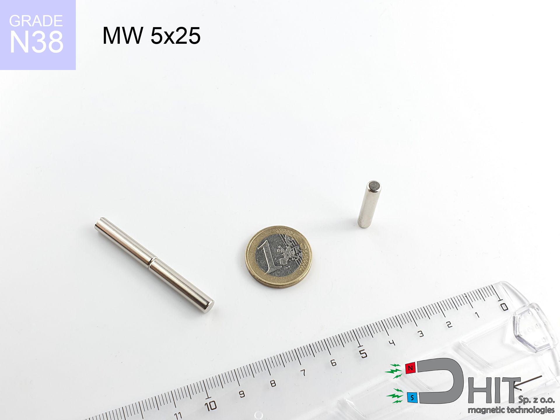
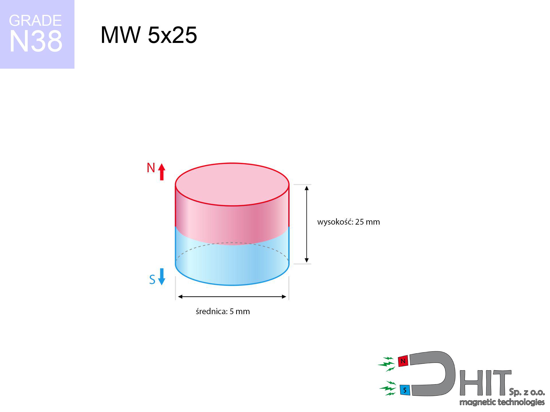
MW 5x25 / N38 - cylindrical magnet
cylindrical magnet
Catalog no 010086
GTIN/EAN: 5906301810858
Diameter Ø
5 mm [±0,1 mm]
Height
25 mm [±0,1 mm]
Weight
3.68 g
Magnetization Direction
↑ axial
Load capacity
0.45 kg / 4.41 N
Magnetic Induction
615.39 mT / 6154 Gs
Coating
[NiCuNi] Nickel
2.31 ZŁ with VAT / pcs + price for transport
1.880 ZŁ net + 23% VAT / pcs
bulk discounts:
Need more?Engineering report for this magnet
Full PDF analysis: pull and shear force, effect of distance, temperature and plate thickness, safety distances and the demagnetization curve.
Pick up the phone and ask
+48 22 499 98 98
if you prefer drop us a message using
inquiry form
our website.
Force along with appearance of a neodymium magnet can be verified with our
our magnetic calculator.
Same-day shipping for orders placed before 14:00.
Product card - MW 5x25 / N38 - cylindrical magnet
Specification / characteristics - MW 5x25 / N38 - cylindrical magnet
| properties | values |
|---|---|
| Cat. no. | 010086 |
| GTIN/EAN | 5906301810858 |
| Production/Distribution | Dhit sp. z o.o. |
| Country of origin | Poland / China / Germany |
| Customs code | 85059029 |
| Diameter Ø | 5 mm [±0,1 mm] |
| Height | 25 mm [±0,1 mm] |
| Weight | 3.68 g |
| Magnetization Direction | ↑ axial |
| Load capacity ~ ? | 0.45 kg / 4.41 N |
| Magnetic Induction ~ ? | 615.39 mT / 6154 Gs |
| Coating | [NiCuNi] Nickel |
| Manufacturing Tolerance | ±0.1 mm |
Magnetic properties of material N38
| properties | values | units |
|---|---|---|
| remenance Br [min. - max.] ? | 12.2-12.6 | kGs |
| remenance Br [min. - max.] ? | 1220-1260 | mT |
| coercivity bHc ? | 10.8-11.5 | kOe |
| coercivity bHc ? | 860-915 | kA/m |
| actual internal force iHc | ≥ 12 | kOe |
| actual internal force iHc | ≥ 955 | kA/m |
| energy density [min. - max.] ? | 36-38 | BH max MGOe |
| energy density [min. - max.] ? | 287-303 | BH max KJ/m |
| max. temperature ? | ≤ 80 | °C |
Physical properties of sintered neodymium magnets Nd2Fe14B at 20°C
| properties | values | units |
|---|---|---|
| Vickers hardness | ≥550 | Hv |
| Density | ≥7.4 | g/cm3 |
| Curie Temperature TC | 312 - 380 | °C |
| Curie Temperature TF | 593 - 716 | °F |
| Specific resistance | 150 | μΩ⋅cm |
| Bending strength | 250 | MPa |
| Compressive strength | 1000~1100 | MPa |
| Thermal expansion parallel (∥) to orientation (M) | (3-4) x 10-6 | °C-1 |
| Thermal expansion perpendicular (⊥) to orientation (M) | -(1-3) x 10-6 | °C-1 |
| Young's modulus | 1.7 x 10⁴ | kg/mm² |
Technical modeling of the assembly - report
These data constitute the result of a physical calculation. Results rely on algorithms for the material Nd2Fe14B. Operational conditions may differ from theoretical values. Please consider these data as a reference point for designers.
Table 1: Static force (pull vs distance) - characteristics
MW 5x25 / N38
| Distance (mm) | Induction (Gauss) / mT | Pull Force (kg/lbs/g/N) | Risk Status |
|---|---|---|---|
| 0 mm |
6144 Gs
614.4 mT
|
0.45 kg / 0.99 lbs
450.0 g / 4.4 N
|
safe |
| 1 mm |
3869 Gs
386.9 mT
|
0.18 kg / 0.39 lbs
178.4 g / 1.8 N
|
safe |
| 2 mm |
2300 Gs
230.0 mT
|
0.06 kg / 0.14 lbs
63.1 g / 0.6 N
|
safe |
| 3 mm |
1412 Gs
141.2 mT
|
0.02 kg / 0.05 lbs
23.8 g / 0.2 N
|
safe |
| 5 mm |
633 Gs
63.3 mT
|
0.00 kg / 0.01 lbs
4.8 g / 0.0 N
|
safe |
| 10 mm |
169 Gs
16.9 mT
|
0.00 kg / 0.00 lbs
0.3 g / 0.0 N
|
safe |
| 15 mm |
72 Gs
7.2 mT
|
0.00 kg / 0.00 lbs
0.1 g / 0.0 N
|
safe |
| 20 mm |
38 Gs
3.8 mT
|
0.00 kg / 0.00 lbs
0.0 g / 0.0 N
|
safe |
| 30 mm |
15 Gs
1.5 mT
|
0.00 kg / 0.00 lbs
0.0 g / 0.0 N
|
safe |
| 50 mm |
4 Gs
0.4 mT
|
0.00 kg / 0.00 lbs
0.0 g / 0.0 N
|
safe |
Table 2: Slippage load (wall)
MW 5x25 / N38
| Distance (mm) | Friction coefficient | Pull Force (kg/lbs/g/N) |
|---|---|---|
| 0 mm | Stal (~0.2) |
0.09 kg / 0.20 lbs
90.0 g / 0.9 N
|
| 1 mm | Stal (~0.2) |
0.04 kg / 0.08 lbs
36.0 g / 0.4 N
|
| 2 mm | Stal (~0.2) |
0.01 kg / 0.03 lbs
12.0 g / 0.1 N
|
| 3 mm | Stal (~0.2) |
0.00 kg / 0.01 lbs
4.0 g / 0.0 N
|
| 5 mm | Stal (~0.2) |
0.00 kg / 0.00 lbs
0.0 g / 0.0 N
|
| 10 mm | Stal (~0.2) |
0.00 kg / 0.00 lbs
0.0 g / 0.0 N
|
| 15 mm | Stal (~0.2) |
0.00 kg / 0.00 lbs
0.0 g / 0.0 N
|
| 20 mm | Stal (~0.2) |
0.00 kg / 0.00 lbs
0.0 g / 0.0 N
|
| 30 mm | Stal (~0.2) |
0.00 kg / 0.00 lbs
0.0 g / 0.0 N
|
| 50 mm | Stal (~0.2) |
0.00 kg / 0.00 lbs
0.0 g / 0.0 N
|
Table 3: Vertical assembly (sliding) - vertical pull
MW 5x25 / N38
| Surface type | Friction coefficient / % Mocy | Max load (kg/lbs/g/N) |
|---|---|---|
| Raw steel |
µ = 0.3
30% Nominalnej Siły
|
0.14 kg / 0.30 lbs
135.0 g / 1.3 N
|
| Painted steel (standard) |
µ = 0.2
20% Nominalnej Siły
|
0.09 kg / 0.20 lbs
90.0 g / 0.9 N
|
| Oily/slippery steel |
µ = 0.1
10% Nominalnej Siły
|
0.05 kg / 0.10 lbs
45.0 g / 0.4 N
|
| Magnet with anti-slip rubber |
µ = 0.5
50% Nominalnej Siły
|
0.23 kg / 0.50 lbs
225.0 g / 2.2 N
|
Table 4: Material efficiency (saturation) - power losses
MW 5x25 / N38
| Steel thickness (mm) | % power | Real pull force (kg/lbs/g/N) |
|---|---|---|
| 0.5 mm |
|
0.05 kg / 0.10 lbs
45.0 g / 0.4 N
|
| 1 mm |
|
0.11 kg / 0.25 lbs
112.5 g / 1.1 N
|
| 2 mm |
|
0.23 kg / 0.50 lbs
225.0 g / 2.2 N
|
| 3 mm |
|
0.34 kg / 0.74 lbs
337.5 g / 3.3 N
|
| 5 mm |
|
0.45 kg / 0.99 lbs
450.0 g / 4.4 N
|
| 10 mm |
|
0.45 kg / 0.99 lbs
450.0 g / 4.4 N
|
| 11 mm |
|
0.45 kg / 0.99 lbs
450.0 g / 4.4 N
|
| 12 mm |
|
0.45 kg / 0.99 lbs
450.0 g / 4.4 N
|
Table 5: Thermal resistance (stability) - thermal limit
MW 5x25 / N38
| Ambient temp. (°C) | Power loss | Remaining pull (kg/lbs/g/N) | Status |
|---|---|---|---|
| 20 °C | 0.0% |
0.45 kg / 0.99 lbs
450.0 g / 4.4 N
|
OK |
| 40 °C | -2.2% |
0.44 kg / 0.97 lbs
440.1 g / 4.3 N
|
OK |
| 60 °C | -4.4% |
0.43 kg / 0.95 lbs
430.2 g / 4.2 N
|
OK |
| 80 °C | -6.6% |
0.42 kg / 0.93 lbs
420.3 g / 4.1 N
|
|
| 100 °C | -28.8% |
0.32 kg / 0.71 lbs
320.4 g / 3.1 N
|
Table 6: Two magnets (attraction) - field collision
MW 5x25 / N38
| Gap (mm) | Attraction (kg/lbs) (N-S) | Shear Strength (kg/lbs/g/N) | Repulsion (kg/lbs) (N-N) |
|---|---|---|---|
| 0 mm |
4.57 kg / 10.08 lbs
6 167 Gs
|
0.69 kg / 1.51 lbs
686 g / 6.7 N
|
N/A |
| 1 mm |
2.97 kg / 6.55 lbs
9 909 Gs
|
0.45 kg / 0.98 lbs
446 g / 4.4 N
|
2.67 kg / 5.90 lbs
~0 Gs
|
| 2 mm |
1.81 kg / 3.99 lbs
7 738 Gs
|
0.27 kg / 0.60 lbs
272 g / 2.7 N
|
1.63 kg / 3.60 lbs
~0 Gs
|
| 3 mm |
1.08 kg / 2.37 lbs
5 965 Gs
|
0.16 kg / 0.36 lbs
162 g / 1.6 N
|
0.97 kg / 2.14 lbs
~0 Gs
|
| 5 mm |
0.39 kg / 0.86 lbs
3 581 Gs
|
0.06 kg / 0.13 lbs
58 g / 0.6 N
|
0.35 kg / 0.77 lbs
~0 Gs
|
| 10 mm |
0.05 kg / 0.11 lbs
1 266 Gs
|
0.01 kg / 0.02 lbs
7 g / 0.1 N
|
0.04 kg / 0.10 lbs
~0 Gs
|
| 20 mm |
0.00 kg / 0.01 lbs
339 Gs
|
0.00 kg / 0.00 lbs
1 g / 0.0 N
|
0.00 kg / 0.00 lbs
~0 Gs
|
| 50 mm |
0.00 kg / 0.00 lbs
46 Gs
|
0.00 kg / 0.00 lbs
0 g / 0.0 N
|
0.00 kg / 0.00 lbs
~0 Gs
|
| 60 mm |
0.00 kg / 0.00 lbs
30 Gs
|
0.00 kg / 0.00 lbs
0 g / 0.0 N
|
0.00 kg / 0.00 lbs
~0 Gs
|
| 70 mm |
0.00 kg / 0.00 lbs
21 Gs
|
0.00 kg / 0.00 lbs
0 g / 0.0 N
|
0.00 kg / 0.00 lbs
~0 Gs
|
| 80 mm |
0.00 kg / 0.00 lbs
15 Gs
|
0.00 kg / 0.00 lbs
0 g / 0.0 N
|
0.00 kg / 0.00 lbs
~0 Gs
|
| 90 mm |
0.00 kg / 0.00 lbs
11 Gs
|
0.00 kg / 0.00 lbs
0 g / 0.0 N
|
0.00 kg / 0.00 lbs
~0 Gs
|
| 100 mm |
0.00 kg / 0.00 lbs
9 Gs
|
0.00 kg / 0.00 lbs
0 g / 0.0 N
|
0.00 kg / 0.00 lbs
~0 Gs
|
Table 7: Hazards (electronics) - warnings
MW 5x25 / N38
| Object / Device | Limit (Gauss) / mT | Safe distance |
|---|---|---|
| Pacemaker | 5 Gs (0.5 mT) | 5.0 cm |
| Hearing aid | 10 Gs (1.0 mT) | 4.0 cm |
| Timepiece | 20 Gs (2.0 mT) | 3.0 cm |
| Phone / Smartphone | 40 Gs (4.0 mT) | 2.0 cm |
| Car key | 50 Gs (5.0 mT) | 2.0 cm |
| Payment card | 400 Gs (40.0 mT) | 1.0 cm |
| HDD hard drive | 600 Gs (60.0 mT) | 1.0 cm |
Table 8: Dynamics (cracking risk) - warning
MW 5x25 / N38
| Start from (mm) | Speed (km/h) | Energy (J) | Predicted outcome |
|---|---|---|---|
| 10 mm |
11.16 km/h
(3.10 m/s)
|
0.02 J | |
| 30 mm |
19.32 km/h
(5.37 m/s)
|
0.05 J | |
| 50 mm |
24.94 km/h
(6.93 m/s)
|
0.09 J | |
| 100 mm |
35.27 km/h
(9.80 m/s)
|
0.18 J |
Table 9: Surface protection spec
MW 5x25 / N38
| Technical parameter | Value / Description |
|---|---|
| Coating type | [NiCuNi] Nickel |
| Layer structure | Nickel - Copper - Nickel |
| Layer thickness | 10-20 µm |
| Salt spray test (SST) ? | 24 h |
| Recommended environment | Indoors only (dry) |
Table 10: Electrical data (Flux)
MW 5x25 / N38
| Parameter | Value | SI Unit / Description |
|---|---|---|
| Magnetic Flux | 1 450 Mx | 14.5 µWb |
| Pc Coefficient | 1.55 | High (Stable) |
Table 11: Physics of underwater searching
MW 5x25 / N38
| Environment | Effective steel pull | Effect |
|---|---|---|
| Air (land) | 0.45 kg | Standard |
| Water (riverbed) |
0.52 kg
(+0.07 kg buoyancy gain)
|
+14.5% |
1. Shear force
*Note: On a vertical wall, the magnet holds merely a fraction of its perpendicular strength.
2. Steel thickness impact
*Thin steel (e.g. 0.5mm PC case) drastically limits the holding force.
3. Heat tolerance
*For standard magnets, the max working temp is 80°C.
4. Demagnetization curve and operating point (B-H)
chart generated for the permeance coefficient Pc (Permeance Coefficient) = 1.55
The chart above illustrates the magnetic characteristics of the material within the second quadrant of the hysteresis loop. The solid red line represents the demagnetization curve (material potential), while the dashed blue line is the load line based on the magnet's geometry. The Pc (Permeance Coefficient), also known as the load line slope, is a dimensionless value that describes the relationship between the magnet's shape and its magnetic stability. The intersection of these two lines (the black dot) is the operating point — it determines the actual magnetic flux density generated by the magnet in this specific configuration. A higher Pc value means the magnet is more 'slender' (tall relative to its area), resulting in a higher operating point and better resistance to irreversible demagnetization caused by external fields or temperature. A value of 0.42 is relatively low (typical for flat magnets), meaning the operating point is closer to the 'knee' of the curve — caution is advised when operating at temperatures near the maximum limit to avoid strength loss.
Material specification
| iron (Fe) | 64% – 68% |
| neodymium (Nd) | 29% – 32% |
| boron (B) | 1.1% – 1.2% |
| dysprosium (Dy) | 0.5% – 2.0% |
| coating (Ni-Cu-Ni) | < 0.05% |
Ecology and recycling (GPSR)
| recyclability (EoL) | 100% |
| recycled raw materials | ~10% (pre-cons) |
| carbon footprint | low / zredukowany |
| waste code (EWC) | 16 02 16 |
View also offers

![SM 25x375 [2xM8] / N42 - magnetic separator](https://cdn3.dhit.pl/graphics/products/sm-25x375-2xm8-feg.jpg "SM 25x375 [2xM8] / N42 - magnetic separator")

![UMH 16x5x32 [M4] / N38 - magnetic holder with hook](https://cdn3.dhit.pl/graphics/products/umh-16x5x32-m4-lak.jpg "UMH 16x5x32 [M4] / N38 - magnetic holder with hook")
Advantages and disadvantages of Nd2Fe14B magnets.
Strengths
- They do not lose power, even after nearly 10 years – the reduction in strength is only ~1% (theoretically),
- Magnets perfectly protect themselves against loss of magnetization caused by ambient magnetic noise,
- A magnet with a metallic nickel surface has better aesthetics,
- Magnets have maximum magnetic induction on the working surface,
- Neodymium magnets are characterized by very high magnetic induction on the magnet surface and are able to act (depending on the form) even at a temperature of 230°C or more...
- Possibility of detailed modeling and optimizing to defined needs,
- Key role in modern technologies – they serve a role in data components, electric motors, precision medical tools, as well as multitasking production systems.
- Relatively small size with high pulling force – neodymium magnets offer impressive pulling force in tiny dimensions, which makes them useful in miniature devices
Cons
- To avoid cracks under impact, we recommend using special steel holders. Such a solution secures the magnet and simultaneously improves its durability.
- Neodymium magnets demagnetize when exposed to high temperatures. After reaching 80°C, many of them experience permanent drop of strength (a factor is the shape as well as dimensions of the magnet). We offer magnets specially adapted to work at temperatures up to 230°C marked [AH], which are very resistant to heat
- Magnets exposed to a humid environment can corrode. Therefore during using outdoors, we suggest using water-impermeable magnets made of rubber, plastic or other material resistant to moisture
- We suggest a housing - magnetic mechanism, due to difficulties in realizing nuts inside the magnet and complex forms.
- Potential hazard to health – tiny shards of magnets can be dangerous, when accidentally swallowed, which is particularly important in the aspect of protecting the youngest. Additionally, small elements of these magnets are able to complicate diagnosis medical after entering the body.
- Due to expensive raw materials, their price exceeds standard values,
Pull force analysis
Magnetic strength at its maximum – what contributes to it?
- using a plate made of high-permeability steel, functioning as a ideal flux conductor
- whose thickness reaches at least 10 mm
- characterized by lack of roughness
- under conditions of ideal adhesion (metal-to-metal)
- under perpendicular force direction (90-degree angle)
- in temp. approx. 20°C
Lifting capacity in real conditions – factors
- Distance (between the magnet and the metal), since even a tiny distance (e.g. 0.5 mm) results in a drastic drop in force by up to 50% (this also applies to paint, corrosion or debris).
- Pull-off angle – remember that the magnet holds strongest perpendicularly. Under sliding down, the capacity drops drastically, often to levels of 20-30% of the nominal value.
- Element thickness – for full efficiency, the steel must be adequately massive. Paper-thin metal restricts the attraction force (the magnet "punches through" it).
- Steel type – low-carbon steel attracts best. Alloy steels reduce magnetic properties and lifting capacity.
- Surface condition – ground elements ensure maximum contact, which increases force. Uneven metal weaken the grip.
- Thermal environment – heating the magnet results in weakening of force. It is worth remembering the thermal limit for a given model.
Holding force was tested on a smooth steel plate of 20 mm thickness, when the force acted perpendicularly, in contrast under parallel forces the lifting capacity is smaller. Moreover, even a slight gap between the magnet and the plate lowers the load capacity.
Safety rules for work with NdFeB magnets
Skin irritation risks
Certain individuals experience a contact allergy to nickel, which is the common plating for NdFeB magnets. Frequent touching can result in skin redness. It is best to wear protective gloves.
Choking Hazard
Neodymium magnets are not toys. Eating multiple magnets can lead to them connecting inside the digestive tract, which constitutes a severe health hazard and necessitates immediate surgery.
Safe operation
Handle magnets consciously. Their huge power can shock even experienced users. Plan your moves and respect their power.
Mechanical processing
Powder produced during grinding of magnets is self-igniting. Avoid drilling into magnets unless you are an expert.
Pacemakers
Life threat: Neodymium magnets can turn off heart devices and defibrillators. Do not approach if you have electronic implants.
Protective goggles
Protect your eyes. Magnets can explode upon uncontrolled impact, ejecting shards into the air. Eye protection is mandatory.
Electronic devices
Avoid bringing magnets near a purse, computer, or TV. The magnetic field can irreversibly ruin these devices and erase data from cards.
Magnetic interference
An intense magnetic field negatively affects the functioning of magnetometers in smartphones and GPS navigation. Maintain magnets close to a smartphone to avoid damaging the sensors.
Operating temperature
Regular neodymium magnets (grade N) lose magnetization when the temperature exceeds 80°C. Damage is permanent.
Crushing risk
Risk of injury: The pulling power is so great that it can cause blood blisters, pinching, and broken bones. Protective gloves are recommended.
Tabela kosztu i czasu dostawy
Płatność przed wysyłką:

GLS kurier
Przesyłka będzie u Ciebie za 2-3 dni
14.99 ZŁ

InPost Paczkomaty 24/7
Przesyłka będzie u Ciebie za 1-2 dni
12.30 ZŁ
Płatność przy odbiorze (pobranie):
GLS kurier
Przesyłka będzie u Ciebie za 1-2 dni
23.00 ZŁ
Rate the product
Your rating