

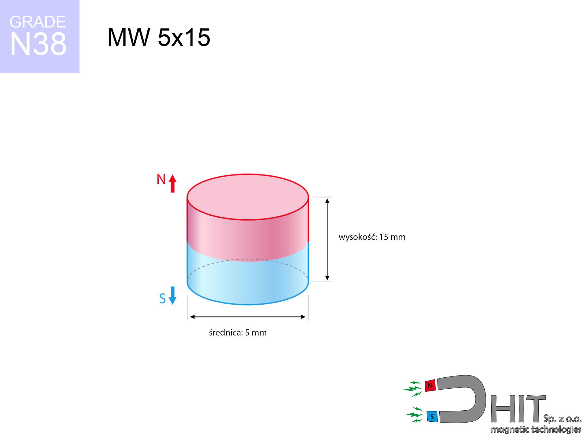
MW 5x15 / N38 - cylindrical magnet
cylindrical magnet
Catalog no 010084
GTIN/EAN: 5906301810834
Diameter Ø
5 mm [±0,1 mm]
Height
15 mm [±0,1 mm]
Weight
2.21 g
Magnetization Direction
↑ axial
Load capacity
0.48 kg / 4.68 N
Magnetic Induction
610.03 mT / 6100 Gs
Coating
[NiCuNi] Nickel
1.107 ZŁ with VAT / pcs + price for transport
0.900 ZŁ net + 23% VAT / pcs
bulk discounts:
Need more?
Pick up the phone and ask
+48 22 499 98 98
if you prefer get in touch through
request form
our website.
Force as well as appearance of a neodymium magnet can be verified on our
modular calculator.
Same-day processing for orders placed before 14:00.
Product card - MW 5x15 / N38 - cylindrical magnet
Specification / characteristics - MW 5x15 / N38 - cylindrical magnet
| properties | values |
|---|---|
| Cat. no. | 010084 |
| GTIN/EAN | 5906301810834 |
| Production/Distribution | Dhit sp. z o.o. |
| Country of origin | Poland / China / Germany |
| Customs code | 85059029 |
| Diameter Ø | 5 mm [±0,1 mm] |
| Height | 15 mm [±0,1 mm] |
| Weight | 2.21 g |
| Magnetization Direction | ↑ axial |
| Load capacity ~ ? | 0.48 kg / 4.68 N |
| Magnetic Induction ~ ? | 610.03 mT / 6100 Gs |
| Coating | [NiCuNi] Nickel |
| Manufacturing Tolerance | ±0.1 mm |
Magnetic properties of material N38
| properties | values | units |
|---|---|---|
| remenance Br [min. - max.] ? | 12.2-12.6 | kGs |
| remenance Br [min. - max.] ? | 1220-1260 | mT |
| coercivity bHc ? | 10.8-11.5 | kOe |
| coercivity bHc ? | 860-915 | kA/m |
| actual internal force iHc | ≥ 12 | kOe |
| actual internal force iHc | ≥ 955 | kA/m |
| energy density [min. - max.] ? | 36-38 | BH max MGOe |
| energy density [min. - max.] ? | 287-303 | BH max KJ/m |
| max. temperature ? | ≤ 80 | °C |
Physical properties of sintered neodymium magnets Nd2Fe14B at 20°C
| properties | values | units |
|---|---|---|
| Vickers hardness | ≥550 | Hv |
| Density | ≥7.4 | g/cm3 |
| Curie Temperature TC | 312 - 380 | °C |
| Curie Temperature TF | 593 - 716 | °F |
| Specific resistance | 150 | μΩ⋅cm |
| Bending strength | 250 | MPa |
| Compressive strength | 1000~1100 | MPa |
| Thermal expansion parallel (∥) to orientation (M) | (3-4) x 10-6 | °C-1 |
| Thermal expansion perpendicular (⊥) to orientation (M) | -(1-3) x 10-6 | °C-1 |
| Young's modulus | 1.7 x 10⁴ | kg/mm² |
Technical simulation of the product - technical parameters
These values are the direct effect of a physical calculation. Values were calculated on models for the material Nd2Fe14B. Real-world performance may deviate from the simulation results. Treat these calculations as a reference point for designers.
Table 1: Static force (force vs gap) - characteristics
MW 5x15 / N38
| Distance (mm) | Induction (Gauss) / mT | Pull Force (kg/lbs/g/N) | Risk Status |
|---|---|---|---|
| 0 mm |
6091 Gs
609.1 mT
|
0.48 kg / 1.06 pounds
480.0 g / 4.7 N
|
weak grip |
| 1 mm |
3823 Gs
382.3 mT
|
0.19 kg / 0.42 pounds
189.1 g / 1.9 N
|
weak grip |
| 2 mm |
2261 Gs
226.1 mT
|
0.07 kg / 0.15 pounds
66.1 g / 0.6 N
|
weak grip |
| 3 mm |
1378 Gs
137.8 mT
|
0.02 kg / 0.05 pounds
24.6 g / 0.2 N
|
weak grip |
| 5 mm |
607 Gs
60.7 mT
|
0.00 kg / 0.01 pounds
4.8 g / 0.0 N
|
weak grip |
| 10 mm |
154 Gs
15.4 mT
|
0.00 kg / 0.00 pounds
0.3 g / 0.0 N
|
weak grip |
| 15 mm |
63 Gs
6.3 mT
|
0.00 kg / 0.00 pounds
0.1 g / 0.0 N
|
weak grip |
| 20 mm |
32 Gs
3.2 mT
|
0.00 kg / 0.00 pounds
0.0 g / 0.0 N
|
weak grip |
| 30 mm |
12 Gs
1.2 mT
|
0.00 kg / 0.00 pounds
0.0 g / 0.0 N
|
weak grip |
| 50 mm |
3 Gs
0.3 mT
|
0.00 kg / 0.00 pounds
0.0 g / 0.0 N
|
weak grip |
Table 2: Slippage hold (vertical surface)
MW 5x15 / N38
| Distance (mm) | Friction coefficient | Pull Force (kg/lbs/g/N) |
|---|---|---|
| 0 mm | Stal (~0.2) |
0.10 kg / 0.21 pounds
96.0 g / 0.9 N
|
| 1 mm | Stal (~0.2) |
0.04 kg / 0.08 pounds
38.0 g / 0.4 N
|
| 2 mm | Stal (~0.2) |
0.01 kg / 0.03 pounds
14.0 g / 0.1 N
|
| 3 mm | Stal (~0.2) |
0.00 kg / 0.01 pounds
4.0 g / 0.0 N
|
| 5 mm | Stal (~0.2) |
0.00 kg / 0.00 pounds
0.0 g / 0.0 N
|
| 10 mm | Stal (~0.2) |
0.00 kg / 0.00 pounds
0.0 g / 0.0 N
|
| 15 mm | Stal (~0.2) |
0.00 kg / 0.00 pounds
0.0 g / 0.0 N
|
| 20 mm | Stal (~0.2) |
0.00 kg / 0.00 pounds
0.0 g / 0.0 N
|
| 30 mm | Stal (~0.2) |
0.00 kg / 0.00 pounds
0.0 g / 0.0 N
|
| 50 mm | Stal (~0.2) |
0.00 kg / 0.00 pounds
0.0 g / 0.0 N
|
Table 3: Wall mounting (sliding) - vertical pull
MW 5x15 / N38
| Surface type | Friction coefficient / % Mocy | Max load (kg/lbs/g/N) |
|---|---|---|
| Raw steel |
µ = 0.3
30% Nominalnej Siły
|
0.14 kg / 0.32 pounds
144.0 g / 1.4 N
|
| Painted steel (standard) |
µ = 0.2
20% Nominalnej Siły
|
0.10 kg / 0.21 pounds
96.0 g / 0.9 N
|
| Oily/slippery steel |
µ = 0.1
10% Nominalnej Siły
|
0.05 kg / 0.11 pounds
48.0 g / 0.5 N
|
| Magnet with anti-slip rubber |
µ = 0.5
50% Nominalnej Siły
|
0.24 kg / 0.53 pounds
240.0 g / 2.4 N
|
Table 4: Material efficiency (substrate influence) - sheet metal selection
MW 5x15 / N38
| Steel thickness (mm) | % power | Real pull force (kg/lbs/g/N) |
|---|---|---|
| 0.5 mm |
|
0.05 kg / 0.11 pounds
48.0 g / 0.5 N
|
| 1 mm |
|
0.12 kg / 0.26 pounds
120.0 g / 1.2 N
|
| 2 mm |
|
0.24 kg / 0.53 pounds
240.0 g / 2.4 N
|
| 3 mm |
|
0.36 kg / 0.79 pounds
360.0 g / 3.5 N
|
| 5 mm |
|
0.48 kg / 1.06 pounds
480.0 g / 4.7 N
|
| 10 mm |
|
0.48 kg / 1.06 pounds
480.0 g / 4.7 N
|
| 11 mm |
|
0.48 kg / 1.06 pounds
480.0 g / 4.7 N
|
| 12 mm |
|
0.48 kg / 1.06 pounds
480.0 g / 4.7 N
|
Table 5: Thermal stability (material behavior) - power drop
MW 5x15 / N38
| Ambient temp. (°C) | Power loss | Remaining pull (kg/lbs/g/N) | Status |
|---|---|---|---|
| 20 °C | 0.0% |
0.48 kg / 1.06 pounds
480.0 g / 4.7 N
|
OK |
| 40 °C | -2.2% |
0.47 kg / 1.03 pounds
469.4 g / 4.6 N
|
OK |
| 60 °C | -4.4% |
0.46 kg / 1.01 pounds
458.9 g / 4.5 N
|
OK |
| 80 °C | -6.6% |
0.45 kg / 0.99 pounds
448.3 g / 4.4 N
|
|
| 100 °C | -28.8% |
0.34 kg / 0.75 pounds
341.8 g / 3.4 N
|
Table 6: Magnet-Magnet interaction (repulsion) - field collision
MW 5x15 / N38
| Gap (mm) | Attraction (kg/lbs) (N-S) | Sliding Force (kg/lbs/g/N) | Repulsion (kg/lbs) (N-N) |
|---|---|---|---|
| 0 mm |
4.49 kg / 9.90 pounds
6 154 Gs
|
0.67 kg / 1.49 pounds
674 g / 6.6 N
|
N/A |
| 1 mm |
2.91 kg / 6.42 pounds
9 810 Gs
|
0.44 kg / 0.96 pounds
437 g / 4.3 N
|
2.62 kg / 5.78 pounds
~0 Gs
|
| 2 mm |
1.77 kg / 3.90 pounds
7 646 Gs
|
0.27 kg / 0.59 pounds
265 g / 2.6 N
|
1.59 kg / 3.51 pounds
~0 Gs
|
| 3 mm |
1.05 kg / 2.31 pounds
5 880 Gs
|
0.16 kg / 0.35 pounds
157 g / 1.5 N
|
0.94 kg / 2.08 pounds
~0 Gs
|
| 5 mm |
0.37 kg / 0.82 pounds
3 507 Gs
|
0.06 kg / 0.12 pounds
56 g / 0.5 N
|
0.34 kg / 0.74 pounds
~0 Gs
|
| 10 mm |
0.04 kg / 0.10 pounds
1 213 Gs
|
0.01 kg / 0.01 pounds
7 g / 0.1 N
|
0.04 kg / 0.09 pounds
~0 Gs
|
| 20 mm |
0.00 kg / 0.01 pounds
309 Gs
|
0.00 kg / 0.00 pounds
0 g / 0.0 N
|
0.00 kg / 0.00 pounds
~0 Gs
|
| 50 mm |
0.00 kg / 0.00 pounds
37 Gs
|
0.00 kg / 0.00 pounds
0 g / 0.0 N
|
0.00 kg / 0.00 pounds
~0 Gs
|
| 60 mm |
0.00 kg / 0.00 pounds
24 Gs
|
0.00 kg / 0.00 pounds
0 g / 0.0 N
|
0.00 kg / 0.00 pounds
~0 Gs
|
| 70 mm |
0.00 kg / 0.00 pounds
16 Gs
|
0.00 kg / 0.00 pounds
0 g / 0.0 N
|
0.00 kg / 0.00 pounds
~0 Gs
|
| 80 mm |
0.00 kg / 0.00 pounds
11 Gs
|
0.00 kg / 0.00 pounds
0 g / 0.0 N
|
0.00 kg / 0.00 pounds
~0 Gs
|
| 90 mm |
0.00 kg / 0.00 pounds
8 Gs
|
0.00 kg / 0.00 pounds
0 g / 0.0 N
|
0.00 kg / 0.00 pounds
~0 Gs
|
| 100 mm |
0.00 kg / 0.00 pounds
6 Gs
|
0.00 kg / 0.00 pounds
0 g / 0.0 N
|
0.00 kg / 0.00 pounds
~0 Gs
|
Table 7: Safety (HSE) (electronics) - warnings
MW 5x15 / N38
| Object / Device | Limit (Gauss) / mT | Safe distance |
|---|---|---|
| Pacemaker | 5 Gs (0.5 mT) | 4.5 cm |
| Hearing aid | 10 Gs (1.0 mT) | 3.5 cm |
| Mechanical watch | 20 Gs (2.0 mT) | 2.5 cm |
| Mobile device | 40 Gs (4.0 mT) | 2.0 cm |
| Remote | 50 Gs (5.0 mT) | 2.0 cm |
| Payment card | 400 Gs (40.0 mT) | 1.0 cm |
| HDD hard drive | 600 Gs (60.0 mT) | 1.0 cm |
Table 8: Collisions (kinetic energy) - warning
MW 5x15 / N38
| Start from (mm) | Speed (km/h) | Energy (J) | Predicted outcome |
|---|---|---|---|
| 10 mm |
14.87 km/h
(4.13 m/s)
|
0.02 J | |
| 30 mm |
25.74 km/h
(7.15 m/s)
|
0.06 J | |
| 50 mm |
33.23 km/h
(9.23 m/s)
|
0.09 J | |
| 100 mm |
47.00 km/h
(13.06 m/s)
|
0.19 J |
Table 9: Surface protection spec
MW 5x15 / N38
| Technical parameter | Value / Description |
|---|---|
| Coating type | [NiCuNi] Nickel |
| Layer structure | Nickel - Copper - Nickel |
| Layer thickness | 10-20 µm |
| Salt spray test (SST) ? | 24 h |
| Recommended environment | Indoors only (dry) |
Table 10: Electrical data (Pc)
MW 5x15 / N38
| Parameter | Value | SI Unit / Description |
|---|---|---|
| Magnetic Flux | 1 382 Mx | 13.8 µWb |
| Pc Coefficient | 1.38 | High (Stable) |
Table 11: Underwater work (magnet fishing)
MW 5x15 / N38
| Environment | Effective steel pull | Effect |
|---|---|---|
| Air (land) | 0.48 kg | Standard |
| Water (riverbed) |
0.55 kg
(+0.07 kg buoyancy gain)
|
+14.5% |
1. Shear force
*Note: On a vertical wall, the magnet holds merely ~20% of its max power.
2. Steel saturation
*Thin metal sheet (e.g. computer case) drastically weakens the holding force.
3. Thermal stability
*For N38 grade, the safety limit is 80°C.
4. Demagnetization curve and operating point (B-H)
chart generated for the permeance coefficient Pc (Permeance Coefficient) = 1.38
The chart above illustrates the magnetic characteristics of the material within the second quadrant of the hysteresis loop. The solid red line represents the demagnetization curve (material potential), while the dashed blue line is the load line based on the magnet's geometry. The Pc (Permeance Coefficient), also known as the load line slope, is a dimensionless value that describes the relationship between the magnet's shape and its magnetic stability. The intersection of these two lines (the black dot) is the operating point — it determines the actual magnetic flux density generated by the magnet in this specific configuration. A higher Pc value means the magnet is more 'slender' (tall relative to its area), resulting in a higher operating point and better resistance to irreversible demagnetization caused by external fields or temperature. A value of 0.42 is relatively low (typical for flat magnets), meaning the operating point is closer to the 'knee' of the curve — caution is advised when operating at temperatures near the maximum limit to avoid strength loss.
Material specification
| iron (Fe) | 64% – 68% |
| neodymium (Nd) | 29% – 32% |
| boron (B) | 1.1% – 1.2% |
| dysprosium (Dy) | 0.5% – 2.0% |
| coating (Ni-Cu-Ni) | < 0.05% |
Sustainability
| recyclability (EoL) | 100% |
| recycled raw materials | ~10% (pre-cons) |
| carbon footprint | low / zredukowany |
| waste code (EWC) | 16 02 16 |
Check out also deals


![BM 650x180x70 [4x M8] - magnetic beam](https://cdn3.dhit.pl/graphics/products/bm-650x180x70-4x-m8-laj.jpg "BM 650x180x70 [4x M8] - magnetic beam")
Advantages as well as disadvantages of rare earth magnets.
Strengths
- They have constant strength, and over nearly 10 years their performance decreases symbolically – ~1% (according to theory),
- Neodymium magnets prove to be remarkably resistant to loss of magnetic properties caused by external interference,
- The use of an aesthetic layer of noble metals (nickel, gold, silver) causes the element to look better,
- The surface of neodymium magnets generates a intense magnetic field – this is one of their assets,
- Thanks to resistance to high temperature, they are able to function (depending on the shape) even at temperatures up to 230°C and higher...
- Thanks to flexibility in shaping and the ability to customize to unusual requirements,
- Significant place in high-tech industry – they are commonly used in hard drives, electric drive systems, advanced medical instruments, also multitasking production systems.
- Compactness – despite small sizes they offer powerful magnetic field, making them ideal for precision applications
Cons
- At strong impacts they can break, therefore we advise placing them in strong housings. A metal housing provides additional protection against damage and increases the magnet's durability.
- Neodymium magnets decrease their power under the influence of heating. As soon as 80°C is exceeded, many of them start losing their force. Therefore, we recommend our special magnets marked [AH], which maintain stability even at temperatures up to 230°C
- When exposed to humidity, magnets start to rust. For applications outside, it is recommended to use protective magnets, such as those in rubber or plastics, which secure oxidation as well as corrosion.
- We recommend casing - magnetic mechanism, due to difficulties in realizing threads inside the magnet and complicated forms.
- Potential hazard resulting from small fragments of magnets can be dangerous, if swallowed, which gains importance in the context of child safety. Additionally, tiny parts of these products are able to complicate diagnosis medical after entering the body.
- High unit price – neodymium magnets cost more than other types of magnets (e.g. ferrite), which hinders application in large quantities
Pull force analysis
Maximum lifting capacity of the magnet – what contributes to it?
- using a base made of low-carbon steel, functioning as a circuit closing element
- possessing a thickness of min. 10 mm to ensure full flux closure
- characterized by even structure
- with direct contact (no impurities)
- for force acting at a right angle (in the magnet axis)
- at temperature room level
Key elements affecting lifting force
- Space between magnet and steel – even a fraction of a millimeter of distance (caused e.g. by veneer or unevenness) diminishes the magnet efficiency, often by half at just 0.5 mm.
- Direction of force – maximum parameter is available only during pulling at a 90° angle. The force required to slide of the magnet along the plate is typically many times lower (approx. 1/5 of the lifting capacity).
- Steel thickness – too thin steel causes magnetic saturation, causing part of the flux to be lost into the air.
- Metal type – different alloys reacts the same. Alloy additives worsen the attraction effect.
- Plate texture – smooth surfaces guarantee perfect abutment, which increases field saturation. Uneven metal reduce efficiency.
- Temperature influence – high temperature reduces pulling force. Exceeding the limit temperature can permanently damage the magnet.
Holding force was measured on a smooth steel plate of 20 mm thickness, when a perpendicular force was applied, whereas under shearing force the lifting capacity is smaller. Moreover, even a slight gap between the magnet’s surface and the plate lowers the load capacity.
Safe handling of neodymium magnets
Implant safety
Warning for patients: Powerful magnets disrupt electronics. Maintain at least 30 cm distance or ask another person to work with the magnets.
This is not a toy
These products are not intended for children. Swallowing multiple magnets can lead to them pinching intestinal walls, which poses a severe health hazard and necessitates immediate surgery.
Threat to electronics
Powerful magnetic fields can erase data on credit cards, hard drives, and other magnetic media. Maintain a gap of at least 10 cm.
Permanent damage
Keep cool. Neodymium magnets are sensitive to heat. If you need resistance above 80°C, ask us about special high-temperature series (H, SH, UH).
Crushing force
Mind your fingers. Two large magnets will join immediately with a force of several hundred kilograms, destroying anything in their path. Be careful!
Eye protection
Despite the nickel coating, neodymium is brittle and not impact-resistant. Do not hit, as the magnet may shatter into sharp, dangerous pieces.
Respect the power
Exercise caution. Rare earth magnets act from a long distance and connect with massive power, often quicker than you can move away.
Sensitization to coating
A percentage of the population have a contact allergy to nickel, which is the standard coating for neodymium magnets. Frequent touching can result in a rash. We recommend wear safety gloves.
Precision electronics
GPS units and mobile phones are highly sensitive to magnetic fields. Close proximity with a powerful NdFeB magnet can decalibrate the internal compass in your phone.
Fire risk
Fire warning: Rare earth powder is highly flammable. Avoid machining magnets in home conditions as this risks ignition.
Tabela kosztu i czasu dostawy
Płatność przed wysyłką:

GLS kurier
Przesyłka będzie u Ciebie za 2-3 dni
14.99 ZŁ

InPost Paczkomaty 24/7
Przesyłka będzie u Ciebie za 1-2 dni
12.30 ZŁ
Płatność przy odbiorze (pobranie):
GLS kurier
Przesyłka będzie u Ciebie za 1-2 dni
23.00 ZŁ
Rate the product
Your rating