
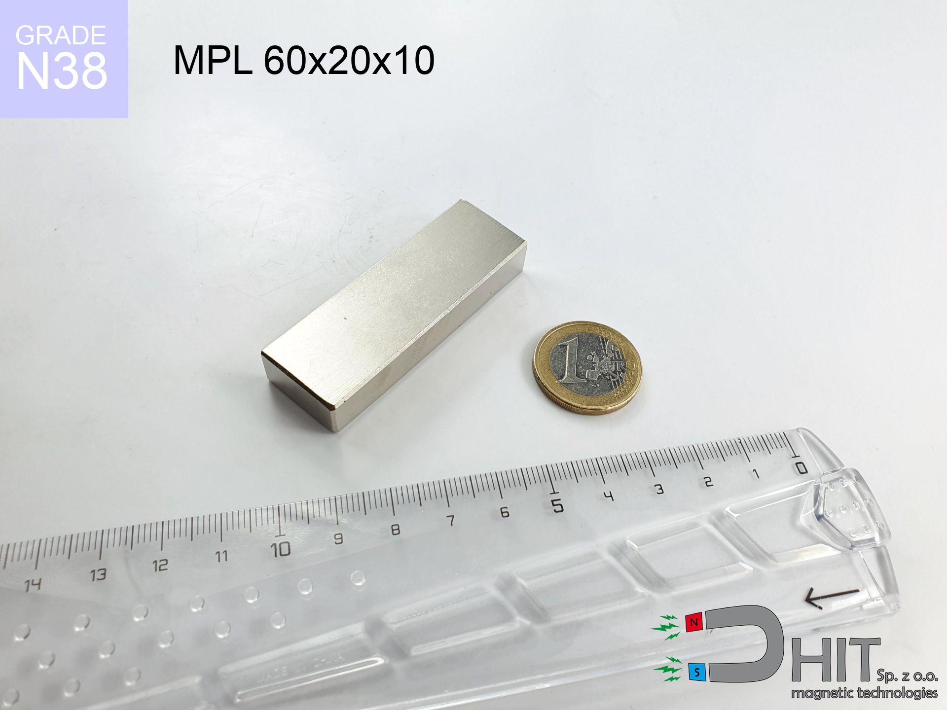
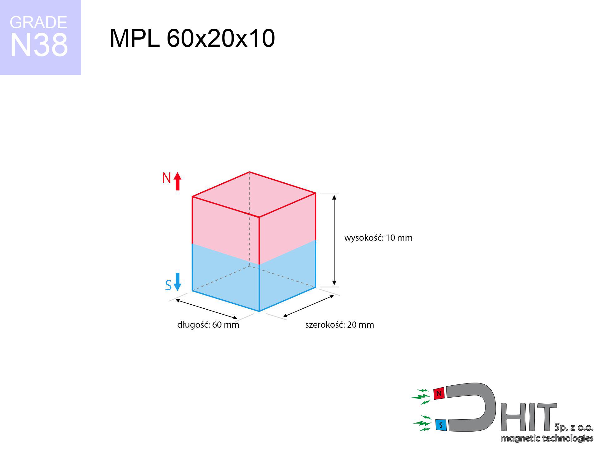
MPL 60x20x10 / N38 - lamellar magnet
lamellar magnet
Catalog no 020174
GTIN/EAN: 5906301811800
length
60 mm [±0,1 mm]
Width
20 mm [±0,1 mm]
Height
10 mm [±0,1 mm]
Weight
90 g
Magnetization Direction
↑ axial
Load capacity
35.61 kg / 349.34 N
Magnetic Induction
329.64 mT / 3296 Gs
Coating
[NiCuNi] Nickel
68.27 ZŁ with VAT / pcs + price for transport
55.50 ZŁ net + 23% VAT / pcs
bulk discounts:
Need more?
Call us
+48 22 499 98 98
otherwise get in touch via
form
the contact section.
Specifications and form of neodymium magnets can be analyzed with our
force calculator.
Orders placed before 14:00 will be shipped the same business day.
Technical parameters - MPL 60x20x10 / N38 - lamellar magnet
Specification / characteristics - MPL 60x20x10 / N38 - lamellar magnet
| properties | values |
|---|---|
| Cat. no. | 020174 |
| GTIN/EAN | 5906301811800 |
| Production/Distribution | Dhit sp. z o.o. |
| Country of origin | Poland / China / Germany |
| Customs code | 85059029 |
| length | 60 mm [±0,1 mm] |
| Width | 20 mm [±0,1 mm] |
| Height | 10 mm [±0,1 mm] |
| Weight | 90 g |
| Magnetization Direction | ↑ axial |
| Load capacity ~ ? | 35.61 kg / 349.34 N |
| Magnetic Induction ~ ? | 329.64 mT / 3296 Gs |
| Coating | [NiCuNi] Nickel |
| Manufacturing Tolerance | ±0.1 mm |
Magnetic properties of material N38
| properties | values | units |
|---|---|---|
| remenance Br [min. - max.] ? | 12.2-12.6 | kGs |
| remenance Br [min. - max.] ? | 1220-1260 | mT |
| coercivity bHc ? | 10.8-11.5 | kOe |
| coercivity bHc ? | 860-915 | kA/m |
| actual internal force iHc | ≥ 12 | kOe |
| actual internal force iHc | ≥ 955 | kA/m |
| energy density [min. - max.] ? | 36-38 | BH max MGOe |
| energy density [min. - max.] ? | 287-303 | BH max KJ/m |
| max. temperature ? | ≤ 80 | °C |
Physical properties of sintered neodymium magnets Nd2Fe14B at 20°C
| properties | values | units |
|---|---|---|
| Vickers hardness | ≥550 | Hv |
| Density | ≥7.4 | g/cm3 |
| Curie Temperature TC | 312 - 380 | °C |
| Curie Temperature TF | 593 - 716 | °F |
| Specific resistance | 150 | μΩ⋅cm |
| Bending strength | 250 | MPa |
| Compressive strength | 1000~1100 | MPa |
| Thermal expansion parallel (∥) to orientation (M) | (3-4) x 10-6 | °C-1 |
| Thermal expansion perpendicular (⊥) to orientation (M) | -(1-3) x 10-6 | °C-1 |
| Young's modulus | 1.7 x 10⁴ | kg/mm² |
Technical simulation of the product - technical parameters
Presented data represent the result of a physical calculation. Values are based on models for the class Nd2Fe14B. Operational conditions may differ from theoretical values. Use these calculations as a reference point for designers.
Table 1: Static force (force vs gap) - power drop
MPL 60x20x10 / N38
| Distance (mm) | Induction (Gauss) / mT | Pull Force (kg/lbs/g/N) | Risk Status |
|---|---|---|---|
| 0 mm |
3296 Gs
329.6 mT
|
35.61 kg / 78.51 LBS
35610.0 g / 349.3 N
|
crushing |
| 1 mm |
3087 Gs
308.7 mT
|
31.25 kg / 68.89 LBS
31248.2 g / 306.5 N
|
crushing |
| 2 mm |
2866 Gs
286.6 mT
|
26.93 kg / 59.37 LBS
26929.3 g / 264.2 N
|
crushing |
| 3 mm |
2643 Gs
264.3 mT
|
22.90 kg / 50.48 LBS
22895.5 g / 224.6 N
|
crushing |
| 5 mm |
2216 Gs
221.6 mT
|
16.10 kg / 35.50 LBS
16103.3 g / 158.0 N
|
crushing |
| 10 mm |
1397 Gs
139.7 mT
|
6.40 kg / 14.11 LBS
6402.3 g / 62.8 N
|
medium risk |
| 15 mm |
907 Gs
90.7 mT
|
2.70 kg / 5.95 LBS
2697.7 g / 26.5 N
|
medium risk |
| 20 mm |
615 Gs
61.5 mT
|
1.24 kg / 2.73 LBS
1239.2 g / 12.2 N
|
low risk |
| 30 mm |
314 Gs
31.4 mT
|
0.32 kg / 0.71 LBS
322.6 g / 3.2 N
|
low risk |
| 50 mm |
108 Gs
10.8 mT
|
0.04 kg / 0.09 LBS
38.6 g / 0.4 N
|
low risk |
Table 2: Sliding force (vertical surface)
MPL 60x20x10 / N38
| Distance (mm) | Friction coefficient | Pull Force (kg/lbs/g/N) |
|---|---|---|
| 0 mm | Stal (~0.2) |
7.12 kg / 15.70 LBS
7122.0 g / 69.9 N
|
| 1 mm | Stal (~0.2) |
6.25 kg / 13.78 LBS
6250.0 g / 61.3 N
|
| 2 mm | Stal (~0.2) |
5.39 kg / 11.87 LBS
5386.0 g / 52.8 N
|
| 3 mm | Stal (~0.2) |
4.58 kg / 10.10 LBS
4580.0 g / 44.9 N
|
| 5 mm | Stal (~0.2) |
3.22 kg / 7.10 LBS
3220.0 g / 31.6 N
|
| 10 mm | Stal (~0.2) |
1.28 kg / 2.82 LBS
1280.0 g / 12.6 N
|
| 15 mm | Stal (~0.2) |
0.54 kg / 1.19 LBS
540.0 g / 5.3 N
|
| 20 mm | Stal (~0.2) |
0.25 kg / 0.55 LBS
248.0 g / 2.4 N
|
| 30 mm | Stal (~0.2) |
0.06 kg / 0.14 LBS
64.0 g / 0.6 N
|
| 50 mm | Stal (~0.2) |
0.01 kg / 0.02 LBS
8.0 g / 0.1 N
|
Table 3: Vertical assembly (shearing) - vertical pull
MPL 60x20x10 / N38
| Surface type | Friction coefficient / % Mocy | Max load (kg/lbs/g/N) |
|---|---|---|
| Raw steel |
µ = 0.3
30% Nominalnej Siły
|
10.68 kg / 23.55 LBS
10683.0 g / 104.8 N
|
| Painted steel (standard) |
µ = 0.2
20% Nominalnej Siły
|
7.12 kg / 15.70 LBS
7122.0 g / 69.9 N
|
| Oily/slippery steel |
µ = 0.1
10% Nominalnej Siły
|
3.56 kg / 7.85 LBS
3561.0 g / 34.9 N
|
| Magnet with anti-slip rubber |
µ = 0.5
50% Nominalnej Siły
|
17.81 kg / 39.25 LBS
17805.0 g / 174.7 N
|
Table 4: Steel thickness (substrate influence) - sheet metal selection
MPL 60x20x10 / N38
| Steel thickness (mm) | % power | Real pull force (kg/lbs/g/N) |
|---|---|---|
| 0.5 mm |
|
1.78 kg / 3.93 LBS
1780.5 g / 17.5 N
|
| 1 mm |
|
4.45 kg / 9.81 LBS
4451.3 g / 43.7 N
|
| 2 mm |
|
8.90 kg / 19.63 LBS
8902.5 g / 87.3 N
|
| 3 mm |
|
13.35 kg / 29.44 LBS
13353.8 g / 131.0 N
|
| 5 mm |
|
22.26 kg / 49.07 LBS
22256.3 g / 218.3 N
|
| 10 mm |
|
35.61 kg / 78.51 LBS
35610.0 g / 349.3 N
|
| 11 mm |
|
35.61 kg / 78.51 LBS
35610.0 g / 349.3 N
|
| 12 mm |
|
35.61 kg / 78.51 LBS
35610.0 g / 349.3 N
|
Table 5: Working in heat (material behavior) - thermal limit
MPL 60x20x10 / N38
| Ambient temp. (°C) | Power loss | Remaining pull (kg/lbs/g/N) | Status |
|---|---|---|---|
| 20 °C | 0.0% |
35.61 kg / 78.51 LBS
35610.0 g / 349.3 N
|
OK |
| 40 °C | -2.2% |
34.83 kg / 76.78 LBS
34826.6 g / 341.6 N
|
OK |
| 60 °C | -4.4% |
34.04 kg / 75.05 LBS
34043.2 g / 334.0 N
|
|
| 80 °C | -6.6% |
33.26 kg / 73.33 LBS
33259.7 g / 326.3 N
|
|
| 100 °C | -28.8% |
25.35 kg / 55.90 LBS
25354.3 g / 248.7 N
|
Table 6: Two magnets (attraction) - field collision
MPL 60x20x10 / N38
| Gap (mm) | Attraction (kg/lbs) (N-S) | Sliding Force (kg/lbs/g/N) | Repulsion (kg/lbs) (N-N) |
|---|---|---|---|
| 0 mm |
80.35 kg / 177.15 LBS
4 692 Gs
|
12.05 kg / 26.57 LBS
12053 g / 118.2 N
|
N/A |
| 1 mm |
75.49 kg / 166.43 LBS
6 389 Gs
|
11.32 kg / 24.96 LBS
11324 g / 111.1 N
|
67.94 kg / 149.79 LBS
~0 Gs
|
| 2 mm |
70.51 kg / 155.45 LBS
6 174 Gs
|
10.58 kg / 23.32 LBS
10577 g / 103.8 N
|
63.46 kg / 139.90 LBS
~0 Gs
|
| 3 mm |
65.58 kg / 144.58 LBS
5 955 Gs
|
9.84 kg / 21.69 LBS
9837 g / 96.5 N
|
59.02 kg / 130.12 LBS
~0 Gs
|
| 5 mm |
56.11 kg / 123.71 LBS
5 508 Gs
|
8.42 kg / 18.56 LBS
8417 g / 82.6 N
|
50.50 kg / 111.34 LBS
~0 Gs
|
| 10 mm |
36.34 kg / 80.11 LBS
4 432 Gs
|
5.45 kg / 12.02 LBS
5450 g / 53.5 N
|
32.70 kg / 72.10 LBS
~0 Gs
|
| 20 mm |
14.45 kg / 31.85 LBS
2 795 Gs
|
2.17 kg / 4.78 LBS
2167 g / 21.3 N
|
13.00 kg / 28.66 LBS
~0 Gs
|
| 50 mm |
1.38 kg / 3.05 LBS
865 Gs
|
0.21 kg / 0.46 LBS
208 g / 2.0 N
|
1.25 kg / 2.75 LBS
~0 Gs
|
| 60 mm |
0.73 kg / 1.60 LBS
627 Gs
|
0.11 kg / 0.24 LBS
109 g / 1.1 N
|
0.66 kg / 1.44 LBS
~0 Gs
|
| 70 mm |
0.40 kg / 0.89 LBS
467 Gs
|
0.06 kg / 0.13 LBS
60 g / 0.6 N
|
0.36 kg / 0.80 LBS
~0 Gs
|
| 80 mm |
0.23 kg / 0.51 LBS
355 Gs
|
0.03 kg / 0.08 LBS
35 g / 0.3 N
|
0.21 kg / 0.46 LBS
~0 Gs
|
| 90 mm |
0.14 kg / 0.31 LBS
275 Gs
|
0.02 kg / 0.05 LBS
21 g / 0.2 N
|
0.13 kg / 0.28 LBS
~0 Gs
|
| 100 mm |
0.09 kg / 0.19 LBS
217 Gs
|
0.01 kg / 0.03 LBS
13 g / 0.1 N
|
0.08 kg / 0.17 LBS
~0 Gs
|
Table 7: Hazards (implants) - precautionary measures
MPL 60x20x10 / N38
| Object / Device | Limit (Gauss) / mT | Safe distance |
|---|---|---|
| Pacemaker | 5 Gs (0.5 mT) | 16.5 cm |
| Hearing aid | 10 Gs (1.0 mT) | 13.0 cm |
| Mechanical watch | 20 Gs (2.0 mT) | 10.0 cm |
| Mobile device | 40 Gs (4.0 mT) | 8.0 cm |
| Car key | 50 Gs (5.0 mT) | 7.0 cm |
| Payment card | 400 Gs (40.0 mT) | 3.0 cm |
| HDD hard drive | 600 Gs (60.0 mT) | 2.5 cm |
Table 8: Dynamics (kinetic energy) - collision effects
MPL 60x20x10 / N38
| Start from (mm) | Speed (km/h) | Energy (J) | Predicted outcome |
|---|---|---|---|
| 10 mm |
22.20 km/h
(6.17 m/s)
|
1.71 J | |
| 30 mm |
34.94 km/h
(9.71 m/s)
|
4.24 J | |
| 50 mm |
44.89 km/h
(12.47 m/s)
|
7.00 J | |
| 100 mm |
63.44 km/h
(17.62 m/s)
|
13.97 J |
Table 9: Coating parameters (durability)
MPL 60x20x10 / N38
| Technical parameter | Value / Description |
|---|---|
| Coating type | [NiCuNi] Nickel |
| Layer structure | Nickel - Copper - Nickel |
| Layer thickness | 10-20 µm |
| Salt spray test (SST) ? | 24 h |
| Recommended environment | Indoors only (dry) |
Table 10: Electrical data (Flux)
MPL 60x20x10 / N38
| Parameter | Value | SI Unit / Description |
|---|---|---|
| Magnetic Flux | 37 480 Mx | 374.8 µWb |
| Pc Coefficient | 0.35 | Low (Flat) |
Table 11: Submerged application
MPL 60x20x10 / N38
| Environment | Effective steel pull | Effect |
|---|---|---|
| Air (land) | 35.61 kg | Standard |
| Water (riverbed) |
40.77 kg
(+5.16 kg buoyancy gain)
|
+14.5% |
1. Sliding resistance
*Warning: On a vertical surface, the magnet retains just ~20% of its perpendicular strength.
2. Efficiency vs thickness
*Thin metal sheet (e.g. 0.5mm PC case) significantly reduces the holding force.
3. Heat tolerance
*For N38 grade, the critical limit is 80°C.
4. Demagnetization curve and operating point (B-H)
chart generated for the permeance coefficient Pc (Permeance Coefficient) = 0.35
The chart above illustrates the magnetic characteristics of the material within the second quadrant of the hysteresis loop. The solid red line represents the demagnetization curve (material potential), while the dashed blue line is the load line based on the magnet's geometry. The Pc (Permeance Coefficient), also known as the load line slope, is a dimensionless value that describes the relationship between the magnet's shape and its magnetic stability. The intersection of these two lines (the black dot) is the operating point — it determines the actual magnetic flux density generated by the magnet in this specific configuration. A higher Pc value means the magnet is more 'slender' (tall relative to its area), resulting in a higher operating point and better resistance to irreversible demagnetization caused by external fields or temperature. A value of 0.42 is relatively low (typical for flat magnets), meaning the operating point is closer to the 'knee' of the curve — caution is advised when operating at temperatures near the maximum limit to avoid strength loss.
Material specification
| iron (Fe) | 64% – 68% |
| neodymium (Nd) | 29% – 32% |
| boron (B) | 1.1% – 1.2% |
| dysprosium (Dy) | 0.5% – 2.0% |
| coating (Ni-Cu-Ni) | < 0.05% |
Ecology and recycling (GPSR)
| recyclability (EoL) | 100% |
| recycled raw materials | ~10% (pre-cons) |
| carbon footprint | low / zredukowany |
| waste code (EWC) | 16 02 16 |
View also deals

![UMGZ 75x34x18 [M10] GZ / N38 - magnetic holder external thread](https://cdn3.dhit.pl/graphics/products/umgw-75x34x18-m10-gz-xid.jpg "UMGZ 75x34x18 [M10] GZ / N38 - magnetic holder external thread")

![SM 32x150 [2xM8] / N52 - magnetic separator](https://cdn3.dhit.pl/graphics/products/sm-32x150-2xm8-xuc.jpg "SM 32x150 [2xM8] / N52 - magnetic separator")
Pros and cons of rare earth magnets.
Strengths
- They do not lose magnetism, even during around 10 years – the reduction in strength is only ~1% (based on measurements),
- Neodymium magnets are distinguished by remarkably resistant to loss of magnetic properties caused by external magnetic fields,
- Thanks to the glossy finish, the plating of nickel, gold-plated, or silver gives an visually attractive appearance,
- Neodymium magnets ensure maximum magnetic induction on a contact point, which increases force concentration,
- Due to their durability and thermal resistance, neodymium magnets can operate (depending on the shape) even at high temperatures reaching 230°C or more...
- Possibility of accurate creating as well as modifying to complex requirements,
- Fundamental importance in modern industrial fields – they serve a role in mass storage devices, electric motors, advanced medical instruments, and complex engineering applications.
- Compactness – despite small sizes they provide effective action, making them ideal for precision applications
Weaknesses
- Brittleness is one of their disadvantages. Upon intense impact they can fracture. We recommend keeping them in a special holder, which not only protects them against impacts but also increases their durability
- We warn that neodymium magnets can lose their strength at high temperatures. To prevent this, we suggest our specialized [AH] magnets, which work effectively even at 230°C.
- When exposed to humidity, magnets usually rust. To use them in conditions outside, it is recommended to use protective magnets, such as magnets in rubber or plastics, which prevent oxidation as well as corrosion.
- We recommend casing - magnetic mount, due to difficulties in realizing threads inside the magnet and complicated shapes.
- Possible danger to health – tiny shards of magnets can be dangerous, if swallowed, which gains importance in the context of child safety. Furthermore, small components of these devices are able to disrupt the diagnostic process medical when they are in the body.
- Due to complex production process, their price is relatively high,
Pull force analysis
Optimal lifting capacity of a neodymium magnet – what affects it?
- on a plate made of mild steel, perfectly concentrating the magnetic field
- possessing a massiveness of minimum 10 mm to avoid saturation
- with a plane perfectly flat
- under conditions of gap-free contact (surface-to-surface)
- for force applied at a right angle (pull-off, not shear)
- in neutral thermal conditions
Key elements affecting lifting force
- Space between surfaces – even a fraction of a millimeter of separation (caused e.g. by veneer or dirt) significantly weakens the pulling force, often by half at just 0.5 mm.
- Load vector – highest force is available only during pulling at a 90° angle. The shear force of the magnet along the surface is typically several times lower (approx. 1/5 of the lifting capacity).
- Wall thickness – the thinner the sheet, the weaker the hold. Magnetic flux passes through the material instead of generating force.
- Material composition – not every steel reacts the same. High carbon content worsen the attraction effect.
- Surface condition – ground elements guarantee perfect abutment, which improves force. Uneven metal reduce efficiency.
- Temperature influence – high temperature weakens pulling force. Too high temperature can permanently demagnetize the magnet.
Holding force was measured on a smooth steel plate of 20 mm thickness, when the force acted perpendicularly, however under shearing force the holding force is lower. In addition, even a slight gap between the magnet and the plate lowers the holding force.
Precautions when working with NdFeB magnets
Risk of cracking
Neodymium magnets are ceramic materials, meaning they are very brittle. Collision of two magnets will cause them cracking into small pieces.
Phone sensors
GPS units and mobile phones are highly sensitive to magnetic fields. Close proximity with a strong magnet can ruin the sensors in your phone.
Immense force
Handle with care. Neodymium magnets act from a long distance and connect with massive power, often quicker than you can move away.
Magnetic media
Device Safety: Neodymium magnets can damage payment cards and delicate electronics (heart implants, medical aids, timepieces).
Heat sensitivity
Standard neodymium magnets (N-type) undergo demagnetization when the temperature surpasses 80°C. Damage is permanent.
ICD Warning
Health Alert: Strong magnets can deactivate heart devices and defibrillators. Stay away if you have medical devices.
Pinching danger
Watch your fingers. Two powerful magnets will join instantly with a force of several hundred kilograms, crushing everything in their path. Be careful!
Swallowing risk
Absolutely keep magnets out of reach of children. Risk of swallowing is high, and the effects of magnets clamping inside the body are tragic.
Metal Allergy
It is widely known that nickel (standard magnet coating) is a strong allergen. If your skin reacts to metals, avoid touching magnets with bare hands or opt for coated magnets.
Machining danger
Dust produced during grinding of magnets is flammable. Avoid drilling into magnets unless you are an expert.
Tabela kosztu i czasu dostawy
Płatność przed wysyłką:

GLS kurier
Przesyłka będzie u Ciebie za 2-3 dni
14.99 ZŁ

InPost Paczkomaty 24/7
Przesyłka będzie u Ciebie za 1-2 dni
12.30 ZŁ
Płatność przy odbiorze (pobranie):
GLS kurier
Przesyłka będzie u Ciebie za 1-2 dni
23.00 ZŁ
Rate the product
Your rating