

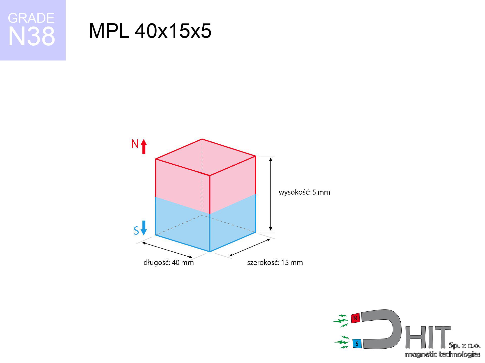
MPL 40x15x5 / N38 - lamellar magnet
lamellar magnet
Catalog no 020153
GTIN/EAN: 5906301811596
length
40 mm [±0,1 mm]
Width
15 mm [±0,1 mm]
Height
5 mm [±0,1 mm]
Weight
22.5 g
Magnetization Direction
↑ axial
Load capacity
11.35 kg / 111.37 N
Magnetic Induction
249.11 mT / 2491 Gs
Coating
[NiCuNi] Nickel
7.63 ZŁ with VAT / pcs + price for transport
6.20 ZŁ net + 23% VAT / pcs
bulk discounts:
Need more?
Contact us by phone
+48 22 499 98 98
or drop us a message using
our online form
the contact section.
Parameters along with appearance of a magnet can be reviewed with our
modular calculator.
Orders placed before 14:00 will be shipped the same business day.
Technical - MPL 40x15x5 / N38 - lamellar magnet
Specification / characteristics - MPL 40x15x5 / N38 - lamellar magnet
| properties | values |
|---|---|
| Cat. no. | 020153 |
| GTIN/EAN | 5906301811596 |
| Production/Distribution | Dhit sp. z o.o. |
| Country of origin | Poland / China / Germany |
| Customs code | 85059029 |
| length | 40 mm [±0,1 mm] |
| Width | 15 mm [±0,1 mm] |
| Height | 5 mm [±0,1 mm] |
| Weight | 22.5 g |
| Magnetization Direction | ↑ axial |
| Load capacity ~ ? | 11.35 kg / 111.37 N |
| Magnetic Induction ~ ? | 249.11 mT / 2491 Gs |
| Coating | [NiCuNi] Nickel |
| Manufacturing Tolerance | ±0.1 mm |
Magnetic properties of material N38
| properties | values | units |
|---|---|---|
| remenance Br [min. - max.] ? | 12.2-12.6 | kGs |
| remenance Br [min. - max.] ? | 1220-1260 | mT |
| coercivity bHc ? | 10.8-11.5 | kOe |
| coercivity bHc ? | 860-915 | kA/m |
| actual internal force iHc | ≥ 12 | kOe |
| actual internal force iHc | ≥ 955 | kA/m |
| energy density [min. - max.] ? | 36-38 | BH max MGOe |
| energy density [min. - max.] ? | 287-303 | BH max KJ/m |
| max. temperature ? | ≤ 80 | °C |
Physical properties of sintered neodymium magnets Nd2Fe14B at 20°C
| properties | values | units |
|---|---|---|
| Vickers hardness | ≥550 | Hv |
| Density | ≥7.4 | g/cm3 |
| Curie Temperature TC | 312 - 380 | °C |
| Curie Temperature TF | 593 - 716 | °F |
| Specific resistance | 150 | μΩ⋅cm |
| Bending strength | 250 | MPa |
| Compressive strength | 1000~1100 | MPa |
| Thermal expansion parallel (∥) to orientation (M) | (3-4) x 10-6 | °C-1 |
| Thermal expansion perpendicular (⊥) to orientation (M) | -(1-3) x 10-6 | °C-1 |
| Young's modulus | 1.7 x 10⁴ | kg/mm² |
Engineering analysis of the magnet - report
These data are the direct effect of a engineering simulation. Values are based on algorithms for the material Nd2Fe14B. Real-world conditions may deviate from the simulation results. Please consider these data as a preliminary roadmap for designers.
Table 1: Static force (force vs distance) - power drop
MPL 40x15x5 / N38
| Distance (mm) | Induction (Gauss) / mT | Pull Force (kg/lbs/g/N) | Risk Status |
|---|---|---|---|
| 0 mm |
2490 Gs
249.0 mT
|
11.35 kg / 25.02 lbs
11350.0 g / 111.3 N
|
crushing |
| 1 mm |
2306 Gs
230.6 mT
|
9.73 kg / 21.45 lbs
9731.3 g / 95.5 N
|
strong |
| 2 mm |
2095 Gs
209.5 mT
|
8.03 kg / 17.70 lbs
8028.8 g / 78.8 N
|
strong |
| 3 mm |
1877 Gs
187.7 mT
|
6.45 kg / 14.21 lbs
6445.4 g / 63.2 N
|
strong |
| 5 mm |
1472 Gs
147.2 mT
|
3.97 kg / 8.74 lbs
3965.1 g / 38.9 N
|
strong |
| 10 mm |
792 Gs
79.2 mT
|
1.15 kg / 2.53 lbs
1147.1 g / 11.3 N
|
weak grip |
| 15 mm |
454 Gs
45.4 mT
|
0.38 kg / 0.83 lbs
376.9 g / 3.7 N
|
weak grip |
| 20 mm |
278 Gs
27.8 mT
|
0.14 kg / 0.31 lbs
141.4 g / 1.4 N
|
weak grip |
| 30 mm |
122 Gs
12.2 mT
|
0.03 kg / 0.06 lbs
27.0 g / 0.3 N
|
weak grip |
| 50 mm |
35 Gs
3.5 mT
|
0.00 kg / 0.01 lbs
2.3 g / 0.0 N
|
weak grip |
Table 2: Vertical force (wall)
MPL 40x15x5 / N38
| Distance (mm) | Friction coefficient | Pull Force (kg/lbs/g/N) |
|---|---|---|
| 0 mm | Stal (~0.2) |
2.27 kg / 5.00 lbs
2270.0 g / 22.3 N
|
| 1 mm | Stal (~0.2) |
1.95 kg / 4.29 lbs
1946.0 g / 19.1 N
|
| 2 mm | Stal (~0.2) |
1.61 kg / 3.54 lbs
1606.0 g / 15.8 N
|
| 3 mm | Stal (~0.2) |
1.29 kg / 2.84 lbs
1290.0 g / 12.7 N
|
| 5 mm | Stal (~0.2) |
0.79 kg / 1.75 lbs
794.0 g / 7.8 N
|
| 10 mm | Stal (~0.2) |
0.23 kg / 0.51 lbs
230.0 g / 2.3 N
|
| 15 mm | Stal (~0.2) |
0.08 kg / 0.17 lbs
76.0 g / 0.7 N
|
| 20 mm | Stal (~0.2) |
0.03 kg / 0.06 lbs
28.0 g / 0.3 N
|
| 30 mm | Stal (~0.2) |
0.01 kg / 0.01 lbs
6.0 g / 0.1 N
|
| 50 mm | Stal (~0.2) |
0.00 kg / 0.00 lbs
0.0 g / 0.0 N
|
Table 3: Wall mounting (sliding) - behavior on slippery surfaces
MPL 40x15x5 / N38
| Surface type | Friction coefficient / % Mocy | Max load (kg/lbs/g/N) |
|---|---|---|
| Raw steel |
µ = 0.3
30% Nominalnej Siły
|
3.41 kg / 7.51 lbs
3405.0 g / 33.4 N
|
| Painted steel (standard) |
µ = 0.2
20% Nominalnej Siły
|
2.27 kg / 5.00 lbs
2270.0 g / 22.3 N
|
| Oily/slippery steel |
µ = 0.1
10% Nominalnej Siły
|
1.14 kg / 2.50 lbs
1135.0 g / 11.1 N
|
| Magnet with anti-slip rubber |
µ = 0.5
50% Nominalnej Siły
|
5.68 kg / 12.51 lbs
5675.0 g / 55.7 N
|
Table 4: Material efficiency (saturation) - sheet metal selection
MPL 40x15x5 / N38
| Steel thickness (mm) | % power | Real pull force (kg/lbs/g/N) |
|---|---|---|
| 0.5 mm |
|
0.57 kg / 1.25 lbs
567.5 g / 5.6 N
|
| 1 mm |
|
1.42 kg / 3.13 lbs
1418.8 g / 13.9 N
|
| 2 mm |
|
2.84 kg / 6.26 lbs
2837.5 g / 27.8 N
|
| 3 mm |
|
4.26 kg / 9.38 lbs
4256.3 g / 41.8 N
|
| 5 mm |
|
7.09 kg / 15.64 lbs
7093.8 g / 69.6 N
|
| 10 mm |
|
11.35 kg / 25.02 lbs
11350.0 g / 111.3 N
|
| 11 mm |
|
11.35 kg / 25.02 lbs
11350.0 g / 111.3 N
|
| 12 mm |
|
11.35 kg / 25.02 lbs
11350.0 g / 111.3 N
|
Table 5: Thermal stability (material behavior) - resistance threshold
MPL 40x15x5 / N38
| Ambient temp. (°C) | Power loss | Remaining pull (kg/lbs/g/N) | Status |
|---|---|---|---|
| 20 °C | 0.0% |
11.35 kg / 25.02 lbs
11350.0 g / 111.3 N
|
OK |
| 40 °C | -2.2% |
11.10 kg / 24.47 lbs
11100.3 g / 108.9 N
|
OK |
| 60 °C | -4.4% |
10.85 kg / 23.92 lbs
10850.6 g / 106.4 N
|
|
| 80 °C | -6.6% |
10.60 kg / 23.37 lbs
10600.9 g / 104.0 N
|
|
| 100 °C | -28.8% |
8.08 kg / 17.82 lbs
8081.2 g / 79.3 N
|
Table 6: Magnet-Magnet interaction (attraction) - field range
MPL 40x15x5 / N38
| Gap (mm) | Attraction (kg/lbs) (N-S) | Sliding Force (kg/lbs/g/N) | Repulsion (kg/lbs) (N-N) |
|---|---|---|---|
| 0 mm |
22.94 kg / 50.58 lbs
3 961 Gs
|
3.44 kg / 7.59 lbs
3441 g / 33.8 N
|
N/A |
| 1 mm |
21.37 kg / 47.11 lbs
4 807 Gs
|
3.21 kg / 7.07 lbs
3205 g / 31.4 N
|
19.23 kg / 42.40 lbs
~0 Gs
|
| 2 mm |
19.67 kg / 43.37 lbs
4 612 Gs
|
2.95 kg / 6.50 lbs
2951 g / 28.9 N
|
17.70 kg / 39.03 lbs
~0 Gs
|
| 3 mm |
17.94 kg / 39.55 lbs
4 404 Gs
|
2.69 kg / 5.93 lbs
2691 g / 26.4 N
|
16.15 kg / 35.59 lbs
~0 Gs
|
| 5 mm |
14.58 kg / 32.15 lbs
3 971 Gs
|
2.19 kg / 4.82 lbs
2187 g / 21.5 N
|
13.12 kg / 28.93 lbs
~0 Gs
|
| 10 mm |
8.01 kg / 17.67 lbs
2 944 Gs
|
1.20 kg / 2.65 lbs
1202 g / 11.8 N
|
7.21 kg / 15.90 lbs
~0 Gs
|
| 20 mm |
2.32 kg / 5.11 lbs
1 583 Gs
|
0.35 kg / 0.77 lbs
348 g / 3.4 N
|
2.09 kg / 4.60 lbs
~0 Gs
|
| 50 mm |
0.12 kg / 0.26 lbs
359 Gs
|
0.02 kg / 0.04 lbs
18 g / 0.2 N
|
0.11 kg / 0.24 lbs
~0 Gs
|
| 60 mm |
0.05 kg / 0.12 lbs
243 Gs
|
0.01 kg / 0.02 lbs
8 g / 0.1 N
|
0.05 kg / 0.11 lbs
~0 Gs
|
| 70 mm |
0.03 kg / 0.06 lbs
171 Gs
|
0.00 kg / 0.01 lbs
4 g / 0.0 N
|
0.02 kg / 0.05 lbs
~0 Gs
|
| 80 mm |
0.01 kg / 0.03 lbs
124 Gs
|
0.00 kg / 0.00 lbs
2 g / 0.0 N
|
0.01 kg / 0.03 lbs
~0 Gs
|
| 90 mm |
0.01 kg / 0.02 lbs
92 Gs
|
0.00 kg / 0.00 lbs
1 g / 0.0 N
|
0.00 kg / 0.00 lbs
~0 Gs
|
| 100 mm |
0.00 kg / 0.01 lbs
70 Gs
|
0.00 kg / 0.00 lbs
1 g / 0.0 N
|
0.00 kg / 0.00 lbs
~0 Gs
|
Table 7: Safety (HSE) (implants) - precautionary measures
MPL 40x15x5 / N38
| Object / Device | Limit (Gauss) / mT | Safe distance |
|---|---|---|
| Pacemaker | 5 Gs (0.5 mT) | 10.5 cm |
| Hearing aid | 10 Gs (1.0 mT) | 8.0 cm |
| Timepiece | 20 Gs (2.0 mT) | 6.5 cm |
| Mobile device | 40 Gs (4.0 mT) | 5.0 cm |
| Car key | 50 Gs (5.0 mT) | 4.5 cm |
| Payment card | 400 Gs (40.0 mT) | 2.0 cm |
| HDD hard drive | 600 Gs (60.0 mT) | 1.5 cm |
Table 8: Dynamics (kinetic energy) - collision effects
MPL 40x15x5 / N38
| Start from (mm) | Speed (km/h) | Energy (J) | Predicted outcome |
|---|---|---|---|
| 10 mm |
24.04 km/h
(6.68 m/s)
|
0.50 J | |
| 30 mm |
39.29 km/h
(10.91 m/s)
|
1.34 J | |
| 50 mm |
50.66 km/h
(14.07 m/s)
|
2.23 J | |
| 100 mm |
71.63 km/h
(19.90 m/s)
|
4.45 J |
Table 9: Surface protection spec
MPL 40x15x5 / N38
| Technical parameter | Value / Description |
|---|---|
| Coating type | [NiCuNi] Nickel |
| Layer structure | Nickel - Copper - Nickel |
| Layer thickness | 10-20 µm |
| Salt spray test (SST) ? | 24 h |
| Recommended environment | Indoors only (dry) |
Table 10: Electrical data (Flux)
MPL 40x15x5 / N38
| Parameter | Value | SI Unit / Description |
|---|---|---|
| Magnetic Flux | 14 969 Mx | 149.7 µWb |
| Pc Coefficient | 0.26 | Low (Flat) |
Table 11: Physics of underwater searching
MPL 40x15x5 / N38
| Environment | Effective steel pull | Effect |
|---|---|---|
| Air (land) | 11.35 kg | Standard |
| Water (riverbed) |
13.00 kg
(+1.65 kg buoyancy gain)
|
+14.5% |
1. Vertical hold
*Note: On a vertical surface, the magnet retains just ~20% of its max power.
2. Steel thickness impact
*Thin metal sheet (e.g. 0.5mm PC case) significantly reduces the holding force.
3. Thermal stability
*For N38 material, the critical limit is 80°C.
4. Demagnetization curve and operating point (B-H)
chart generated for the permeance coefficient Pc (Permeance Coefficient) = 0.26
This simulation demonstrates the magnetic stability of the selected magnet under specific geometric conditions. The solid red line represents the demagnetization curve (material potential), while the dashed blue line is the load line based on the magnet's geometry. The Pc (Permeance Coefficient), also known as the load line slope, is a dimensionless value that describes the relationship between the magnet's shape and its magnetic stability. The intersection of these two lines (the black dot) is the operating point — it determines the actual magnetic flux density generated by the magnet in this specific configuration. A higher Pc value means the magnet is more 'slender' (tall relative to its area), resulting in a higher operating point and better resistance to irreversible demagnetization caused by external fields or temperature. A value of 0.42 is relatively low (typical for flat magnets), meaning the operating point is closer to the 'knee' of the curve — caution is advised when operating at temperatures near the maximum limit to avoid strength loss.
Elemental analysis
| iron (Fe) | 64% – 68% |
| neodymium (Nd) | 29% – 32% |
| boron (B) | 1.1% – 1.2% |
| dysprosium (Dy) | 0.5% – 2.0% |
| coating (Ni-Cu-Ni) | < 0.05% |
Environmental data
| recyclability (EoL) | 100% |
| recycled raw materials | ~10% (pre-cons) |
| carbon footprint | low / zredukowany |
| waste code (EWC) | 16 02 16 |
Other products


![SM 25x100 [2xM8] / N42 - magnetic separator](https://cdn3.dhit.pl/graphics/products/sm-25x100-2xm8-feg.jpg "SM 25x100 [2xM8] / N42 - magnetic separator")

Pros as well as cons of Nd2Fe14B magnets.
Strengths
- Their magnetic field is durable, and after approximately 10 years it drops only by ~1% (according to research),
- They are noted for resistance to demagnetization induced by presence of other magnetic fields,
- In other words, due to the aesthetic surface of nickel, the element looks attractive,
- Magnets possess extremely high magnetic induction on the outer layer,
- Due to their durability and thermal resistance, neodymium magnets are capable of operate (depending on the shape) even at high temperatures reaching 230°C or more...
- Due to the potential of free shaping and adaptation to individualized requirements, NdFeB magnets can be created in a broad palette of shapes and sizes, which increases their versatility,
- Key role in high-tech industry – they are commonly used in computer drives, electromotive mechanisms, diagnostic systems, as well as complex engineering applications.
- Compactness – despite small sizes they generate large force, making them ideal for precision applications
Limitations
- At very strong impacts they can crack, therefore we advise placing them in strong housings. A metal housing provides additional protection against damage, as well as increases the magnet's durability.
- NdFeB magnets lose power when exposed to high temperatures. After reaching 80°C, many of them experience permanent drop of power (a factor is the shape as well as dimensions of the magnet). We offer magnets specially adapted to work at temperatures up to 230°C marked [AH], which are very resistant to heat
- Magnets exposed to a humid environment can corrode. Therefore when using outdoors, we suggest using waterproof magnets made of rubber, plastic or other material resistant to moisture
- Due to limitations in producing threads and complex forms in magnets, we recommend using a housing - magnetic mount.
- Potential hazard resulting from small fragments of magnets pose a threat, in case of ingestion, which gains importance in the context of child safety. It is also worth noting that tiny parts of these products can be problematic in diagnostics medical after entering the body.
- Higher cost of purchase is one of the disadvantages compared to ceramic magnets, especially in budget applications
Holding force characteristics
Highest magnetic holding force – what contributes to it?
- on a plate made of mild steel, effectively closing the magnetic flux
- possessing a massiveness of at least 10 mm to ensure full flux closure
- characterized by even structure
- with direct contact (without coatings)
- under vertical force direction (90-degree angle)
- in neutral thermal conditions
Key elements affecting lifting force
- Gap between surfaces – even a fraction of a millimeter of distance (caused e.g. by varnish or dirt) diminishes the pulling force, often by half at just 0.5 mm.
- Load vector – maximum parameter is obtained only during perpendicular pulling. The shear force of the magnet along the plate is usually several times smaller (approx. 1/5 of the lifting capacity).
- Element thickness – to utilize 100% power, the steel must be sufficiently thick. Thin sheet limits the lifting capacity (the magnet "punches through" it).
- Material composition – not every steel reacts the same. Alloy additives worsen the attraction effect.
- Plate texture – smooth surfaces ensure maximum contact, which increases field saturation. Rough surfaces reduce efficiency.
- Operating temperature – neodymium magnets have a negative temperature coefficient. At higher temperatures they lose power, and in frost gain strength (up to a certain limit).
Lifting capacity testing was performed on a smooth plate of optimal thickness, under a perpendicular pulling force, whereas under shearing force the lifting capacity is smaller. Moreover, even a minimal clearance between the magnet’s surface and the plate lowers the holding force.
Warnings
Respect the power
Before starting, read the rules. Sudden snapping can break the magnet or hurt your hand. Think ahead.
Dust is flammable
Dust produced during grinding of magnets is flammable. Do not drill into magnets unless you are an expert.
Pinching danger
Pinching hazard: The attraction force is so immense that it can result in hematomas, pinching, and broken bones. Use thick gloves.
Keep away from electronics
Navigation devices and smartphones are highly susceptible to magnetic fields. Close proximity with a powerful NdFeB magnet can permanently damage the sensors in your phone.
Medical interference
Warning for patients: Powerful magnets affect medical devices. Maintain at least 30 cm distance or request help to work with the magnets.
Thermal limits
Watch the temperature. Heating the magnet to high heat will permanently weaken its magnetic structure and pulling force.
Avoid contact if allergic
Certain individuals have a hypersensitivity to nickel, which is the typical protective layer for NdFeB magnets. Frequent touching can result in a rash. We suggest wear protective gloves.
Safe distance
Intense magnetic fields can destroy records on payment cards, HDDs, and other magnetic media. Maintain a gap of at least 10 cm.
Protective goggles
NdFeB magnets are sintered ceramics, which means they are very brittle. Collision of two magnets leads to them breaking into small pieces.
Keep away from children
Only for adults. Small elements can be swallowed, leading to intestinal necrosis. Keep out of reach of children and animals.
Tabela kosztu i czasu dostawy
Płatność przed wysyłką:

GLS kurier
Przesyłka będzie u Ciebie za 2-3 dni
14.99 ZŁ

InPost Paczkomaty 24/7
Przesyłka będzie u Ciebie za 1-2 dni
12.30 ZŁ
Płatność przy odbiorze (pobranie):
GLS kurier
Przesyłka będzie u Ciebie za 1-2 dni
23.00 ZŁ
Rate the product
Your rating