
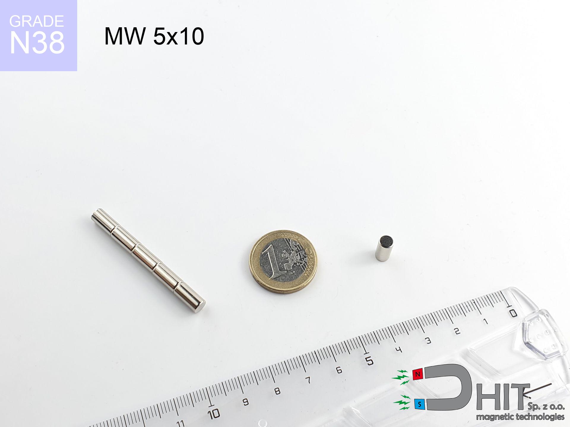
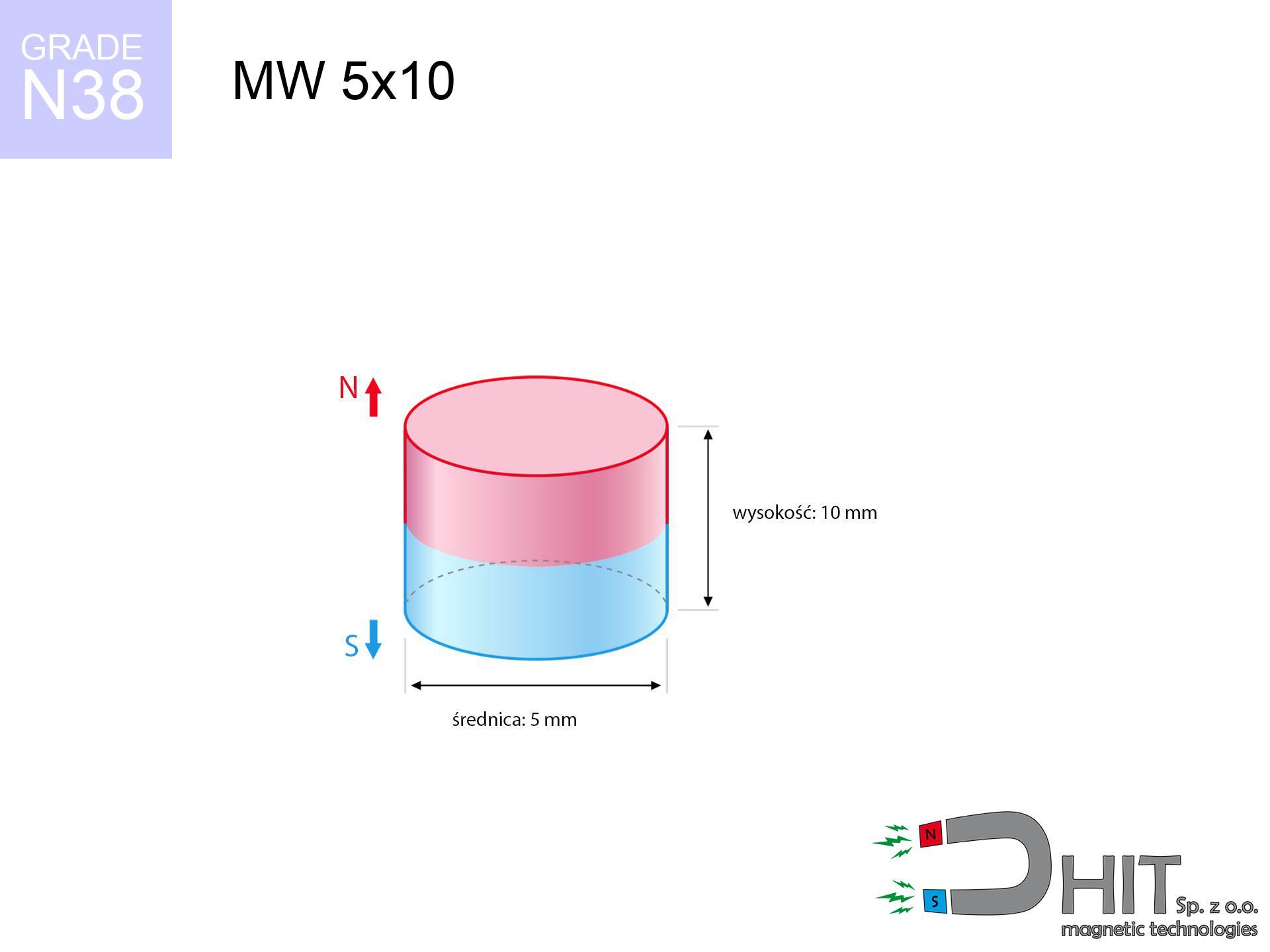
MW 5x10 / N38 - cylindrical magnet
cylindrical magnet
Catalog no 010083
GTIN/EAN: 5906301810827
Diameter Ø
5 mm [±0,1 mm]
Height
10 mm [±0,1 mm]
Weight
1.47 g
Magnetization Direction
↑ axial
Load capacity
0.56 kg / 5.45 N
Magnetic Induction
599.97 mT / 6000 Gs
Coating
[NiCuNi] Nickel
0.800 ZŁ with VAT / pcs + price for transport
0.650 ZŁ net + 23% VAT / pcs
bulk discounts:
Need more?
Contact us by phone
+48 22 499 98 98
if you prefer contact us through
contact form
the contact section.
Specifications and structure of a neodymium magnet can be calculated with our
online calculation tool.
Same-day shipping for orders placed before 14:00.
Product card - MW 5x10 / N38 - cylindrical magnet
Specification / characteristics - MW 5x10 / N38 - cylindrical magnet
| properties | values |
|---|---|
| Cat. no. | 010083 |
| GTIN/EAN | 5906301810827 |
| Production/Distribution | Dhit sp. z o.o. |
| Country of origin | Poland / China / Germany |
| Customs code | 85059029 |
| Diameter Ø | 5 mm [±0,1 mm] |
| Height | 10 mm [±0,1 mm] |
| Weight | 1.47 g |
| Magnetization Direction | ↑ axial |
| Load capacity ~ ? | 0.56 kg / 5.45 N |
| Magnetic Induction ~ ? | 599.97 mT / 6000 Gs |
| Coating | [NiCuNi] Nickel |
| Manufacturing Tolerance | ±0.1 mm |
Magnetic properties of material N38
| properties | values | units |
|---|---|---|
| remenance Br [min. - max.] ? | 12.2-12.6 | kGs |
| remenance Br [min. - max.] ? | 1220-1260 | mT |
| coercivity bHc ? | 10.8-11.5 | kOe |
| coercivity bHc ? | 860-915 | kA/m |
| actual internal force iHc | ≥ 12 | kOe |
| actual internal force iHc | ≥ 955 | kA/m |
| energy density [min. - max.] ? | 36-38 | BH max MGOe |
| energy density [min. - max.] ? | 287-303 | BH max KJ/m |
| max. temperature ? | ≤ 80 | °C |
Physical properties of sintered neodymium magnets Nd2Fe14B at 20°C
| properties | values | units |
|---|---|---|
| Vickers hardness | ≥550 | Hv |
| Density | ≥7.4 | g/cm3 |
| Curie Temperature TC | 312 - 380 | °C |
| Curie Temperature TF | 593 - 716 | °F |
| Specific resistance | 150 | μΩ⋅cm |
| Bending strength | 250 | MPa |
| Compressive strength | 1000~1100 | MPa |
| Thermal expansion parallel (∥) to orientation (M) | (3-4) x 10-6 | °C-1 |
| Thermal expansion perpendicular (⊥) to orientation (M) | -(1-3) x 10-6 | °C-1 |
| Young's modulus | 1.7 x 10⁴ | kg/mm² |
Engineering modeling of the assembly - data
Presented information are the result of a physical calculation. Values rely on algorithms for the material Nd2Fe14B. Operational parameters might slightly differ. Please consider these calculations as a supplementary guide for designers.
Table 1: Static pull force (pull vs distance) - power drop
MW 5x10 / N38
| Distance (mm) | Induction (Gauss) / mT | Pull Force (kg/lbs/g/N) | Risk Status |
|---|---|---|---|
| 0 mm |
5990 Gs
599.0 mT
|
0.56 kg / 1.23 pounds
560.0 g / 5.5 N
|
weak grip |
| 1 mm |
3743 Gs
374.3 mT
|
0.22 kg / 0.48 pounds
218.7 g / 2.1 N
|
weak grip |
| 2 mm |
2197 Gs
219.7 mT
|
0.08 kg / 0.17 pounds
75.3 g / 0.7 N
|
weak grip |
| 3 mm |
1325 Gs
132.5 mT
|
0.03 kg / 0.06 pounds
27.4 g / 0.3 N
|
weak grip |
| 5 mm |
570 Gs
57.0 mT
|
0.01 kg / 0.01 pounds
5.1 g / 0.0 N
|
weak grip |
| 10 mm |
137 Gs
13.7 mT
|
0.00 kg / 0.00 pounds
0.3 g / 0.0 N
|
weak grip |
| 15 mm |
54 Gs
5.4 mT
|
0.00 kg / 0.00 pounds
0.0 g / 0.0 N
|
weak grip |
| 20 mm |
26 Gs
2.6 mT
|
0.00 kg / 0.00 pounds
0.0 g / 0.0 N
|
weak grip |
| 30 mm |
9 Gs
0.9 mT
|
0.00 kg / 0.00 pounds
0.0 g / 0.0 N
|
weak grip |
| 50 mm |
2 Gs
0.2 mT
|
0.00 kg / 0.00 pounds
0.0 g / 0.0 N
|
weak grip |
Table 2: Vertical capacity (wall)
MW 5x10 / N38
| Distance (mm) | Friction coefficient | Pull Force (kg/lbs/g/N) |
|---|---|---|
| 0 mm | Stal (~0.2) |
0.11 kg / 0.25 pounds
112.0 g / 1.1 N
|
| 1 mm | Stal (~0.2) |
0.04 kg / 0.10 pounds
44.0 g / 0.4 N
|
| 2 mm | Stal (~0.2) |
0.02 kg / 0.04 pounds
16.0 g / 0.2 N
|
| 3 mm | Stal (~0.2) |
0.01 kg / 0.01 pounds
6.0 g / 0.1 N
|
| 5 mm | Stal (~0.2) |
0.00 kg / 0.00 pounds
2.0 g / 0.0 N
|
| 10 mm | Stal (~0.2) |
0.00 kg / 0.00 pounds
0.0 g / 0.0 N
|
| 15 mm | Stal (~0.2) |
0.00 kg / 0.00 pounds
0.0 g / 0.0 N
|
| 20 mm | Stal (~0.2) |
0.00 kg / 0.00 pounds
0.0 g / 0.0 N
|
| 30 mm | Stal (~0.2) |
0.00 kg / 0.00 pounds
0.0 g / 0.0 N
|
| 50 mm | Stal (~0.2) |
0.00 kg / 0.00 pounds
0.0 g / 0.0 N
|
Table 3: Wall mounting (sliding) - behavior on slippery surfaces
MW 5x10 / N38
| Surface type | Friction coefficient / % Mocy | Max load (kg/lbs/g/N) |
|---|---|---|
| Raw steel |
µ = 0.3
30% Nominalnej Siły
|
0.17 kg / 0.37 pounds
168.0 g / 1.6 N
|
| Painted steel (standard) |
µ = 0.2
20% Nominalnej Siły
|
0.11 kg / 0.25 pounds
112.0 g / 1.1 N
|
| Oily/slippery steel |
µ = 0.1
10% Nominalnej Siły
|
0.06 kg / 0.12 pounds
56.0 g / 0.5 N
|
| Magnet with anti-slip rubber |
µ = 0.5
50% Nominalnej Siły
|
0.28 kg / 0.62 pounds
280.0 g / 2.7 N
|
Table 4: Steel thickness (saturation) - power losses
MW 5x10 / N38
| Steel thickness (mm) | % power | Real pull force (kg/lbs/g/N) |
|---|---|---|
| 0.5 mm |
|
0.06 kg / 0.12 pounds
56.0 g / 0.5 N
|
| 1 mm |
|
0.14 kg / 0.31 pounds
140.0 g / 1.4 N
|
| 2 mm |
|
0.28 kg / 0.62 pounds
280.0 g / 2.7 N
|
| 3 mm |
|
0.42 kg / 0.93 pounds
420.0 g / 4.1 N
|
| 5 mm |
|
0.56 kg / 1.23 pounds
560.0 g / 5.5 N
|
| 10 mm |
|
0.56 kg / 1.23 pounds
560.0 g / 5.5 N
|
| 11 mm |
|
0.56 kg / 1.23 pounds
560.0 g / 5.5 N
|
| 12 mm |
|
0.56 kg / 1.23 pounds
560.0 g / 5.5 N
|
Table 5: Thermal resistance (stability) - thermal limit
MW 5x10 / N38
| Ambient temp. (°C) | Power loss | Remaining pull (kg/lbs/g/N) | Status |
|---|---|---|---|
| 20 °C | 0.0% |
0.56 kg / 1.23 pounds
560.0 g / 5.5 N
|
OK |
| 40 °C | -2.2% |
0.55 kg / 1.21 pounds
547.7 g / 5.4 N
|
OK |
| 60 °C | -4.4% |
0.54 kg / 1.18 pounds
535.4 g / 5.3 N
|
OK |
| 80 °C | -6.6% |
0.52 kg / 1.15 pounds
523.0 g / 5.1 N
|
|
| 100 °C | -28.8% |
0.40 kg / 0.88 pounds
398.7 g / 3.9 N
|
Table 6: Two magnets (repulsion) - field range
MW 5x10 / N38
| Gap (mm) | Attraction (kg/lbs) (N-S) | Shear Strength (kg/lbs/g/N) | Repulsion (kg/lbs) (N-N) |
|---|---|---|---|
| 0 mm |
4.34 kg / 9.58 pounds
6 127 Gs
|
0.65 kg / 1.44 pounds
652 g / 6.4 N
|
N/A |
| 1 mm |
2.81 kg / 6.19 pounds
9 631 Gs
|
0.42 kg / 0.93 pounds
421 g / 4.1 N
|
2.53 kg / 5.57 pounds
~0 Gs
|
| 2 mm |
1.70 kg / 3.74 pounds
7 486 Gs
|
0.25 kg / 0.56 pounds
254 g / 2.5 N
|
1.53 kg / 3.37 pounds
~0 Gs
|
| 3 mm |
1.00 kg / 2.20 pounds
5 737 Gs
|
0.15 kg / 0.33 pounds
149 g / 1.5 N
|
0.90 kg / 1.98 pounds
~0 Gs
|
| 5 mm |
0.35 kg / 0.77 pounds
3 391 Gs
|
0.05 kg / 0.12 pounds
52 g / 0.5 N
|
0.31 kg / 0.69 pounds
~0 Gs
|
| 10 mm |
0.04 kg / 0.09 pounds
1 140 Gs
|
0.01 kg / 0.01 pounds
6 g / 0.1 N
|
0.04 kg / 0.08 pounds
~0 Gs
|
| 20 mm |
0.00 kg / 0.01 pounds
274 Gs
|
0.00 kg / 0.00 pounds
0 g / 0.0 N
|
0.00 kg / 0.00 pounds
~0 Gs
|
| 50 mm |
0.00 kg / 0.00 pounds
30 Gs
|
0.00 kg / 0.00 pounds
0 g / 0.0 N
|
0.00 kg / 0.00 pounds
~0 Gs
|
| 60 mm |
0.00 kg / 0.00 pounds
19 Gs
|
0.00 kg / 0.00 pounds
0 g / 0.0 N
|
0.00 kg / 0.00 pounds
~0 Gs
|
| 70 mm |
0.00 kg / 0.00 pounds
12 Gs
|
0.00 kg / 0.00 pounds
0 g / 0.0 N
|
0.00 kg / 0.00 pounds
~0 Gs
|
| 80 mm |
0.00 kg / 0.00 pounds
9 Gs
|
0.00 kg / 0.00 pounds
0 g / 0.0 N
|
0.00 kg / 0.00 pounds
~0 Gs
|
| 90 mm |
0.00 kg / 0.00 pounds
6 Gs
|
0.00 kg / 0.00 pounds
0 g / 0.0 N
|
0.00 kg / 0.00 pounds
~0 Gs
|
| 100 mm |
0.00 kg / 0.00 pounds
5 Gs
|
0.00 kg / 0.00 pounds
0 g / 0.0 N
|
0.00 kg / 0.00 pounds
~0 Gs
|
Table 7: Hazards (implants) - precautionary measures
MW 5x10 / N38
| Object / Device | Limit (Gauss) / mT | Safe distance |
|---|---|---|
| Pacemaker | 5 Gs (0.5 mT) | 4.0 cm |
| Hearing aid | 10 Gs (1.0 mT) | 3.0 cm |
| Timepiece | 20 Gs (2.0 mT) | 2.5 cm |
| Mobile device | 40 Gs (4.0 mT) | 2.0 cm |
| Remote | 50 Gs (5.0 mT) | 2.0 cm |
| Payment card | 400 Gs (40.0 mT) | 1.0 cm |
| HDD hard drive | 600 Gs (60.0 mT) | 0.5 cm |
Table 8: Impact energy (cracking risk) - warning
MW 5x10 / N38
| Start from (mm) | Speed (km/h) | Energy (J) | Predicted outcome |
|---|---|---|---|
| 10 mm |
19.69 km/h
(5.47 m/s)
|
0.02 J | |
| 30 mm |
34.09 km/h
(9.47 m/s)
|
0.07 J | |
| 50 mm |
44.02 km/h
(12.23 m/s)
|
0.11 J | |
| 100 mm |
62.25 km/h
(17.29 m/s)
|
0.22 J |
Table 9: Corrosion resistance
MW 5x10 / N38
| Technical parameter | Value / Description |
|---|---|
| Coating type | [NiCuNi] Nickel |
| Layer structure | Nickel - Copper - Nickel |
| Layer thickness | 10-20 µm |
| Salt spray test (SST) ? | 24 h |
| Recommended environment | Indoors only (dry) |
Table 10: Construction data (Flux)
MW 5x10 / N38
| Parameter | Value | SI Unit / Description |
|---|---|---|
| Magnetic Flux | 1 306 Mx | 13.1 µWb |
| Pc Coefficient | 1.21 | High (Stable) |
Table 11: Underwater work (magnet fishing)
MW 5x10 / N38
| Environment | Effective steel pull | Effect |
|---|---|---|
| Air (land) | 0.56 kg | Standard |
| Water (riverbed) |
0.64 kg
(+0.08 kg buoyancy gain)
|
+14.5% |
1. Wall mount (shear)
*Note: On a vertical surface, the magnet holds merely approx. 20-30% of its max power.
2. Efficiency vs thickness
*Thin steel (e.g. computer case) drastically limits the holding force.
3. Temperature resistance
*For N38 material, the critical limit is 80°C.
4. Demagnetization curve and operating point (B-H)
chart generated for the permeance coefficient Pc (Permeance Coefficient) = 1.21
This simulation demonstrates the magnetic stability of the selected magnet under specific geometric conditions. The solid red line represents the demagnetization curve (material potential), while the dashed blue line is the load line based on the magnet's geometry. The Pc (Permeance Coefficient), also known as the load line slope, is a dimensionless value that describes the relationship between the magnet's shape and its magnetic stability. The intersection of these two lines (the black dot) is the operating point — it determines the actual magnetic flux density generated by the magnet in this specific configuration. A higher Pc value means the magnet is more 'slender' (tall relative to its area), resulting in a higher operating point and better resistance to irreversible demagnetization caused by external fields or temperature. A value of 0.42 is relatively low (typical for flat magnets), meaning the operating point is closer to the 'knee' of the curve — caution is advised when operating at temperatures near the maximum limit to avoid strength loss.
Chemical composition
| iron (Fe) | 64% – 68% |
| neodymium (Nd) | 29% – 32% |
| boron (B) | 1.1% – 1.2% |
| dysprosium (Dy) | 0.5% – 2.0% |
| coating (Ni-Cu-Ni) | < 0.05% |
Sustainability
| recyclability (EoL) | 100% |
| recycled raw materials | ~10% (pre-cons) |
| carbon footprint | low / zredukowany |
| waste code (EWC) | 16 02 16 |
View also deals


Pros and cons of neodymium magnets.
Advantages
- They have constant strength, and over around 10 years their performance decreases symbolically – ~1% (according to theory),
- They maintain their magnetic properties even under external field action,
- Thanks to the shimmering finish, the plating of nickel, gold-plated, or silver gives an elegant appearance,
- Neodymium magnets deliver maximum magnetic induction on a contact point, which increases force concentration,
- Through (appropriate) combination of ingredients, they can achieve high thermal strength, allowing for action at temperatures approaching 230°C and above...
- Due to the ability of accurate forming and adaptation to individualized projects, magnetic components can be created in a variety of forms and dimensions, which increases their versatility,
- Wide application in modern technologies – they find application in hard drives, motor assemblies, medical equipment, as well as multitasking production systems.
- Relatively small size with high pulling force – neodymium magnets offer high power in compact dimensions, which enables their usage in small systems
Cons
- They are fragile upon heavy impacts. To avoid cracks, it is worth protecting magnets in special housings. Such protection not only protects the magnet but also increases its resistance to damage
- Neodymium magnets decrease their force under the influence of heating. As soon as 80°C is exceeded, many of them start losing their power. Therefore, we recommend our special magnets marked [AH], which maintain durability even at temperatures up to 230°C
- Magnets exposed to a humid environment can corrode. Therefore when using outdoors, we advise using waterproof magnets made of rubber, plastic or other material protecting against moisture
- Limited possibility of producing nuts in the magnet and complex shapes - preferred is casing - magnet mounting.
- Possible danger related to microscopic parts of magnets are risky, when accidentally swallowed, which is particularly important in the context of child safety. It is also worth noting that small components of these magnets are able to complicate diagnosis medical in case of swallowing.
- Due to complex production process, their price exceeds standard values,
Holding force characteristics
Magnetic strength at its maximum – what affects it?
- with the use of a sheet made of low-carbon steel, ensuring maximum field concentration
- whose thickness reaches at least 10 mm
- with an ideally smooth touching surface
- without the slightest clearance between the magnet and steel
- under perpendicular force vector (90-degree angle)
- in stable room temperature
Magnet lifting force in use – key factors
- Clearance – existence of any layer (rust, tape, air) acts as an insulator, which lowers power steeply (even by 50% at 0.5 mm).
- Force direction – catalog parameter refers to pulling vertically. When slipping, the magnet exhibits significantly lower power (typically approx. 20-30% of nominal force).
- Steel thickness – too thin plate causes magnetic saturation, causing part of the flux to be lost into the air.
- Material type – ideal substrate is pure iron steel. Cast iron may generate lower lifting capacity.
- Plate texture – smooth surfaces ensure maximum contact, which improves force. Rough surfaces reduce efficiency.
- Heat – neodymium magnets have a negative temperature coefficient. At higher temperatures they lose power, and at low temperatures gain strength (up to a certain limit).
Holding force was measured on the plate surface of 20 mm thickness, when the force acted perpendicularly, whereas under attempts to slide the magnet the holding force is lower. Moreover, even a minimal clearance between the magnet and the plate lowers the load capacity.
Safe handling of neodymium magnets
Power loss in heat
Avoid heat. NdFeB magnets are susceptible to heat. If you need resistance above 80°C, look for special high-temperature series (H, SH, UH).
Sensitization to coating
Certain individuals suffer from a hypersensitivity to nickel, which is the standard coating for neodymium magnets. Extended handling may cause a rash. It is best to use protective gloves.
Powerful field
Exercise caution. Neodymium magnets attract from a long distance and connect with massive power, often faster than you can react.
No play value
Neodymium magnets are not suitable for play. Eating multiple magnets may result in them connecting inside the digestive tract, which poses a direct threat to life and requires urgent medical intervention.
Serious injuries
Pinching hazard: The pulling power is so immense that it can result in blood blisters, pinching, and broken bones. Use thick gloves.
Data carriers
Do not bring magnets close to a purse, laptop, or screen. The magnetic field can destroy these devices and erase data from cards.
Pacemakers
People with a heart stimulator must maintain an absolute distance from magnets. The magnetism can stop the functioning of the life-saving device.
Compass and GPS
Remember: neodymium magnets generate a field that confuses precision electronics. Keep a safe distance from your mobile, device, and GPS.
Risk of cracking
Watch out for shards. Magnets can explode upon uncontrolled impact, ejecting shards into the air. Wear goggles.
Fire warning
Drilling and cutting of neodymium magnets carries a risk of fire risk. Magnetic powder oxidizes rapidly with oxygen and is hard to extinguish.
Tabela kosztu i czasu dostawy
Płatność przed wysyłką:

GLS kurier
Przesyłka będzie u Ciebie za 2-3 dni
14.99 ZŁ

InPost Paczkomaty 24/7
Przesyłka będzie u Ciebie za 1-2 dni
12.30 ZŁ
Płatność przy odbiorze (pobranie):
GLS kurier
Przesyłka będzie u Ciebie za 1-2 dni
23.00 ZŁ
Rate the product
Your rating