

MPL 10x10x3 / N38 - lamellar magnet
lamellar magnet
Catalog no 020111
GTIN/EAN: 5906301811176
length
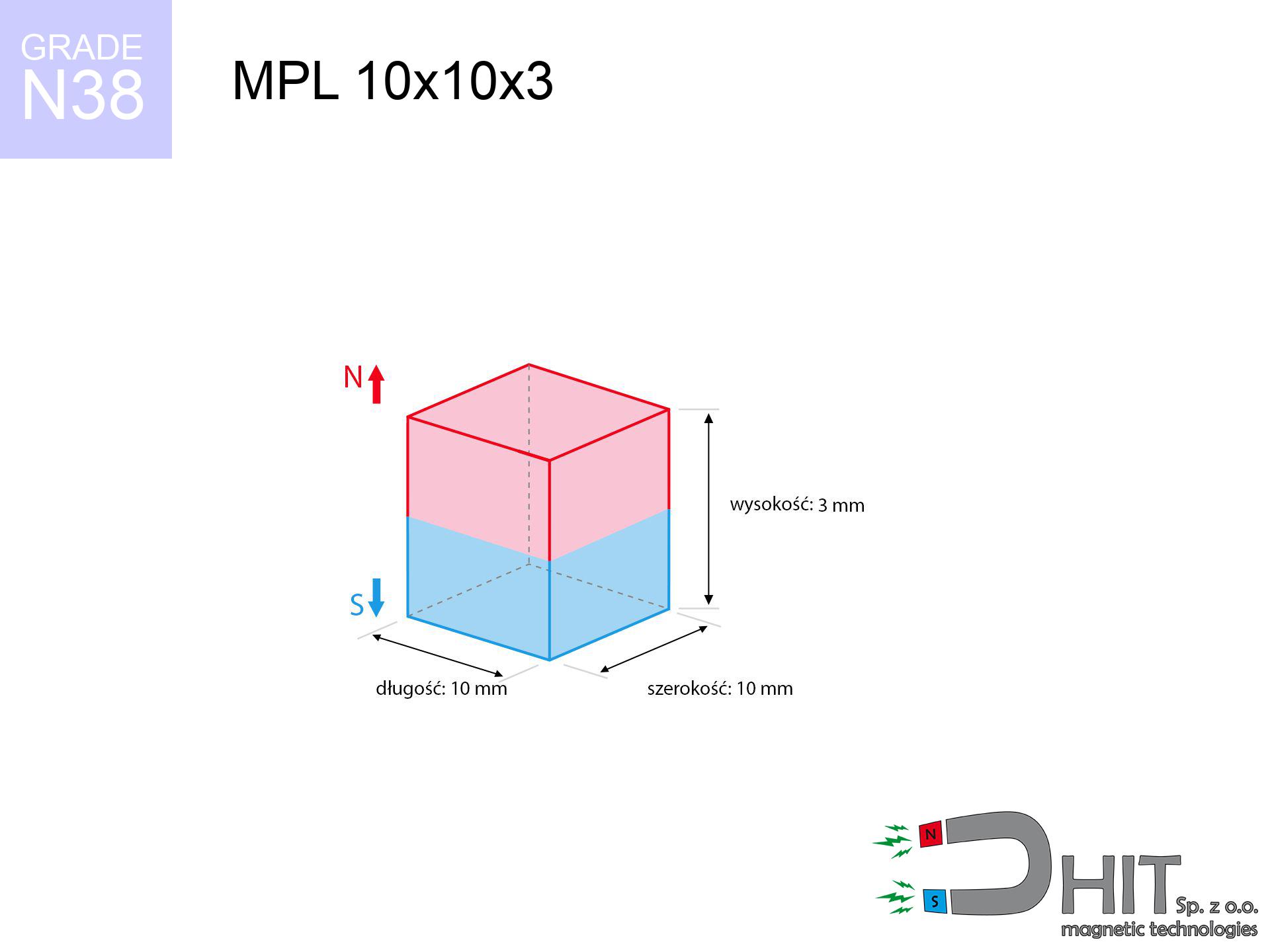
10 mm [±0,1 mm]
Width
10 mm [±0,1 mm]
Height
3 mm [±0,1 mm]
Weight
2.25 g
Magnetization Direction
↑ axial
Load capacity
2.32 kg / 22.77 N
Magnetic Induction
293.71 mT / 2937 Gs
Coating
[NiCuNi] Nickel
1.414 ZŁ with VAT / pcs + price for transport
1.150 ZŁ net + 23% VAT / pcs
bulk discounts:
Need more?
Give us a call
+48 888 99 98 98
alternatively send us a note via
request form
the contact page.
Parameters and shape of magnetic components can be checked on our
power calculator.
Orders submitted before 14:00 will be dispatched today!
Product card - MPL 10x10x3 / N38 - lamellar magnet
Specification / characteristics - MPL 10x10x3 / N38 - lamellar magnet
| properties | values |
|---|---|
| Cat. no. | 020111 |
| GTIN/EAN | 5906301811176 |
| Production/Distribution | Dhit sp. z o.o. |
| Country of origin | Poland / China / Germany |
| Customs code | 85059029 |
| length | 10 mm [±0,1 mm] |
| Width | 10 mm [±0,1 mm] |
| Height | 3 mm [±0,1 mm] |
| Weight | 2.25 g |
| Magnetization Direction | ↑ axial |
| Load capacity ~ ? | 2.32 kg / 22.77 N |
| Magnetic Induction ~ ? | 293.71 mT / 2937 Gs |
| Coating | [NiCuNi] Nickel |
| Manufacturing Tolerance | ±0.1 mm |
Magnetic properties of material N38
| properties | values | units |
|---|---|---|
| remenance Br [min. - max.] ? | 12.2-12.6 | kGs |
| remenance Br [min. - max.] ? | 1220-1260 | mT |
| coercivity bHc ? | 10.8-11.5 | kOe |
| coercivity bHc ? | 860-915 | kA/m |
| actual internal force iHc | ≥ 12 | kOe |
| actual internal force iHc | ≥ 955 | kA/m |
| energy density [min. - max.] ? | 36-38 | BH max MGOe |
| energy density [min. - max.] ? | 287-303 | BH max KJ/m |
| max. temperature ? | ≤ 80 | °C |
Physical properties of sintered neodymium magnets Nd2Fe14B at 20°C
| properties | values | units |
|---|---|---|
| Vickers hardness | ≥550 | Hv |
| Density | ≥7.4 | g/cm3 |
| Curie Temperature TC | 312 - 380 | °C |
| Curie Temperature TF | 593 - 716 | °F |
| Specific resistance | 150 | μΩ⋅cm |
| Bending strength | 250 | MPa |
| Compressive strength | 1000~1100 | MPa |
| Thermal expansion parallel (∥) to orientation (M) | (3-4) x 10-6 | °C-1 |
| Thermal expansion perpendicular (⊥) to orientation (M) | -(1-3) x 10-6 | °C-1 |
| Young's modulus | 1.7 x 10⁴ | kg/mm² |
Engineering modeling of the magnet - technical parameters
The following information are the outcome of a mathematical analysis. Values rely on models for the material Nd2Fe14B. Operational conditions may differ. Use these data as a supplementary guide for designers.
Table 1: Static force (pull vs gap) - interaction chart
MPL 10x10x3 / N38
| Distance (mm) | Induction (Gauss) / mT | Pull Force (kg/lbs/g/N) | Risk Status |
|---|---|---|---|
| 0 mm |
2936 Gs
293.6 mT
|
2.32 kg / 5.11 pounds
2320.0 g / 22.8 N
|
strong |
| 1 mm |
2513 Gs
251.3 mT
|
1.70 kg / 3.75 pounds
1700.6 g / 16.7 N
|
weak grip |
| 2 mm |
2036 Gs
203.6 mT
|
1.12 kg / 2.46 pounds
1115.5 g / 10.9 N
|
weak grip |
| 3 mm |
1594 Gs
159.4 mT
|
0.68 kg / 1.51 pounds
683.9 g / 6.7 N
|
weak grip |
| 5 mm |
943 Gs
94.3 mT
|
0.24 kg / 0.53 pounds
239.3 g / 2.3 N
|
weak grip |
| 10 mm |
285 Gs
28.5 mT
|
0.02 kg / 0.05 pounds
21.8 g / 0.2 N
|
weak grip |
| 15 mm |
112 Gs
11.2 mT
|
0.00 kg / 0.01 pounds
3.4 g / 0.0 N
|
weak grip |
| 20 mm |
54 Gs
5.4 mT
|
0.00 kg / 0.00 pounds
0.8 g / 0.0 N
|
weak grip |
| 30 mm |
18 Gs
1.8 mT
|
0.00 kg / 0.00 pounds
0.1 g / 0.0 N
|
weak grip |
| 50 mm |
4 Gs
0.4 mT
|
0.00 kg / 0.00 pounds
0.0 g / 0.0 N
|
weak grip |
Table 2: Slippage load (wall)
MPL 10x10x3 / N38
| Distance (mm) | Friction coefficient | Pull Force (kg/lbs/g/N) |
|---|---|---|
| 0 mm | Stal (~0.2) |
0.46 kg / 1.02 pounds
464.0 g / 4.6 N
|
| 1 mm | Stal (~0.2) |
0.34 kg / 0.75 pounds
340.0 g / 3.3 N
|
| 2 mm | Stal (~0.2) |
0.22 kg / 0.49 pounds
224.0 g / 2.2 N
|
| 3 mm | Stal (~0.2) |
0.14 kg / 0.30 pounds
136.0 g / 1.3 N
|
| 5 mm | Stal (~0.2) |
0.05 kg / 0.11 pounds
48.0 g / 0.5 N
|
| 10 mm | Stal (~0.2) |
0.00 kg / 0.01 pounds
4.0 g / 0.0 N
|
| 15 mm | Stal (~0.2) |
0.00 kg / 0.00 pounds
0.0 g / 0.0 N
|
| 20 mm | Stal (~0.2) |
0.00 kg / 0.00 pounds
0.0 g / 0.0 N
|
| 30 mm | Stal (~0.2) |
0.00 kg / 0.00 pounds
0.0 g / 0.0 N
|
| 50 mm | Stal (~0.2) |
0.00 kg / 0.00 pounds
0.0 g / 0.0 N
|
Table 3: Vertical assembly (sliding) - behavior on slippery surfaces
MPL 10x10x3 / N38
| Surface type | Friction coefficient / % Mocy | Max load (kg/lbs/g/N) |
|---|---|---|
| Raw steel |
µ = 0.3
30% Nominalnej Siły
|
0.70 kg / 1.53 pounds
696.0 g / 6.8 N
|
| Painted steel (standard) |
µ = 0.2
20% Nominalnej Siły
|
0.46 kg / 1.02 pounds
464.0 g / 4.6 N
|
| Oily/slippery steel |
µ = 0.1
10% Nominalnej Siły
|
0.23 kg / 0.51 pounds
232.0 g / 2.3 N
|
| Magnet with anti-slip rubber |
µ = 0.5
50% Nominalnej Siły
|
1.16 kg / 2.56 pounds
1160.0 g / 11.4 N
|
Table 4: Steel thickness (substrate influence) - power losses
MPL 10x10x3 / N38
| Steel thickness (mm) | % power | Real pull force (kg/lbs/g/N) |
|---|---|---|
| 0.5 mm |
|
0.23 kg / 0.51 pounds
232.0 g / 2.3 N
|
| 1 mm |
|
0.58 kg / 1.28 pounds
580.0 g / 5.7 N
|
| 2 mm |
|
1.16 kg / 2.56 pounds
1160.0 g / 11.4 N
|
| 3 mm |
|
1.74 kg / 3.84 pounds
1740.0 g / 17.1 N
|
| 5 mm |
|
2.32 kg / 5.11 pounds
2320.0 g / 22.8 N
|
| 10 mm |
|
2.32 kg / 5.11 pounds
2320.0 g / 22.8 N
|
| 11 mm |
|
2.32 kg / 5.11 pounds
2320.0 g / 22.8 N
|
| 12 mm |
|
2.32 kg / 5.11 pounds
2320.0 g / 22.8 N
|
Table 5: Thermal resistance (stability) - power drop
MPL 10x10x3 / N38
| Ambient temp. (°C) | Power loss | Remaining pull (kg/lbs/g/N) | Status |
|---|---|---|---|
| 20 °C | 0.0% |
2.32 kg / 5.11 pounds
2320.0 g / 22.8 N
|
OK |
| 40 °C | -2.2% |
2.27 kg / 5.00 pounds
2269.0 g / 22.3 N
|
OK |
| 60 °C | -4.4% |
2.22 kg / 4.89 pounds
2217.9 g / 21.8 N
|
|
| 80 °C | -6.6% |
2.17 kg / 4.78 pounds
2166.9 g / 21.3 N
|
|
| 100 °C | -28.8% |
1.65 kg / 3.64 pounds
1651.8 g / 16.2 N
|
Table 6: Two magnets (repulsion) - field range
MPL 10x10x3 / N38
| Gap (mm) | Attraction (kg/lbs) (N-S) | Shear Strength (kg/lbs/g/N) | Repulsion (kg/lbs) (N-N) |
|---|---|---|---|
| 0 mm |
5.31 kg / 11.71 pounds
4 526 Gs
|
0.80 kg / 1.76 pounds
797 g / 7.8 N
|
N/A |
| 1 mm |
4.63 kg / 10.20 pounds
5 480 Gs
|
0.69 kg / 1.53 pounds
694 g / 6.8 N
|
4.17 kg / 9.18 pounds
~0 Gs
|
| 2 mm |
3.89 kg / 8.59 pounds
5 027 Gs
|
0.58 kg / 1.29 pounds
584 g / 5.7 N
|
3.51 kg / 7.73 pounds
~0 Gs
|
| 3 mm |
3.19 kg / 7.03 pounds
4 549 Gs
|
0.48 kg / 1.05 pounds
478 g / 4.7 N
|
2.87 kg / 6.33 pounds
~0 Gs
|
| 5 mm |
2.01 kg / 4.44 pounds
3 613 Gs
|
0.30 kg / 0.67 pounds
302 g / 3.0 N
|
1.81 kg / 3.99 pounds
~0 Gs
|
| 10 mm |
0.55 kg / 1.21 pounds
1 886 Gs
|
0.08 kg / 0.18 pounds
82 g / 0.8 N
|
0.49 kg / 1.09 pounds
~0 Gs
|
| 20 mm |
0.05 kg / 0.11 pounds
569 Gs
|
0.01 kg / 0.02 pounds
7 g / 0.1 N
|
0.04 kg / 0.10 pounds
~0 Gs
|
| 50 mm |
0.00 kg / 0.00 pounds
60 Gs
|
0.00 kg / 0.00 pounds
0 g / 0.0 N
|
0.00 kg / 0.00 pounds
~0 Gs
|
| 60 mm |
0.00 kg / 0.00 pounds
36 Gs
|
0.00 kg / 0.00 pounds
0 g / 0.0 N
|
0.00 kg / 0.00 pounds
~0 Gs
|
| 70 mm |
0.00 kg / 0.00 pounds
24 Gs
|
0.00 kg / 0.00 pounds
0 g / 0.0 N
|
0.00 kg / 0.00 pounds
~0 Gs
|
| 80 mm |
0.00 kg / 0.00 pounds
16 Gs
|
0.00 kg / 0.00 pounds
0 g / 0.0 N
|
0.00 kg / 0.00 pounds
~0 Gs
|
| 90 mm |
0.00 kg / 0.00 pounds
12 Gs
|
0.00 kg / 0.00 pounds
0 g / 0.0 N
|
0.00 kg / 0.00 pounds
~0 Gs
|
| 100 mm |
0.00 kg / 0.00 pounds
9 Gs
|
0.00 kg / 0.00 pounds
0 g / 0.0 N
|
0.00 kg / 0.00 pounds
~0 Gs
|
Table 7: Protective zones (implants) - precautionary measures
MPL 10x10x3 / N38
| Object / Device | Limit (Gauss) / mT | Safe distance |
|---|---|---|
| Pacemaker | 5 Gs (0.5 mT) | 5.0 cm |
| Hearing aid | 10 Gs (1.0 mT) | 4.0 cm |
| Timepiece | 20 Gs (2.0 mT) | 3.0 cm |
| Mobile device | 40 Gs (4.0 mT) | 2.5 cm |
| Remote | 50 Gs (5.0 mT) | 2.5 cm |
| Payment card | 400 Gs (40.0 mT) | 1.0 cm |
| HDD hard drive | 600 Gs (60.0 mT) | 1.0 cm |
Table 8: Impact energy (cracking risk) - warning
MPL 10x10x3 / N38
| Start from (mm) | Speed (km/h) | Energy (J) | Predicted outcome |
|---|---|---|---|
| 10 mm |
32.57 km/h
(9.05 m/s)
|
0.09 J | |
| 30 mm |
56.09 km/h
(15.58 m/s)
|
0.27 J | |
| 50 mm |
72.41 km/h
(20.11 m/s)
|
0.46 J | |
| 100 mm |
102.41 km/h
(28.45 m/s)
|
0.91 J |
Table 9: Corrosion resistance
MPL 10x10x3 / N38
| Technical parameter | Value / Description |
|---|---|
| Coating type | [NiCuNi] Nickel |
| Layer structure | Nickel - Copper - Nickel |
| Layer thickness | 10-20 µm |
| Salt spray test (SST) ? | 24 h |
| Recommended environment | Indoors only (dry) |
Table 10: Electrical data (Flux)
MPL 10x10x3 / N38
| Parameter | Value | SI Unit / Description |
|---|---|---|
| Magnetic Flux | 3 197 Mx | 32.0 µWb |
| Pc Coefficient | 0.36 | Low (Flat) |
Table 11: Underwater work (magnet fishing)
MPL 10x10x3 / N38
| Environment | Effective steel pull | Effect |
|---|---|---|
| Air (land) | 2.32 kg | Standard |
| Water (riverbed) |
2.66 kg
(+0.34 kg buoyancy gain)
|
+14.5% |
1. Sliding resistance
*Caution: On a vertical wall, the magnet retains only approx. 20-30% of its perpendicular strength.
2. Steel thickness impact
*Thin metal sheet (e.g. 0.5mm PC case) drastically limits the holding force.
3. Heat tolerance
*For N38 grade, the safety limit is 80°C.
4. Demagnetization curve and operating point (B-H)
chart generated for the permeance coefficient Pc (Permeance Coefficient) = 0.36
This simulation demonstrates the magnetic stability of the selected magnet under specific geometric conditions. The solid red line represents the demagnetization curve (material potential), while the dashed blue line is the load line based on the magnet's geometry. The Pc (Permeance Coefficient), also known as the load line slope, is a dimensionless value that describes the relationship between the magnet's shape and its magnetic stability. The intersection of these two lines (the black dot) is the operating point — it determines the actual magnetic flux density generated by the magnet in this specific configuration. A higher Pc value means the magnet is more 'slender' (tall relative to its area), resulting in a higher operating point and better resistance to irreversible demagnetization caused by external fields or temperature. A value of 0.42 is relatively low (typical for flat magnets), meaning the operating point is closer to the 'knee' of the curve — caution is advised when operating at temperatures near the maximum limit to avoid strength loss.
Chemical composition
| iron (Fe) | 64% – 68% |
| neodymium (Nd) | 29% – 32% |
| boron (B) | 1.1% – 1.2% |
| dysprosium (Dy) | 0.5% – 2.0% |
| coating (Ni-Cu-Ni) | < 0.05% |
Ecology and recycling (GPSR)
| recyclability (EoL) | 100% |
| recycled raw materials | ~10% (pre-cons) |
| carbon footprint | low / zredukowany |
| waste code (EWC) | 16 02 16 |
Check out more deals

![UMP 75x25 [M10x3] GW F200 GOLD DUAL / N42 - search holder](https://cdn3.dhit.pl/graphics/products/ump-75x25-m10x3-gw-f200-gold-dual-xoc.jpg "UMP 75x25 [M10x3] GW F200 GOLD DUAL / N42 - search holder")
![UMGW 32x18x8 [M6] GW / N38 - magnetic holder internal thread](https://cdn3.dhit.pl/graphics/products/um32x18x8-m6-gw--hec.jpg "UMGW 32x18x8 [M6] GW / N38 - magnetic holder internal thread")

Advantages as well as disadvantages of rare earth magnets.
Pros
- They virtually do not lose power, because even after 10 years the performance loss is only ~1% (based on calculations),
- Neodymium magnets are distinguished by remarkably resistant to magnetic field loss caused by external magnetic fields,
- By covering with a reflective coating of gold, the element acquires an aesthetic look,
- Magnetic induction on the surface of the magnet turns out to be extremely intense,
- Neodymium magnets are characterized by very high magnetic induction on the magnet surface and can work (depending on the shape) even at a temperature of 230°C or more...
- Thanks to freedom in designing and the ability to adapt to specific needs,
- Fundamental importance in modern technologies – they are used in HDD drives, motor assemblies, medical devices, and modern systems.
- Compactness – despite small sizes they generate large force, making them ideal for precision applications
Disadvantages
- Susceptibility to cracking is one of their disadvantages. Upon strong impact they can break. We advise keeping them in a strong case, which not only protects them against impacts but also raises their durability
- Neodymium magnets lose their strength under the influence of heating. As soon as 80°C is exceeded, many of them start losing their power. Therefore, we recommend our special magnets marked [AH], which maintain stability even at temperatures up to 230°C
- Due to the susceptibility of magnets to corrosion in a humid environment, we advise using waterproof magnets made of rubber, plastic or other material stable to moisture, in case of application outdoors
- Due to limitations in creating nuts and complicated forms in magnets, we recommend using cover - magnetic mount.
- Possible danger to health – tiny shards of magnets pose a threat, if swallowed, which becomes key in the aspect of protecting the youngest. It is also worth noting that tiny parts of these devices are able to disrupt the diagnostic process medical in case of swallowing.
- High unit price – neodymium magnets are more expensive than other types of magnets (e.g. ferrite), which hinders application in large quantities
Holding force characteristics
Optimal lifting capacity of a neodymium magnet – what affects it?
- on a base made of mild steel, optimally conducting the magnetic field
- with a cross-section of at least 10 mm
- with a surface cleaned and smooth
- under conditions of gap-free contact (surface-to-surface)
- for force acting at a right angle (pull-off, not shear)
- in neutral thermal conditions
Determinants of practical lifting force of a magnet
- Gap (betwixt the magnet and the plate), since even a very small distance (e.g. 0.5 mm) results in a decrease in force by up to 50% (this also applies to paint, rust or dirt).
- Angle of force application – highest force is available only during pulling at a 90° angle. The shear force of the magnet along the surface is standardly many times smaller (approx. 1/5 of the lifting capacity).
- Base massiveness – insufficiently thick plate does not close the flux, causing part of the flux to be escaped to the other side.
- Steel type – mild steel attracts best. Higher carbon content lower magnetic properties and lifting capacity.
- Base smoothness – the smoother and more polished the surface, the better the adhesion and higher the lifting capacity. Unevenness acts like micro-gaps.
- Thermal factor – high temperature weakens pulling force. Too high temperature can permanently demagnetize the magnet.
Holding force was tested on a smooth steel plate of 20 mm thickness, when a perpendicular force was applied, in contrast under shearing force the holding force is lower. In addition, even a minimal clearance between the magnet’s surface and the plate decreases the lifting capacity.
Safety rules for work with NdFeB magnets
Handling rules
Handle magnets consciously. Their powerful strength can shock even professionals. Stay alert and respect their force.
Nickel allergy
A percentage of the population have a contact allergy to nickel, which is the standard coating for NdFeB magnets. Frequent touching may cause skin redness. It is best to wear safety gloves.
Bodily injuries
Large magnets can break fingers instantly. Do not put your hand between two strong magnets.
This is not a toy
These products are not toys. Accidental ingestion of several magnets can lead to them pinching intestinal walls, which constitutes a direct threat to life and necessitates urgent medical intervention.
Magnet fragility
Neodymium magnets are sintered ceramics, meaning they are very brittle. Clashing of two magnets will cause them shattering into small pieces.
Fire warning
Fire warning: Rare earth powder is highly flammable. Avoid machining magnets in home conditions as this may cause fire.
Keep away from electronics
A strong magnetic field negatively affects the operation of compasses in phones and navigation systems. Maintain magnets close to a device to avoid breaking the sensors.
Health Danger
Patients with a heart stimulator have to keep an safe separation from magnets. The magnetic field can stop the operation of the implant.
Cards and drives
Powerful magnetic fields can erase data on credit cards, hard drives, and storage devices. Stay away of min. 10 cm.
Heat warning
Watch the temperature. Exposing the magnet above 80 degrees Celsius will ruin its properties and pulling force.
Tabela kosztu i czasu dostawy
Płatność przed wysyłką:

GLS kurier
Przesyłka będzie u Ciebie za 2-3 dni
14.99 ZŁ

InPost Paczkomaty 24/7
Przesyłka będzie u Ciebie za 1-2 dni
12.30 ZŁ
Płatność przy odbiorze (pobranie):
GLS kurier
Przesyłka będzie u Ciebie za 1-2 dni
23.00 ZŁ
Rate the product
Your rating