
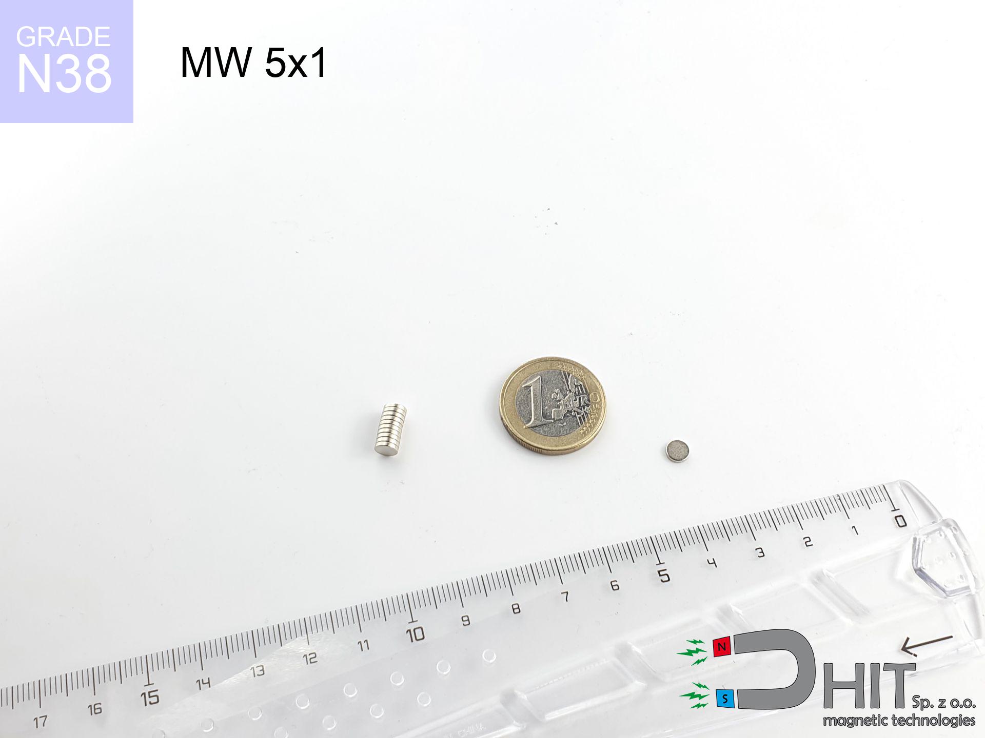
MW 5x1 / N38 - cylindrical magnet
cylindrical magnet
Catalog no 010082
GTIN/EAN: 5906301810810
Diameter Ø
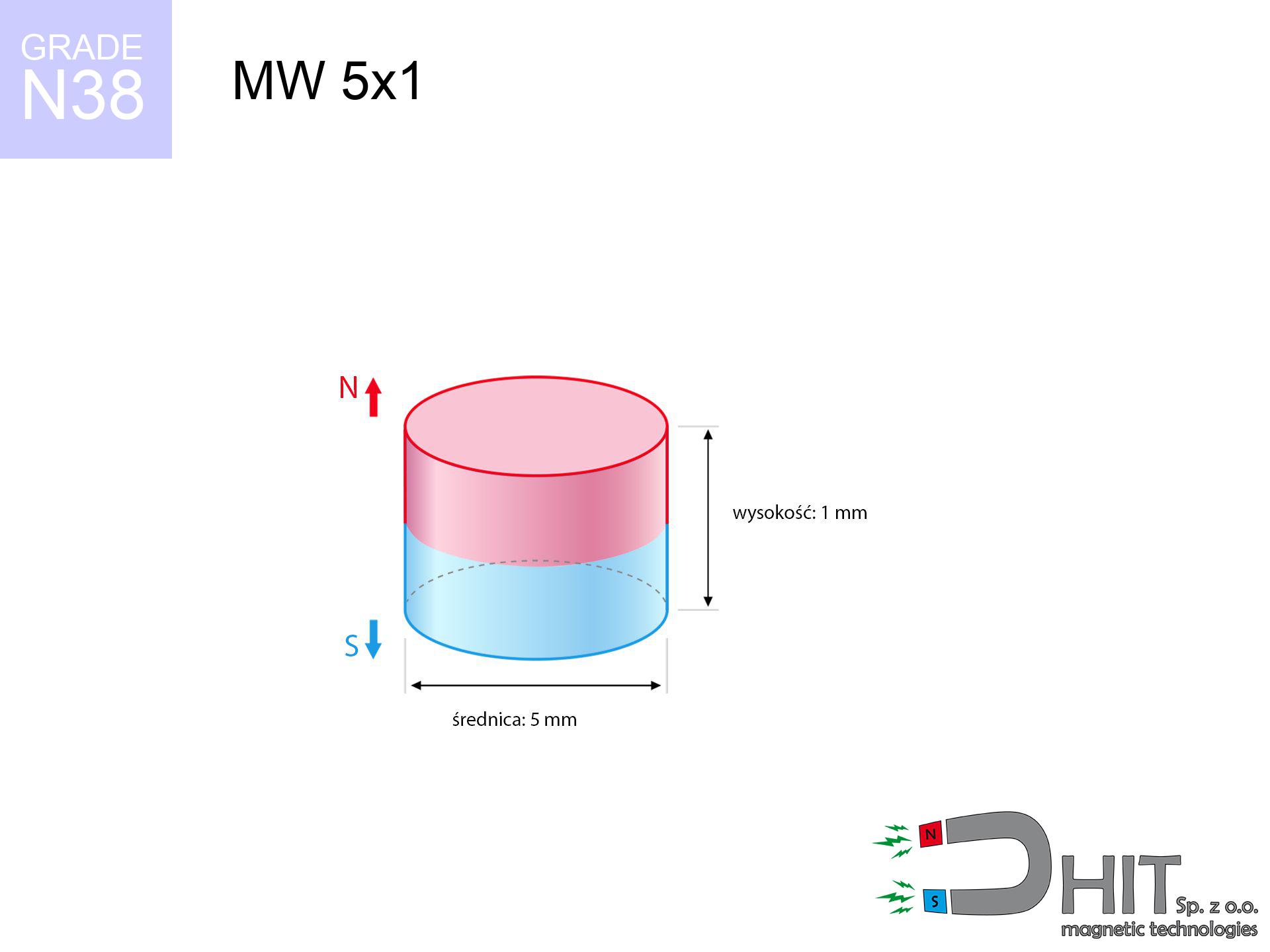
5 mm [±0,1 mm]
Height
1 mm [±0,1 mm]
Weight
0.15 g
Magnetization Direction
↑ axial
Load capacity
0.32 kg / 3.12 N
Magnetic Induction
229.95 mT / 2300 Gs
Coating
[NiCuNi] Nickel
0.1845 ZŁ with VAT / pcs + price for transport
0.1500 ZŁ net + 23% VAT / pcs
bulk discounts:
Need more?
Call us
+48 22 499 98 98
or contact us via
inquiry form
our website.
Lifting power and form of a magnet can be reviewed using our
magnetic mass calculator.
Order by 14:00 and we’ll ship today!
Detailed specification - MW 5x1 / N38 - cylindrical magnet
Specification / characteristics - MW 5x1 / N38 - cylindrical magnet
| properties | values |
|---|---|
| Cat. no. | 010082 |
| GTIN/EAN | 5906301810810 |
| Production/Distribution | Dhit sp. z o.o. |
| Country of origin | Poland / China / Germany |
| Customs code | 85059029 |
| Diameter Ø | 5 mm [±0,1 mm] |
| Height | 1 mm [±0,1 mm] |
| Weight | 0.15 g |
| Magnetization Direction | ↑ axial |
| Load capacity ~ ? | 0.32 kg / 3.12 N |
| Magnetic Induction ~ ? | 229.95 mT / 2300 Gs |
| Coating | [NiCuNi] Nickel |
| Manufacturing Tolerance | ±0.1 mm |
Magnetic properties of material N38
| properties | values | units |
|---|---|---|
| remenance Br [min. - max.] ? | 12.2-12.6 | kGs |
| remenance Br [min. - max.] ? | 1220-1260 | mT |
| coercivity bHc ? | 10.8-11.5 | kOe |
| coercivity bHc ? | 860-915 | kA/m |
| actual internal force iHc | ≥ 12 | kOe |
| actual internal force iHc | ≥ 955 | kA/m |
| energy density [min. - max.] ? | 36-38 | BH max MGOe |
| energy density [min. - max.] ? | 287-303 | BH max KJ/m |
| max. temperature ? | ≤ 80 | °C |
Physical properties of sintered neodymium magnets Nd2Fe14B at 20°C
| properties | values | units |
|---|---|---|
| Vickers hardness | ≥550 | Hv |
| Density | ≥7.4 | g/cm3 |
| Curie Temperature TC | 312 - 380 | °C |
| Curie Temperature TF | 593 - 716 | °F |
| Specific resistance | 150 | μΩ⋅cm |
| Bending strength | 250 | MPa |
| Compressive strength | 1000~1100 | MPa |
| Thermal expansion parallel (∥) to orientation (M) | (3-4) x 10-6 | °C-1 |
| Thermal expansion perpendicular (⊥) to orientation (M) | -(1-3) x 10-6 | °C-1 |
| Young's modulus | 1.7 x 10⁴ | kg/mm² |
Technical modeling of the assembly - report
These information are the outcome of a physical simulation. Values are based on models for the class Nd2Fe14B. Operational performance may deviate from the simulation results. Treat these data as a reference point for designers.
Table 1: Static pull force (force vs gap) - interaction chart
MW 5x1 / N38
| Distance (mm) | Induction (Gauss) / mT | Pull Force (kg/lbs/g/N) | Risk Status |
|---|---|---|---|
| 0 mm |
2298 Gs
229.8 mT
|
0.32 kg / 0.71 pounds
320.0 g / 3.1 N
|
weak grip |
| 1 mm |
1570 Gs
157.0 mT
|
0.15 kg / 0.33 pounds
149.5 g / 1.5 N
|
weak grip |
| 2 mm |
890 Gs
89.0 mT
|
0.05 kg / 0.11 pounds
48.0 g / 0.5 N
|
weak grip |
| 3 mm |
495 Gs
49.5 mT
|
0.01 kg / 0.03 pounds
14.8 g / 0.1 N
|
weak grip |
| 5 mm |
178 Gs
17.8 mT
|
0.00 kg / 0.00 pounds
1.9 g / 0.0 N
|
weak grip |
| 10 mm |
31 Gs
3.1 mT
|
0.00 kg / 0.00 pounds
0.1 g / 0.0 N
|
weak grip |
| 15 mm |
10 Gs
1.0 mT
|
0.00 kg / 0.00 pounds
0.0 g / 0.0 N
|
weak grip |
| 20 mm |
4 Gs
0.4 mT
|
0.00 kg / 0.00 pounds
0.0 g / 0.0 N
|
weak grip |
| 30 mm |
1 Gs
0.1 mT
|
0.00 kg / 0.00 pounds
0.0 g / 0.0 N
|
weak grip |
| 50 mm |
0 Gs
0.0 mT
|
0.00 kg / 0.00 pounds
0.0 g / 0.0 N
|
weak grip |
Table 2: Vertical capacity (wall)
MW 5x1 / N38
| Distance (mm) | Friction coefficient | Pull Force (kg/lbs/g/N) |
|---|---|---|
| 0 mm | Stal (~0.2) |
0.06 kg / 0.14 pounds
64.0 g / 0.6 N
|
| 1 mm | Stal (~0.2) |
0.03 kg / 0.07 pounds
30.0 g / 0.3 N
|
| 2 mm | Stal (~0.2) |
0.01 kg / 0.02 pounds
10.0 g / 0.1 N
|
| 3 mm | Stal (~0.2) |
0.00 kg / 0.00 pounds
2.0 g / 0.0 N
|
| 5 mm | Stal (~0.2) |
0.00 kg / 0.00 pounds
0.0 g / 0.0 N
|
| 10 mm | Stal (~0.2) |
0.00 kg / 0.00 pounds
0.0 g / 0.0 N
|
| 15 mm | Stal (~0.2) |
0.00 kg / 0.00 pounds
0.0 g / 0.0 N
|
| 20 mm | Stal (~0.2) |
0.00 kg / 0.00 pounds
0.0 g / 0.0 N
|
| 30 mm | Stal (~0.2) |
0.00 kg / 0.00 pounds
0.0 g / 0.0 N
|
| 50 mm | Stal (~0.2) |
0.00 kg / 0.00 pounds
0.0 g / 0.0 N
|
Table 3: Vertical assembly (shearing) - behavior on slippery surfaces
MW 5x1 / N38
| Surface type | Friction coefficient / % Mocy | Max load (kg/lbs/g/N) |
|---|---|---|
| Raw steel |
µ = 0.3
30% Nominalnej Siły
|
0.10 kg / 0.21 pounds
96.0 g / 0.9 N
|
| Painted steel (standard) |
µ = 0.2
20% Nominalnej Siły
|
0.06 kg / 0.14 pounds
64.0 g / 0.6 N
|
| Oily/slippery steel |
µ = 0.1
10% Nominalnej Siły
|
0.03 kg / 0.07 pounds
32.0 g / 0.3 N
|
| Magnet with anti-slip rubber |
µ = 0.5
50% Nominalnej Siły
|
0.16 kg / 0.35 pounds
160.0 g / 1.6 N
|
Table 4: Steel thickness (saturation) - sheet metal selection
MW 5x1 / N38
| Steel thickness (mm) | % power | Real pull force (kg/lbs/g/N) |
|---|---|---|
| 0.5 mm |
|
0.03 kg / 0.07 pounds
32.0 g / 0.3 N
|
| 1 mm |
|
0.08 kg / 0.18 pounds
80.0 g / 0.8 N
|
| 2 mm |
|
0.16 kg / 0.35 pounds
160.0 g / 1.6 N
|
| 3 mm |
|
0.24 kg / 0.53 pounds
240.0 g / 2.4 N
|
| 5 mm |
|
0.32 kg / 0.71 pounds
320.0 g / 3.1 N
|
| 10 mm |
|
0.32 kg / 0.71 pounds
320.0 g / 3.1 N
|
| 11 mm |
|
0.32 kg / 0.71 pounds
320.0 g / 3.1 N
|
| 12 mm |
|
0.32 kg / 0.71 pounds
320.0 g / 3.1 N
|
Table 5: Working in heat (stability) - power drop
MW 5x1 / N38
| Ambient temp. (°C) | Power loss | Remaining pull (kg/lbs/g/N) | Status |
|---|---|---|---|
| 20 °C | 0.0% |
0.32 kg / 0.71 pounds
320.0 g / 3.1 N
|
OK |
| 40 °C | -2.2% |
0.31 kg / 0.69 pounds
313.0 g / 3.1 N
|
OK |
| 60 °C | -4.4% |
0.31 kg / 0.67 pounds
305.9 g / 3.0 N
|
|
| 80 °C | -6.6% |
0.30 kg / 0.66 pounds
298.9 g / 2.9 N
|
|
| 100 °C | -28.8% |
0.23 kg / 0.50 pounds
227.8 g / 2.2 N
|
Table 6: Two magnets (repulsion) - field range
MW 5x1 / N38
| Gap (mm) | Attraction (kg/lbs) (N-S) | Shear Force (kg/lbs/g/N) | Repulsion (kg/lbs) (N-N) |
|---|---|---|---|
| 0 mm |
0.64 kg / 1.41 pounds
3 860 Gs
|
0.10 kg / 0.21 pounds
96 g / 0.9 N
|
N/A |
| 1 mm |
0.47 kg / 1.04 pounds
3 948 Gs
|
0.07 kg / 0.16 pounds
71 g / 0.7 N
|
0.42 kg / 0.94 pounds
~0 Gs
|
| 2 mm |
0.30 kg / 0.66 pounds
3 141 Gs
|
0.04 kg / 0.10 pounds
45 g / 0.4 N
|
0.27 kg / 0.59 pounds
~0 Gs
|
| 3 mm |
0.17 kg / 0.38 pounds
2 388 Gs
|
0.03 kg / 0.06 pounds
26 g / 0.3 N
|
0.16 kg / 0.34 pounds
~0 Gs
|
| 5 mm |
0.05 kg / 0.12 pounds
1 322 Gs
|
0.01 kg / 0.02 pounds
8 g / 0.1 N
|
0.05 kg / 0.10 pounds
~0 Gs
|
| 10 mm |
0.00 kg / 0.01 pounds
355 Gs
|
0.00 kg / 0.00 pounds
1 g / 0.0 N
|
0.00 kg / 0.00 pounds
~0 Gs
|
| 20 mm |
0.00 kg / 0.00 pounds
62 Gs
|
0.00 kg / 0.00 pounds
0 g / 0.0 N
|
0.00 kg / 0.00 pounds
~0 Gs
|
| 50 mm |
0.00 kg / 0.00 pounds
5 Gs
|
0.00 kg / 0.00 pounds
0 g / 0.0 N
|
0.00 kg / 0.00 pounds
~0 Gs
|
| 60 mm |
0.00 kg / 0.00 pounds
3 Gs
|
0.00 kg / 0.00 pounds
0 g / 0.0 N
|
0.00 kg / 0.00 pounds
~0 Gs
|
| 70 mm |
0.00 kg / 0.00 pounds
2 Gs
|
0.00 kg / 0.00 pounds
0 g / 0.0 N
|
0.00 kg / 0.00 pounds
~0 Gs
|
| 80 mm |
0.00 kg / 0.00 pounds
1 Gs
|
0.00 kg / 0.00 pounds
0 g / 0.0 N
|
0.00 kg / 0.00 pounds
~0 Gs
|
| 90 mm |
0.00 kg / 0.00 pounds
1 Gs
|
0.00 kg / 0.00 pounds
0 g / 0.0 N
|
0.00 kg / 0.00 pounds
~0 Gs
|
| 100 mm |
0.00 kg / 0.00 pounds
1 Gs
|
0.00 kg / 0.00 pounds
0 g / 0.0 N
|
0.00 kg / 0.00 pounds
~0 Gs
|
Table 7: Protective zones (implants) - precautionary measures
MW 5x1 / N38
| Object / Device | Limit (Gauss) / mT | Safe distance |
|---|---|---|
| Pacemaker | 5 Gs (0.5 mT) | 2.0 cm |
| Hearing aid | 10 Gs (1.0 mT) | 2.0 cm |
| Timepiece | 20 Gs (2.0 mT) | 1.5 cm |
| Phone / Smartphone | 40 Gs (4.0 mT) | 1.0 cm |
| Remote | 50 Gs (5.0 mT) | 1.0 cm |
| Payment card | 400 Gs (40.0 mT) | 0.5 cm |
| HDD hard drive | 600 Gs (60.0 mT) | 0.5 cm |
Table 8: Impact energy (kinetic energy) - collision effects
MW 5x1 / N38
| Start from (mm) | Speed (km/h) | Energy (J) | Predicted outcome |
|---|---|---|---|
| 10 mm |
46.59 km/h
(12.94 m/s)
|
0.01 J | |
| 30 mm |
80.68 km/h
(22.41 m/s)
|
0.04 J | |
| 50 mm |
104.16 km/h
(28.93 m/s)
|
0.06 J | |
| 100 mm |
147.30 km/h
(40.92 m/s)
|
0.13 J |
Table 9: Coating parameters (durability)
MW 5x1 / N38
| Technical parameter | Value / Description |
|---|---|
| Coating type | [NiCuNi] Nickel |
| Layer structure | Nickel - Copper - Nickel |
| Layer thickness | 10-20 µm |
| Salt spray test (SST) ? | 24 h |
| Recommended environment | Indoors only (dry) |
Table 10: Construction data (Pc)
MW 5x1 / N38
| Parameter | Value | SI Unit / Description |
|---|---|---|
| Magnetic Flux | 524 Mx | 5.2 µWb |
| Pc Coefficient | 0.29 | Low (Flat) |
Table 11: Submerged application
MW 5x1 / N38
| Environment | Effective steel pull | Effect |
|---|---|---|
| Air (land) | 0.32 kg | Standard |
| Water (riverbed) |
0.37 kg
(+0.05 kg buoyancy gain)
|
+14.5% |
1. Sliding resistance
*Caution: On a vertical surface, the magnet retains just approx. 20-30% of its max power.
2. Steel thickness impact
*Thin metal sheet (e.g. 0.5mm PC case) significantly weakens the holding force.
3. Temperature resistance
*For N38 grade, the safety limit is 80°C.
4. Demagnetization curve and operating point (B-H)
chart generated for the permeance coefficient Pc (Permeance Coefficient) = 0.29
This simulation demonstrates the magnetic stability of the selected magnet under specific geometric conditions. The solid red line represents the demagnetization curve (material potential), while the dashed blue line is the load line based on the magnet's geometry. The Pc (Permeance Coefficient), also known as the load line slope, is a dimensionless value that describes the relationship between the magnet's shape and its magnetic stability. The intersection of these two lines (the black dot) is the operating point — it determines the actual magnetic flux density generated by the magnet in this specific configuration. A higher Pc value means the magnet is more 'slender' (tall relative to its area), resulting in a higher operating point and better resistance to irreversible demagnetization caused by external fields or temperature. A value of 0.42 is relatively low (typical for flat magnets), meaning the operating point is closer to the 'knee' of the curve — caution is advised when operating at temperatures near the maximum limit to avoid strength loss.
Elemental analysis
| iron (Fe) | 64% – 68% |
| neodymium (Nd) | 29% – 32% |
| boron (B) | 1.1% – 1.2% |
| dysprosium (Dy) | 0.5% – 2.0% |
| coating (Ni-Cu-Ni) | < 0.05% |
Ecology and recycling (GPSR)
| recyclability (EoL) | 100% |
| recycled raw materials | ~10% (pre-cons) |
| carbon footprint | low / zredukowany |
| waste code (EWC) | 16 02 16 |
Check out more offers

![UMGZ 16x13x5 [M4] GZ / N38 - magnetic holder external thread](https://cdn3.dhit.pl/graphics/products/um-16x13x5-m4-gz-cor.jpg "UMGZ 16x13x5 [M4] GZ / N38 - magnetic holder external thread")


Pros as well as cons of Nd2Fe14B magnets.
Strengths
- They retain magnetic properties for around ten years – the loss is just ~1% (in theory),
- They are resistant to demagnetization induced by external field influence,
- By covering with a lustrous coating of nickel, the element presents an nice look,
- Magnetic induction on the top side of the magnet turns out to be exceptional,
- Made from properly selected components, these magnets show impressive resistance to high heat, enabling them to function (depending on their shape) at temperatures up to 230°C and above...
- Possibility of exact modeling as well as modifying to specific requirements,
- Universal use in electronics industry – they are used in computer drives, electric motors, advanced medical instruments, as well as other advanced devices.
- Compactness – despite small sizes they offer powerful magnetic field, making them ideal for precision applications
Disadvantages
- To avoid cracks under impact, we suggest using special steel housings. Such a solution protects the magnet and simultaneously increases its durability.
- Neodymium magnets lose strength when exposed to high temperatures. After reaching 80°C, many of them experience permanent weakening of power (a factor is the shape as well as dimensions of the magnet). We offer magnets specially adapted to work at temperatures up to 230°C marked [AH], which are very resistant to heat
- Magnets exposed to a humid environment can rust. Therefore when using outdoors, we suggest using water-impermeable magnets made of rubber, plastic or other material resistant to moisture
- Due to limitations in creating threads and complicated shapes in magnets, we recommend using cover - magnetic holder.
- Possible danger related to microscopic parts of magnets pose a threat, in case of ingestion, which gains importance in the context of child health protection. It is also worth noting that small elements of these magnets can disrupt the diagnostic process medical when they are in the body.
- With mass production the cost of neodymium magnets can be a barrier,
Holding force characteristics
Highest magnetic holding force – what contributes to it?
- with the use of a yoke made of special test steel, guaranteeing full magnetic saturation
- with a thickness of at least 10 mm
- with an ground contact surface
- with direct contact (without coatings)
- during detachment in a direction perpendicular to the mounting surface
- at conditions approx. 20°C
Impact of factors on magnetic holding capacity in practice
- Gap between magnet and steel – even a fraction of a millimeter of separation (caused e.g. by veneer or unevenness) drastically reduces the pulling force, often by half at just 0.5 mm.
- Force direction – remember that the magnet holds strongest perpendicularly. Under shear forces, the holding force drops drastically, often to levels of 20-30% of the maximum value.
- Wall thickness – thin material does not allow full use of the magnet. Magnetic flux passes through the material instead of converting into lifting capacity.
- Metal type – different alloys attracts identically. High carbon content worsen the interaction with the magnet.
- Smoothness – ideal contact is obtained only on polished steel. Rough texture create air cushions, weakening the magnet.
- Temperature influence – high temperature weakens pulling force. Too high temperature can permanently demagnetize the magnet.
Holding force was measured on the plate surface of 20 mm thickness, when the force acted perpendicularly, in contrast under parallel forces the load capacity is reduced by as much as fivefold. Additionally, even a slight gap between the magnet’s surface and the plate decreases the holding force.
H&S for magnets
Bone fractures
Protect your hands. Two powerful magnets will join immediately with a force of several hundred kilograms, crushing anything in their path. Be careful!
Protective goggles
NdFeB magnets are sintered ceramics, meaning they are very brittle. Impact of two magnets leads to them cracking into small pieces.
Operating temperature
Standard neodymium magnets (N-type) undergo demagnetization when the temperature surpasses 80°C. This process is irreversible.
Data carriers
Do not bring magnets near a purse, computer, or TV. The magnetic field can permanently damage these devices and erase data from cards.
Medical interference
Medical warning: Strong magnets can turn off pacemakers and defibrillators. Stay away if you have medical devices.
Precision electronics
An intense magnetic field negatively affects the functioning of magnetometers in smartphones and navigation systems. Keep magnets close to a smartphone to prevent breaking the sensors.
Keep away from children
Adult use only. Small elements can be swallowed, causing serious injuries. Keep out of reach of children and animals.
Combustion hazard
Mechanical processing of NdFeB material carries a risk of fire hazard. Neodymium dust reacts violently with oxygen and is hard to extinguish.
Conscious usage
Use magnets with awareness. Their huge power can surprise even experienced users. Be vigilant and do not underestimate their force.
Sensitization to coating
Nickel alert: The Ni-Cu-Ni coating contains nickel. If redness happens, immediately stop handling magnets and use protective gear.
Tabela kosztu i czasu dostawy
Płatność przed wysyłką:

GLS kurier
Przesyłka będzie u Ciebie za 2-3 dni
14.99 ZŁ

InPost Paczkomaty 24/7
Przesyłka będzie u Ciebie za 1-2 dni
12.30 ZŁ
Płatność przy odbiorze (pobranie):
GLS kurier
Przesyłka będzie u Ciebie za 1-2 dni
23.00 ZŁ
Rate the product
Your rating