
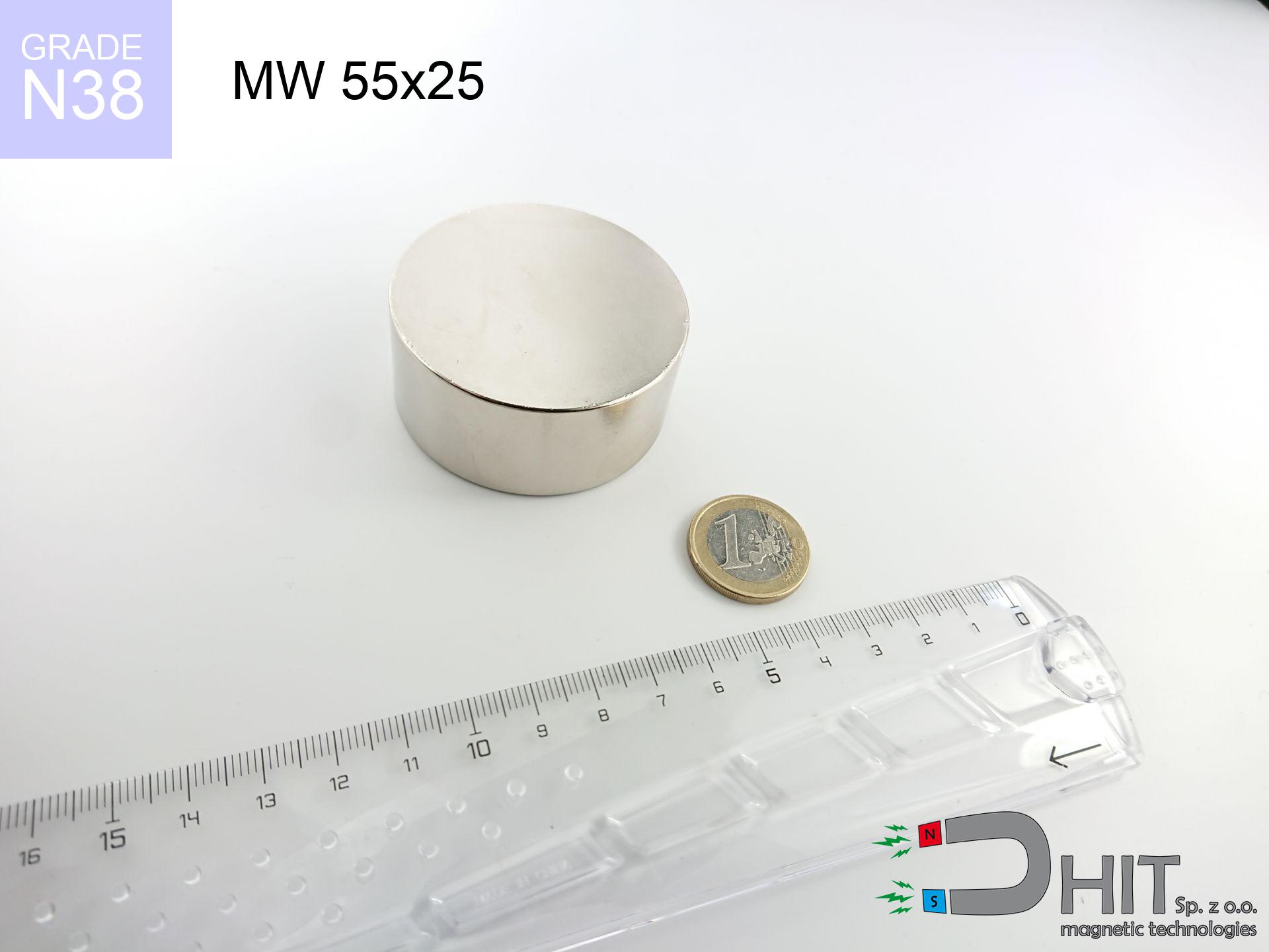
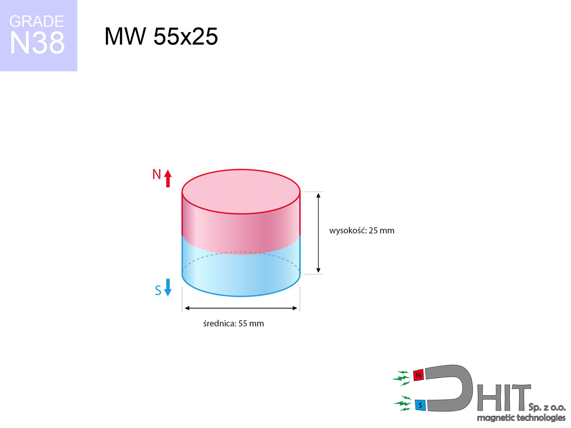
MW 55x25 / N38 - cylindrical magnet
cylindrical magnet
Catalog no 010081
GTIN/EAN: 5906301810803
Diameter Ø
55 mm [±0,1 mm]
Height
25 mm [±0,1 mm]
Weight
445.47 g
Magnetization Direction
↑ axial
Load capacity
92.25 kg / 904.94 N
Magnetic Induction
416.97 mT / 4170 Gs
Coating
[NiCuNi] Nickel
154.21 ZŁ with VAT / pcs + price for transport
125.37 ZŁ net + 23% VAT / pcs
bulk discounts:
Need more?
Call us now
+48 22 499 98 98
alternatively drop us a message by means of
contact form
the contact form page.
Lifting power along with appearance of magnetic components can be analyzed using our
magnetic calculator.
Order by 14:00 and we’ll ship today!
Technical details - MW 55x25 / N38 - cylindrical magnet
Specification / characteristics - MW 55x25 / N38 - cylindrical magnet
| properties | values |
|---|---|
| Cat. no. | 010081 |
| GTIN/EAN | 5906301810803 |
| Production/Distribution | Dhit sp. z o.o. |
| Country of origin | Poland / China / Germany |
| Customs code | 85059029 |
| Diameter Ø | 55 mm [±0,1 mm] |
| Height | 25 mm [±0,1 mm] |
| Weight | 445.47 g |
| Magnetization Direction | ↑ axial |
| Load capacity ~ ? | 92.25 kg / 904.94 N |
| Magnetic Induction ~ ? | 416.97 mT / 4170 Gs |
| Coating | [NiCuNi] Nickel |
| Manufacturing Tolerance | ±0.1 mm |
Magnetic properties of material N38
| properties | values | units |
|---|---|---|
| remenance Br [min. - max.] ? | 12.2-12.6 | kGs |
| remenance Br [min. - max.] ? | 1220-1260 | mT |
| coercivity bHc ? | 10.8-11.5 | kOe |
| coercivity bHc ? | 860-915 | kA/m |
| actual internal force iHc | ≥ 12 | kOe |
| actual internal force iHc | ≥ 955 | kA/m |
| energy density [min. - max.] ? | 36-38 | BH max MGOe |
| energy density [min. - max.] ? | 287-303 | BH max KJ/m |
| max. temperature ? | ≤ 80 | °C |
Physical properties of sintered neodymium magnets Nd2Fe14B at 20°C
| properties | values | units |
|---|---|---|
| Vickers hardness | ≥550 | Hv |
| Density | ≥7.4 | g/cm3 |
| Curie Temperature TC | 312 - 380 | °C |
| Curie Temperature TF | 593 - 716 | °F |
| Specific resistance | 150 | μΩ⋅cm |
| Bending strength | 250 | MPa |
| Compressive strength | 1000~1100 | MPa |
| Thermal expansion parallel (∥) to orientation (M) | (3-4) x 10-6 | °C-1 |
| Thermal expansion perpendicular (⊥) to orientation (M) | -(1-3) x 10-6 | °C-1 |
| Young's modulus | 1.7 x 10⁴ | kg/mm² |
Engineering analysis of the product - technical parameters
These values are the outcome of a mathematical calculation. Results rely on models for the class Nd2Fe14B. Operational conditions might slightly differ from theoretical values. Please consider these data as a preliminary roadmap when designing systems.
Table 1: Static pull force (pull vs gap) - power drop
MW 55x25 / N38
| Distance (mm) | Induction (Gauss) / mT | Pull Force (kg/lbs/g/N) | Risk Status |
|---|---|---|---|
| 0 mm |
4169 Gs
416.9 mT
|
92.25 kg / 203.38 lbs
92250.0 g / 905.0 N
|
dangerous! |
| 1 mm |
4034 Gs
403.4 mT
|
86.37 kg / 190.41 lbs
86369.8 g / 847.3 N
|
dangerous! |
| 2 mm |
3894 Gs
389.4 mT
|
80.47 kg / 177.41 lbs
80469.7 g / 789.4 N
|
dangerous! |
| 3 mm |
3751 Gs
375.1 mT
|
74.67 kg / 164.62 lbs
74670.6 g / 732.5 N
|
dangerous! |
| 5 mm |
3461 Gs
346.1 mT
|
63.58 kg / 140.17 lbs
63580.6 g / 623.7 N
|
dangerous! |
| 10 mm |
2756 Gs
275.6 mT
|
40.32 kg / 88.89 lbs
40320.8 g / 395.5 N
|
dangerous! |
| 15 mm |
2140 Gs
214.0 mT
|
24.31 kg / 53.59 lbs
24308.3 g / 238.5 N
|
dangerous! |
| 20 mm |
1644 Gs
164.4 mT
|
14.34 kg / 31.61 lbs
14338.1 g / 140.7 N
|
dangerous! |
| 30 mm |
975 Gs
97.5 mT
|
5.05 kg / 11.12 lbs
5046.0 g / 49.5 N
|
medium risk |
| 50 mm |
388 Gs
38.8 mT
|
0.80 kg / 1.77 lbs
801.0 g / 7.9 N
|
weak grip |
Table 2: Sliding load (wall)
MW 55x25 / N38
| Distance (mm) | Friction coefficient | Pull Force (kg/lbs/g/N) |
|---|---|---|
| 0 mm | Stal (~0.2) |
18.45 kg / 40.68 lbs
18450.0 g / 181.0 N
|
| 1 mm | Stal (~0.2) |
17.27 kg / 38.08 lbs
17274.0 g / 169.5 N
|
| 2 mm | Stal (~0.2) |
16.09 kg / 35.48 lbs
16094.0 g / 157.9 N
|
| 3 mm | Stal (~0.2) |
14.93 kg / 32.92 lbs
14934.0 g / 146.5 N
|
| 5 mm | Stal (~0.2) |
12.72 kg / 28.03 lbs
12716.0 g / 124.7 N
|
| 10 mm | Stal (~0.2) |
8.06 kg / 17.78 lbs
8064.0 g / 79.1 N
|
| 15 mm | Stal (~0.2) |
4.86 kg / 10.72 lbs
4862.0 g / 47.7 N
|
| 20 mm | Stal (~0.2) |
2.87 kg / 6.32 lbs
2868.0 g / 28.1 N
|
| 30 mm | Stal (~0.2) |
1.01 kg / 2.23 lbs
1010.0 g / 9.9 N
|
| 50 mm | Stal (~0.2) |
0.16 kg / 0.35 lbs
160.0 g / 1.6 N
|
Table 3: Wall mounting (shearing) - vertical pull
MW 55x25 / N38
| Surface type | Friction coefficient / % Mocy | Max load (kg/lbs/g/N) |
|---|---|---|
| Raw steel |
µ = 0.3
30% Nominalnej Siły
|
27.68 kg / 61.01 lbs
27675.0 g / 271.5 N
|
| Painted steel (standard) |
µ = 0.2
20% Nominalnej Siły
|
18.45 kg / 40.68 lbs
18450.0 g / 181.0 N
|
| Oily/slippery steel |
µ = 0.1
10% Nominalnej Siły
|
9.23 kg / 20.34 lbs
9225.0 g / 90.5 N
|
| Magnet with anti-slip rubber |
µ = 0.5
50% Nominalnej Siły
|
46.13 kg / 101.69 lbs
46125.0 g / 452.5 N
|
Table 4: Steel thickness (substrate influence) - sheet metal selection
MW 55x25 / N38
| Steel thickness (mm) | % power | Real pull force (kg/lbs/g/N) |
|---|---|---|
| 0.5 mm |
|
3.08 kg / 6.78 lbs
3075.0 g / 30.2 N
|
| 1 mm |
|
7.69 kg / 16.95 lbs
7687.5 g / 75.4 N
|
| 2 mm |
|
15.37 kg / 33.90 lbs
15375.0 g / 150.8 N
|
| 3 mm |
|
23.06 kg / 50.84 lbs
23062.5 g / 226.2 N
|
| 5 mm |
|
38.44 kg / 84.74 lbs
38437.5 g / 377.1 N
|
| 10 mm |
|
76.88 kg / 169.48 lbs
76875.0 g / 754.1 N
|
| 11 mm |
|
84.56 kg / 186.43 lbs
84562.5 g / 829.6 N
|
| 12 mm |
|
92.25 kg / 203.38 lbs
92250.0 g / 905.0 N
|
Table 5: Thermal resistance (material behavior) - power drop
MW 55x25 / N38
| Ambient temp. (°C) | Power loss | Remaining pull (kg/lbs/g/N) | Status |
|---|---|---|---|
| 20 °C | 0.0% |
92.25 kg / 203.38 lbs
92250.0 g / 905.0 N
|
OK |
| 40 °C | -2.2% |
90.22 kg / 198.90 lbs
90220.5 g / 885.1 N
|
OK |
| 60 °C | -4.4% |
88.19 kg / 194.43 lbs
88191.0 g / 865.2 N
|
|
| 80 °C | -6.6% |
86.16 kg / 189.95 lbs
86161.5 g / 845.2 N
|
|
| 100 °C | -28.8% |
65.68 kg / 144.80 lbs
65682.0 g / 644.3 N
|
Table 6: Magnet-Magnet interaction (repulsion) - field collision
MW 55x25 / N38
| Gap (mm) | Attraction (kg/lbs) (N-S) | Sliding Force (kg/lbs/g/N) | Repulsion (kg/lbs) (N-N) |
|---|---|---|---|
| 0 mm |
254.60 kg / 561.30 lbs
5 431 Gs
|
38.19 kg / 84.20 lbs
38190 g / 374.6 N
|
N/A |
| 1 mm |
246.57 kg / 543.59 lbs
8 206 Gs
|
36.99 kg / 81.54 lbs
36985 g / 362.8 N
|
221.91 kg / 489.23 lbs
~0 Gs
|
| 2 mm |
238.37 kg / 525.52 lbs
8 068 Gs
|
35.76 kg / 78.83 lbs
35756 g / 350.8 N
|
214.54 kg / 472.97 lbs
~0 Gs
|
| 3 mm |
230.21 kg / 507.52 lbs
7 929 Gs
|
34.53 kg / 76.13 lbs
34531 g / 338.7 N
|
207.19 kg / 456.77 lbs
~0 Gs
|
| 5 mm |
214.04 kg / 471.88 lbs
7 645 Gs
|
32.11 kg / 70.78 lbs
32106 g / 315.0 N
|
192.64 kg / 424.69 lbs
~0 Gs
|
| 10 mm |
175.48 kg / 386.86 lbs
6 923 Gs
|
26.32 kg / 58.03 lbs
26322 g / 258.2 N
|
157.93 kg / 348.17 lbs
~0 Gs
|
| 20 mm |
111.28 kg / 245.33 lbs
5 513 Gs
|
16.69 kg / 36.80 lbs
16692 g / 163.8 N
|
100.15 kg / 220.80 lbs
~0 Gs
|
| 50 mm |
23.33 kg / 51.43 lbs
2 524 Gs
|
3.50 kg / 7.71 lbs
3499 g / 34.3 N
|
20.99 kg / 46.28 lbs
~0 Gs
|
| 60 mm |
13.93 kg / 30.70 lbs
1 950 Gs
|
2.09 kg / 4.61 lbs
2089 g / 20.5 N
|
12.53 kg / 27.63 lbs
~0 Gs
|
| 70 mm |
8.48 kg / 18.70 lbs
1 522 Gs
|
1.27 kg / 2.81 lbs
1272 g / 12.5 N
|
7.63 kg / 16.83 lbs
~0 Gs
|
| 80 mm |
5.29 kg / 11.66 lbs
1 202 Gs
|
0.79 kg / 1.75 lbs
793 g / 7.8 N
|
4.76 kg / 10.50 lbs
~0 Gs
|
| 90 mm |
3.38 kg / 7.45 lbs
961 Gs
|
0.51 kg / 1.12 lbs
507 g / 5.0 N
|
3.04 kg / 6.70 lbs
~0 Gs
|
| 100 mm |
2.21 kg / 4.87 lbs
777 Gs
|
0.33 kg / 0.73 lbs
332 g / 3.3 N
|
1.99 kg / 4.39 lbs
~0 Gs
|
Table 7: Protective zones (electronics) - warnings
MW 55x25 / N38
| Object / Device | Limit (Gauss) / mT | Safe distance |
|---|---|---|
| Pacemaker | 5 Gs (0.5 mT) | 27.5 cm |
| Hearing aid | 10 Gs (1.0 mT) | 21.5 cm |
| Mechanical watch | 20 Gs (2.0 mT) | 17.0 cm |
| Mobile device | 40 Gs (4.0 mT) | 13.0 cm |
| Remote | 50 Gs (5.0 mT) | 12.0 cm |
| Payment card | 400 Gs (40.0 mT) | 5.0 cm |
| HDD hard drive | 600 Gs (60.0 mT) | 4.5 cm |
Table 8: Collisions (cracking risk) - warning
MW 55x25 / N38
| Start from (mm) | Speed (km/h) | Energy (J) | Predicted outcome |
|---|---|---|---|
| 10 mm |
18.05 km/h
(5.01 m/s)
|
5.60 J | |
| 30 mm |
25.98 km/h
(7.22 m/s)
|
11.60 J | |
| 50 mm |
32.63 km/h
(9.06 m/s)
|
18.30 J | |
| 100 mm |
45.90 km/h
(12.75 m/s)
|
36.21 J |
Table 9: Anti-corrosion coating durability
MW 55x25 / N38
| Technical parameter | Value / Description |
|---|---|
| Coating type | [NiCuNi] Nickel |
| Layer structure | Nickel - Copper - Nickel |
| Layer thickness | 10-20 µm |
| Salt spray test (SST) ? | 24 h |
| Recommended environment | Indoors only (dry) |
Table 10: Electrical data (Flux)
MW 55x25 / N38
| Parameter | Value | SI Unit / Description |
|---|---|---|
| Magnetic Flux | 101 075 Mx | 1010.7 µWb |
| Pc Coefficient | 0.55 | Low (Flat) |
Table 11: Physics of underwater searching
MW 55x25 / N38
| Environment | Effective steel pull | Effect |
|---|---|---|
| Air (land) | 92.25 kg | Standard |
| Water (riverbed) |
105.63 kg
(+13.38 kg buoyancy gain)
|
+14.5% |
1. Wall mount (shear)
*Note: On a vertical wall, the magnet holds merely a fraction of its max power.
2. Plate thickness effect
*Thin metal sheet (e.g. computer case) significantly weakens the holding force.
3. Power loss vs temp
*For N38 material, the critical limit is 80°C.
4. Demagnetization curve and operating point (B-H)
chart generated for the permeance coefficient Pc (Permeance Coefficient) = 0.55
This simulation demonstrates the magnetic stability of the selected magnet under specific geometric conditions. The solid red line represents the demagnetization curve (material potential), while the dashed blue line is the load line based on the magnet's geometry. The Pc (Permeance Coefficient), also known as the load line slope, is a dimensionless value that describes the relationship between the magnet's shape and its magnetic stability. The intersection of these two lines (the black dot) is the operating point — it determines the actual magnetic flux density generated by the magnet in this specific configuration. A higher Pc value means the magnet is more 'slender' (tall relative to its area), resulting in a higher operating point and better resistance to irreversible demagnetization caused by external fields or temperature. A value of 0.42 is relatively low (typical for flat magnets), meaning the operating point is closer to the 'knee' of the curve — caution is advised when operating at temperatures near the maximum limit to avoid strength loss.
Chemical composition
| iron (Fe) | 64% – 68% |
| neodymium (Nd) | 29% – 32% |
| boron (B) | 1.1% – 1.2% |
| dysprosium (Dy) | 0.5% – 2.0% |
| coating (Ni-Cu-Ni) | < 0.05% |
Ecology and recycling (GPSR)
| recyclability (EoL) | 100% |
| recycled raw materials | ~10% (pre-cons) |
| carbon footprint | low / zredukowany |
| waste code (EWC) | 16 02 16 |
View also proposals


![AM ucho [M10] - magnetic accessories](https://cdn3.dhit.pl/graphics/products/am-ucho-m10-tij.jpg "AM ucho [M10] - magnetic accessories")
Strengths and weaknesses of rare earth magnets.
Benefits
- They retain attractive force for almost 10 years – the loss is just ~1% (based on simulations),
- Neodymium magnets remain extremely resistant to magnetic field loss caused by magnetic disturbances,
- In other words, due to the metallic layer of silver, the element gains a professional look,
- Magnetic induction on the surface of the magnet remains impressive,
- Due to their durability and thermal resistance, neodymium magnets are capable of operate (depending on the shape) even at high temperatures reaching 230°C or more...
- In view of the ability of accurate shaping and adaptation to specialized needs, NdFeB magnets can be manufactured in a wide range of shapes and sizes, which expands the range of possible applications,
- Universal use in modern technologies – they serve a role in mass storage devices, brushless drives, precision medical tools, also modern systems.
- Relatively small size with high pulling force – neodymium magnets offer high power in tiny dimensions, which makes them useful in compact constructions
Cons
- At very strong impacts they can break, therefore we advise placing them in steel cases. A metal housing provides additional protection against damage, as well as increases the magnet's durability.
- Neodymium magnets lose strength when exposed to high temperatures. After reaching 80°C, many of them experience permanent weakening of strength (a factor is the shape and dimensions of the magnet). We offer magnets specially adapted to work at temperatures up to 230°C marked [AH], which are very resistant to heat
- When exposed to humidity, magnets usually rust. For applications outside, it is recommended to use protective magnets, such as those in rubber or plastics, which secure oxidation and corrosion.
- Limited ability of creating nuts in the magnet and complicated shapes - recommended is casing - mounting mechanism.
- Health risk related to microscopic parts of magnets are risky, in case of ingestion, which gains importance in the context of child safety. Additionally, small components of these magnets can complicate diagnosis medical in case of swallowing.
- High unit price – neodymium magnets are more expensive than other types of magnets (e.g. ferrite), which hinders application in large quantities
Holding force characteristics
Best holding force of the magnet in ideal parameters – what affects it?
- with the contact of a yoke made of special test steel, guaranteeing maximum field concentration
- with a thickness no less than 10 mm
- with a surface cleaned and smooth
- with direct contact (no impurities)
- under axial application of breakaway force (90-degree angle)
- at temperature room level
Determinants of lifting force in real conditions
- Distance – the presence of foreign body (paint, dirt, gap) interrupts the magnetic circuit, which reduces capacity rapidly (even by 50% at 0.5 mm).
- Load vector – highest force is obtained only during pulling at a 90° angle. The shear force of the magnet along the plate is usually many times smaller (approx. 1/5 of the lifting capacity).
- Element thickness – to utilize 100% power, the steel must be sufficiently thick. Paper-thin metal restricts the attraction force (the magnet "punches through" it).
- Chemical composition of the base – mild steel attracts best. Higher carbon content lower magnetic permeability and holding force.
- Base smoothness – the more even the plate, the larger the contact zone and stronger the hold. Unevenness creates an air distance.
- Temperature – temperature increase causes a temporary drop of force. It is worth remembering the thermal limit for a given model.
Holding force was measured on the plate surface of 20 mm thickness, when the force acted perpendicularly, in contrast under attempts to slide the magnet the load capacity is reduced by as much as fivefold. Moreover, even a minimal clearance between the magnet’s surface and the plate reduces the load capacity.
H&S for magnets
Crushing force
Risk of injury: The pulling power is so great that it can cause blood blisters, pinching, and even bone fractures. Protective gloves are recommended.
Fragile material
NdFeB magnets are sintered ceramics, which means they are very brittle. Collision of two magnets will cause them breaking into small pieces.
Phone sensors
Navigation devices and smartphones are highly sensitive to magnetism. Close proximity with a strong magnet can ruin the sensors in your phone.
Danger to the youngest
NdFeB magnets are not toys. Eating a few magnets may result in them pinching intestinal walls, which poses a critical condition and requires immediate surgery.
Magnetic media
Equipment safety: Strong magnets can damage data carriers and sensitive devices (pacemakers, hearing aids, timepieces).
Demagnetization risk
Avoid heat. NdFeB magnets are sensitive to heat. If you need resistance above 80°C, look for special high-temperature series (H, SH, UH).
Allergic reactions
Certain individuals suffer from a sensitization to nickel, which is the typical protective layer for neodymium magnets. Frequent touching might lead to an allergic reaction. We suggest wear safety gloves.
Machining danger
Drilling and cutting of NdFeB material carries a risk of fire risk. Magnetic powder reacts violently with oxygen and is difficult to extinguish.
Immense force
Use magnets with awareness. Their immense force can shock even experienced users. Stay alert and do not underestimate their force.
Warning for heart patients
Patients with a heart stimulator must maintain an absolute distance from magnets. The magnetic field can interfere with the functioning of the implant.
Tabela kosztu i czasu dostawy
Płatność przed wysyłką:

GLS kurier
Przesyłka będzie u Ciebie za 2-3 dni
14.99 ZŁ

InPost Paczkomaty 24/7
Przesyłka będzie u Ciebie za 1-2 dni
12.30 ZŁ
Płatność przy odbiorze (pobranie):
GLS kurier
Przesyłka będzie u Ciebie za 1-2 dni
23.00 ZŁ
Rate the product
Your rating