
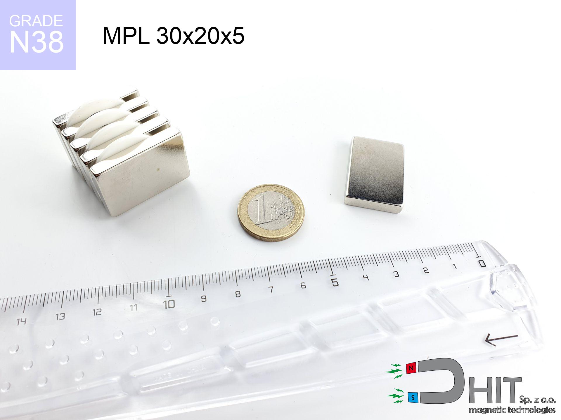
MPL 30x20x5 / N38 - lamellar magnet
lamellar magnet
Catalog no 020143
GTIN/EAN: 5906301811497
length
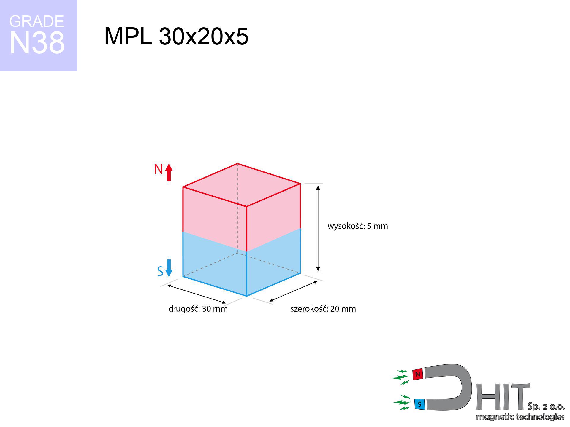
30 mm [±0,1 mm]
Width
20 mm [±0,1 mm]
Height
5 mm [±0,1 mm]
Weight
22.5 g
Magnetization Direction
↑ axial
Load capacity
8.86 kg / 86.90 N
Magnetic Induction
220.03 mT / 2200 Gs
Coating
[NiCuNi] Nickel
9.10 ZŁ with VAT / pcs + price for transport
7.40 ZŁ net + 23% VAT / pcs
bulk discounts:
Need more?Engineering report for this magnet
Full PDF analysis: pull and shear force, effect of distance, temperature and plate thickness, safety distances and the demagnetization curve.
Call us
+48 22 499 98 98
if you prefer send us a note by means of
form
through our site.
Lifting power and form of a magnet can be estimated on our
online calculation tool.
Orders submitted before 14:00 will be dispatched today!
Physical properties - MPL 30x20x5 / N38 - lamellar magnet
Specification / characteristics - MPL 30x20x5 / N38 - lamellar magnet
| properties | values |
|---|---|
| Cat. no. | 020143 |
| GTIN/EAN | 5906301811497 |
| Production/Distribution | Dhit sp. z o.o. |
| Country of origin | Poland / China / Germany |
| Customs code | 85059029 |
| length | 30 mm [±0,1 mm] |
| Width | 20 mm [±0,1 mm] |
| Height | 5 mm [±0,1 mm] |
| Weight | 22.5 g |
| Magnetization Direction | ↑ axial |
| Load capacity ~ ? | 8.86 kg / 86.90 N |
| Magnetic Induction ~ ? | 220.03 mT / 2200 Gs |
| Coating | [NiCuNi] Nickel |
| Manufacturing Tolerance | ±0.1 mm |
Magnetic properties of material N38
| properties | values | units |
|---|---|---|
| remenance Br [min. - max.] ? | 12.2-12.6 | kGs |
| remenance Br [min. - max.] ? | 1220-1260 | mT |
| coercivity bHc ? | 10.8-11.5 | kOe |
| coercivity bHc ? | 860-915 | kA/m |
| actual internal force iHc | ≥ 12 | kOe |
| actual internal force iHc | ≥ 955 | kA/m |
| energy density [min. - max.] ? | 36-38 | BH max MGOe |
| energy density [min. - max.] ? | 287-303 | BH max KJ/m |
| max. temperature ? | ≤ 80 | °C |
Physical properties of sintered neodymium magnets Nd2Fe14B at 20°C
| properties | values | units |
|---|---|---|
| Vickers hardness | ≥550 | Hv |
| Density | ≥7.4 | g/cm3 |
| Curie Temperature TC | 312 - 380 | °C |
| Curie Temperature TF | 593 - 716 | °F |
| Specific resistance | 150 | μΩ⋅cm |
| Bending strength | 250 | MPa |
| Compressive strength | 1000~1100 | MPa |
| Thermal expansion parallel (∥) to orientation (M) | (3-4) x 10-6 | °C-1 |
| Thermal expansion perpendicular (⊥) to orientation (M) | -(1-3) x 10-6 | °C-1 |
| Young's modulus | 1.7 x 10⁴ | kg/mm² |
Physical modeling of the assembly - data
Presented information represent the outcome of a physical calculation. Values are based on algorithms for the material Nd2Fe14B. Real-world parameters might slightly deviate from the simulation results. Treat these calculations as a preliminary roadmap for designers.
Table 1: Static pull force (force vs distance) - characteristics
MPL 30x20x5 / N38
| Distance (mm) | Induction (Gauss) / mT | Pull Force (kg/lbs/g/N) | Risk Status |
|---|---|---|---|
| 0 mm |
2200 Gs
220.0 mT
|
8.86 kg / 19.53 pounds
8860.0 g / 86.9 N
|
medium risk |
| 1 mm |
2092 Gs
209.2 mT
|
8.01 kg / 17.67 pounds
8013.9 g / 78.6 N
|
medium risk |
| 2 mm |
1961 Gs
196.1 mT
|
7.04 kg / 15.53 pounds
7042.1 g / 69.1 N
|
medium risk |
| 3 mm |
1817 Gs
181.7 mT
|
6.04 kg / 13.32 pounds
6041.8 g / 59.3 N
|
medium risk |
| 5 mm |
1516 Gs
151.6 mT
|
4.21 kg / 9.28 pounds
4209.6 g / 41.3 N
|
medium risk |
| 10 mm |
892 Gs
89.2 mT
|
1.46 kg / 3.21 pounds
1456.2 g / 14.3 N
|
weak grip |
| 15 mm |
519 Gs
51.9 mT
|
0.49 kg / 1.09 pounds
492.4 g / 4.8 N
|
weak grip |
| 20 mm |
313 Gs
31.3 mT
|
0.18 kg / 0.40 pounds
179.8 g / 1.8 N
|
weak grip |
| 30 mm |
132 Gs
13.2 mT
|
0.03 kg / 0.07 pounds
31.9 g / 0.3 N
|
weak grip |
| 50 mm |
37 Gs
3.7 mT
|
0.00 kg / 0.01 pounds
2.5 g / 0.0 N
|
weak grip |
Table 2: Shear load (vertical surface)
MPL 30x20x5 / N38
| Distance (mm) | Friction coefficient | Pull Force (kg/lbs/g/N) |
|---|---|---|
| 0 mm | Stal (~0.2) |
1.77 kg / 3.91 pounds
1772.0 g / 17.4 N
|
| 1 mm | Stal (~0.2) |
1.60 kg / 3.53 pounds
1602.0 g / 15.7 N
|
| 2 mm | Stal (~0.2) |
1.41 kg / 3.10 pounds
1408.0 g / 13.8 N
|
| 3 mm | Stal (~0.2) |
1.21 kg / 2.66 pounds
1208.0 g / 11.9 N
|
| 5 mm | Stal (~0.2) |
0.84 kg / 1.86 pounds
842.0 g / 8.3 N
|
| 10 mm | Stal (~0.2) |
0.29 kg / 0.64 pounds
292.0 g / 2.9 N
|
| 15 mm | Stal (~0.2) |
0.10 kg / 0.22 pounds
98.0 g / 1.0 N
|
| 20 mm | Stal (~0.2) |
0.04 kg / 0.08 pounds
36.0 g / 0.4 N
|
| 30 mm | Stal (~0.2) |
0.01 kg / 0.01 pounds
6.0 g / 0.1 N
|
| 50 mm | Stal (~0.2) |
0.00 kg / 0.00 pounds
0.0 g / 0.0 N
|
Table 3: Vertical assembly (sliding) - vertical pull
MPL 30x20x5 / N38
| Surface type | Friction coefficient / % Mocy | Max load (kg/lbs/g/N) |
|---|---|---|
| Raw steel |
µ = 0.3
30% Nominalnej Siły
|
2.66 kg / 5.86 pounds
2658.0 g / 26.1 N
|
| Painted steel (standard) |
µ = 0.2
20% Nominalnej Siły
|
1.77 kg / 3.91 pounds
1772.0 g / 17.4 N
|
| Oily/slippery steel |
µ = 0.1
10% Nominalnej Siły
|
0.89 kg / 1.95 pounds
886.0 g / 8.7 N
|
| Magnet with anti-slip rubber |
µ = 0.5
50% Nominalnej Siły
|
4.43 kg / 9.77 pounds
4430.0 g / 43.5 N
|
Table 4: Material efficiency (saturation) - sheet metal selection
MPL 30x20x5 / N38
| Steel thickness (mm) | % power | Real pull force (kg/lbs/g/N) |
|---|---|---|
| 0.5 mm |
|
0.89 kg / 1.95 pounds
886.0 g / 8.7 N
|
| 1 mm |
|
2.22 kg / 4.88 pounds
2215.0 g / 21.7 N
|
| 2 mm |
|
4.43 kg / 9.77 pounds
4430.0 g / 43.5 N
|
| 3 mm |
|
6.65 kg / 14.65 pounds
6645.0 g / 65.2 N
|
| 5 mm |
|
8.86 kg / 19.53 pounds
8860.0 g / 86.9 N
|
| 10 mm |
|
8.86 kg / 19.53 pounds
8860.0 g / 86.9 N
|
| 11 mm |
|
8.86 kg / 19.53 pounds
8860.0 g / 86.9 N
|
| 12 mm |
|
8.86 kg / 19.53 pounds
8860.0 g / 86.9 N
|
Table 5: Thermal stability (material behavior) - thermal limit
MPL 30x20x5 / N38
| Ambient temp. (°C) | Power loss | Remaining pull (kg/lbs/g/N) | Status |
|---|---|---|---|
| 20 °C | 0.0% |
8.86 kg / 19.53 pounds
8860.0 g / 86.9 N
|
OK |
| 40 °C | -2.2% |
8.67 kg / 19.10 pounds
8665.1 g / 85.0 N
|
OK |
| 60 °C | -4.4% |
8.47 kg / 18.67 pounds
8470.2 g / 83.1 N
|
|
| 80 °C | -6.6% |
8.28 kg / 18.24 pounds
8275.2 g / 81.2 N
|
|
| 100 °C | -28.8% |
6.31 kg / 13.91 pounds
6308.3 g / 61.9 N
|
Table 6: Magnet-Magnet interaction (attraction) - field collision
MPL 30x20x5 / N38
| Gap (mm) | Attraction (kg/lbs) (N-S) | Lateral Force (kg/lbs/g/N) | Repulsion (kg/lbs) (N-N) |
|---|---|---|---|
| 0 mm |
17.90 kg / 39.47 pounds
3 715 Gs
|
2.69 kg / 5.92 pounds
2685 g / 26.3 N
|
N/A |
| 1 mm |
17.10 kg / 37.69 pounds
4 300 Gs
|
2.56 kg / 5.65 pounds
2565 g / 25.2 N
|
15.39 kg / 33.92 pounds
~0 Gs
|
| 2 mm |
16.19 kg / 35.70 pounds
4 184 Gs
|
2.43 kg / 5.35 pounds
2429 g / 23.8 N
|
14.57 kg / 32.13 pounds
~0 Gs
|
| 3 mm |
15.23 kg / 33.57 pounds
4 058 Gs
|
2.28 kg / 5.04 pounds
2284 g / 22.4 N
|
13.71 kg / 30.22 pounds
~0 Gs
|
| 5 mm |
13.22 kg / 29.14 pounds
3 780 Gs
|
1.98 kg / 4.37 pounds
1982 g / 19.4 N
|
11.89 kg / 26.22 pounds
~0 Gs
|
| 10 mm |
8.51 kg / 18.75 pounds
3 033 Gs
|
1.28 kg / 2.81 pounds
1276 g / 12.5 N
|
7.66 kg / 16.88 pounds
~0 Gs
|
| 20 mm |
2.94 kg / 6.49 pounds
1 784 Gs
|
0.44 kg / 0.97 pounds
441 g / 4.3 N
|
2.65 kg / 5.84 pounds
~0 Gs
|
| 50 mm |
0.15 kg / 0.32 pounds
398 Gs
|
0.02 kg / 0.05 pounds
22 g / 0.2 N
|
0.13 kg / 0.29 pounds
~0 Gs
|
| 60 mm |
0.06 kg / 0.14 pounds
264 Gs
|
0.01 kg / 0.02 pounds
10 g / 0.1 N
|
0.06 kg / 0.13 pounds
~0 Gs
|
| 70 mm |
0.03 kg / 0.07 pounds
183 Gs
|
0.00 kg / 0.01 pounds
5 g / 0.0 N
|
0.03 kg / 0.06 pounds
~0 Gs
|
| 80 mm |
0.02 kg / 0.04 pounds
131 Gs
|
0.00 kg / 0.01 pounds
2 g / 0.0 N
|
0.01 kg / 0.03 pounds
~0 Gs
|
| 90 mm |
0.01 kg / 0.02 pounds
97 Gs
|
0.00 kg / 0.00 pounds
1 g / 0.0 N
|
0.00 kg / 0.00 pounds
~0 Gs
|
| 100 mm |
0.00 kg / 0.01 pounds
73 Gs
|
0.00 kg / 0.00 pounds
1 g / 0.0 N
|
0.00 kg / 0.00 pounds
~0 Gs
|
Table 7: Protective zones (implants) - precautionary measures
MPL 30x20x5 / N38
| Object / Device | Limit (Gauss) / mT | Safe distance |
|---|---|---|
| Pacemaker | 5 Gs (0.5 mT) | 10.5 cm |
| Hearing aid | 10 Gs (1.0 mT) | 8.5 cm |
| Mechanical watch | 20 Gs (2.0 mT) | 6.5 cm |
| Mobile device | 40 Gs (4.0 mT) | 5.0 cm |
| Car key | 50 Gs (5.0 mT) | 4.5 cm |
| Payment card | 400 Gs (40.0 mT) | 2.0 cm |
| HDD hard drive | 600 Gs (60.0 mT) | 1.5 cm |
Table 8: Impact energy (cracking risk) - warning
MPL 30x20x5 / N38
| Start from (mm) | Speed (km/h) | Energy (J) | Predicted outcome |
|---|---|---|---|
| 10 mm |
21.97 km/h
(6.10 m/s)
|
0.42 J | |
| 30 mm |
34.74 km/h
(9.65 m/s)
|
1.05 J | |
| 50 mm |
44.76 km/h
(12.43 m/s)
|
1.74 J | |
| 100 mm |
63.29 km/h
(17.58 m/s)
|
3.48 J |
Table 9: Coating parameters (durability)
MPL 30x20x5 / N38
| Technical parameter | Value / Description |
|---|---|
| Coating type | [NiCuNi] Nickel |
| Layer structure | Nickel - Copper - Nickel |
| Layer thickness | 10-20 µm |
| Salt spray test (SST) ? | 24 h |
| Recommended environment | Indoors only (dry) |
Table 10: Construction data (Pc)
MPL 30x20x5 / N38
| Parameter | Value | SI Unit / Description |
|---|---|---|
| Magnetic Flux | 14 969 Mx | 149.7 µWb |
| Pc Coefficient | 0.26 | Low (Flat) |
Table 11: Underwater work (magnet fishing)
MPL 30x20x5 / N38
| Environment | Effective steel pull | Effect |
|---|---|---|
| Air (land) | 8.86 kg | Standard |
| Water (riverbed) |
10.14 kg
(+1.28 kg buoyancy gain)
|
+14.5% |
1. Shear force
*Note: On a vertical surface, the magnet retains just approx. 20-30% of its max power.
2. Efficiency vs thickness
*Thin steel (e.g. 0.5mm PC case) severely weakens the holding force.
3. Power loss vs temp
*For N38 grade, the safety limit is 80°C.
4. Demagnetization curve and operating point (B-H)
chart generated for the permeance coefficient Pc (Permeance Coefficient) = 0.26
The chart above illustrates the magnetic characteristics of the material within the second quadrant of the hysteresis loop. The solid red line represents the demagnetization curve (material potential), while the dashed blue line is the load line based on the magnet's geometry. The Pc (Permeance Coefficient), also known as the load line slope, is a dimensionless value that describes the relationship between the magnet's shape and its magnetic stability. The intersection of these two lines (the black dot) is the operating point — it determines the actual magnetic flux density generated by the magnet in this specific configuration. A higher Pc value means the magnet is more 'slender' (tall relative to its area), resulting in a higher operating point and better resistance to irreversible demagnetization caused by external fields or temperature. A value of 0.42 is relatively low (typical for flat magnets), meaning the operating point is closer to the 'knee' of the curve — caution is advised when operating at temperatures near the maximum limit to avoid strength loss.
Elemental analysis
| iron (Fe) | 64% – 68% |
| neodymium (Nd) | 29% – 32% |
| boron (B) | 1.1% – 1.2% |
| dysprosium (Dy) | 0.5% – 2.0% |
| coating (Ni-Cu-Ni) | < 0.05% |
Sustainability
| recyclability (EoL) | 100% |
| recycled raw materials | ~10% (pre-cons) |
| carbon footprint | low / zredukowany |
| waste code (EWC) | 16 02 16 |
Other deals

![HH 25x7.7 [M5] / N38 - through hole magnetic holder](https://cdn3.dhit.pl/graphics/products/hh-25x7.7-m5-pov.jpg "HH 25x7.7 [M5] / N38 - through hole magnetic holder")


Pros as well as cons of neodymium magnets.
Pros
- They virtually do not lose power, because even after ten years the decline in efficiency is only ~1% (according to literature),
- Magnets effectively defend themselves against loss of magnetization caused by ambient magnetic noise,
- In other words, due to the smooth surface of silver, the element becomes visually attractive,
- Neodymium magnets ensure maximum magnetic induction on a contact point, which ensures high operational effectiveness,
- Due to their durability and thermal resistance, neodymium magnets are capable of operate (depending on the form) even at high temperatures reaching 230°C or more...
- Thanks to versatility in shaping and the capacity to adapt to specific needs,
- Versatile presence in electronics industry – they are used in hard drives, electric motors, precision medical tools, and other advanced devices.
- Thanks to concentrated force, small magnets offer high operating force, occupying minimum space,
Cons
- At strong impacts they can crack, therefore we advise placing them in steel cases. A metal housing provides additional protection against damage and increases the magnet's durability.
- We warn that neodymium magnets can lose their strength at high temperatures. To prevent this, we suggest our specialized [AH] magnets, which work effectively even at 230°C.
- Magnets exposed to a humid environment can corrode. Therefore when using outdoors, we advise using waterproof magnets made of rubber, plastic or other material protecting against moisture
- Limited possibility of producing threads in the magnet and complex shapes - recommended is casing - magnetic holder.
- Potential hazard resulting from small fragments of magnets can be dangerous, if swallowed, which becomes key in the aspect of protecting the youngest. It is also worth noting that tiny parts of these products are able to be problematic in diagnostics medical when they are in the body.
- With large orders the cost of neodymium magnets can be a barrier,
Pull force analysis
Magnetic strength at its maximum – what it depends on?
- with the use of a yoke made of special test steel, guaranteeing maximum field concentration
- whose transverse dimension is min. 10 mm
- with a surface cleaned and smooth
- under conditions of gap-free contact (surface-to-surface)
- for force acting at a right angle (pull-off, not shear)
- at conditions approx. 20°C
Magnet lifting force in use – key factors
- Gap (betwixt the magnet and the plate), since even a very small distance (e.g. 0.5 mm) leads to a drastic drop in force by up to 50% (this also applies to varnish, corrosion or debris).
- Angle of force application – maximum parameter is obtained only during pulling at a 90° angle. The shear force of the magnet along the surface is standardly several times smaller (approx. 1/5 of the lifting capacity).
- Substrate thickness – for full efficiency, the steel must be sufficiently thick. Paper-thin metal limits the lifting capacity (the magnet "punches through" it).
- Steel type – mild steel attracts best. Alloy admixtures reduce magnetic properties and lifting capacity.
- Plate texture – smooth surfaces ensure maximum contact, which increases field saturation. Uneven metal reduce efficiency.
- Thermal environment – temperature increase results in weakening of force. It is worth remembering the maximum operating temperature for a given model.
Lifting capacity was measured using a polished steel plate of optimal thickness (min. 20 mm), under perpendicular detachment force, whereas under attempts to slide the magnet the holding force is lower. Additionally, even a minimal clearance between the magnet’s surface and the plate decreases the lifting capacity.
H&S for magnets
ICD Warning
Individuals with a pacemaker must maintain an safe separation from magnets. The magnetic field can disrupt the functioning of the life-saving device.
GPS Danger
GPS units and mobile phones are extremely susceptible to magnetic fields. Close proximity with a strong magnet can ruin the internal compass in your phone.
Keep away from computers
Intense magnetic fields can corrupt files on credit cards, HDDs, and other magnetic media. Stay away of min. 10 cm.
Handling guide
Use magnets consciously. Their immense force can shock even experienced users. Plan your moves and respect their power.
Crushing force
Danger of trauma: The pulling power is so great that it can result in hematomas, pinching, and even bone fractures. Use thick gloves.
Eye protection
Watch out for shards. Magnets can fracture upon uncontrolled impact, ejecting shards into the air. We recommend safety glasses.
Dust explosion hazard
Mechanical processing of neodymium magnets carries a risk of fire risk. Neodymium dust oxidizes rapidly with oxygen and is hard to extinguish.
Adults only
Product intended for adults. Small elements pose a choking risk, causing severe trauma. Store out of reach of children and animals.
Allergic reactions
It is widely known that the nickel plating (standard magnet coating) is a common allergen. If your skin reacts to metals, avoid direct skin contact or opt for versions in plastic housing.
Maximum temperature
Monitor thermal conditions. Exposing the magnet to high heat will ruin its magnetic structure and strength.
Tabela kosztu i czasu dostawy
Płatność przed wysyłką:

GLS kurier
Przesyłka będzie u Ciebie za 2-3 dni
14.99 ZŁ

InPost Paczkomaty 24/7
Przesyłka będzie u Ciebie za 1-2 dni
12.30 ZŁ
Płatność przy odbiorze (pobranie):
GLS kurier
Przesyłka będzie u Ciebie za 1-2 dni
23.00 ZŁ
Rate the product
Your rating