
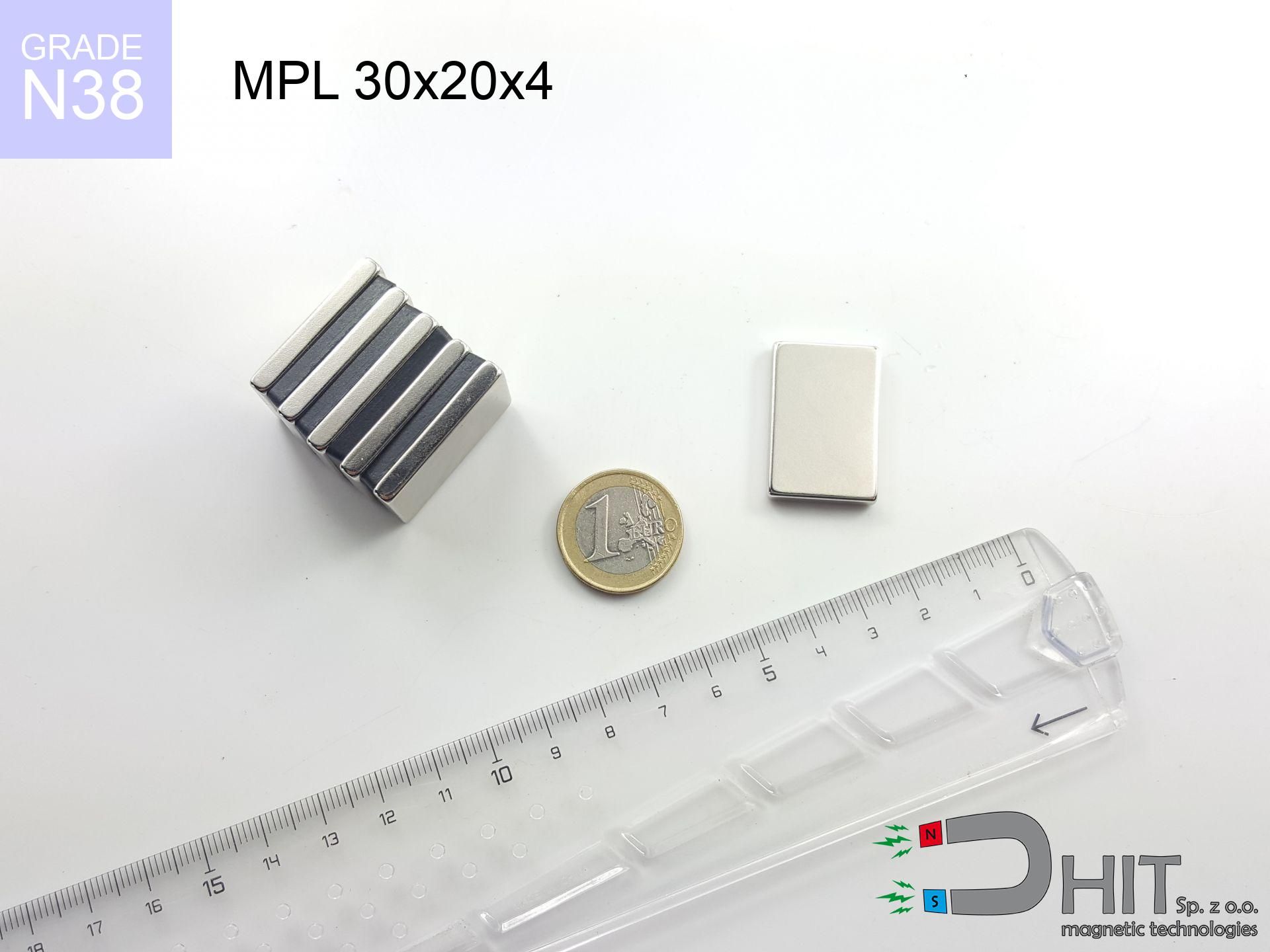
MPL 30x20x4 / N38 - lamellar magnet
lamellar magnet
Catalog no 020286
GTIN/EAN: 5906301811848
length
30 mm [±0,1 mm]
Width
20 mm [±0,1 mm]
Height
4 mm [±0,1 mm]
Weight
18 g
Magnetization Direction
↑ axial
Load capacity
6.30 kg / 61.84 N
Magnetic Induction
180.57 mT / 1806 Gs
Coating
[NiCuNi] Nickel
10.23 ZŁ with VAT / pcs + price for transport
8.32 ZŁ net + 23% VAT / pcs
bulk discounts:
Need more?
Contact us by phone
+48 888 99 98 98
if you prefer let us know using
inquiry form
the contact section.
Force along with form of a magnet can be tested using our
magnetic mass calculator.
Same-day shipping for orders placed before 14:00.
Detailed specification - MPL 30x20x4 / N38 - lamellar magnet
Specification / characteristics - MPL 30x20x4 / N38 - lamellar magnet
| properties | values |
|---|---|
| Cat. no. | 020286 |
| GTIN/EAN | 5906301811848 |
| Production/Distribution | Dhit sp. z o.o. |
| Country of origin | Poland / China / Germany |
| Customs code | 85059029 |
| length | 30 mm [±0,1 mm] |
| Width | 20 mm [±0,1 mm] |
| Height | 4 mm [±0,1 mm] |
| Weight | 18 g |
| Magnetization Direction | ↑ axial |
| Load capacity ~ ? | 6.30 kg / 61.84 N |
| Magnetic Induction ~ ? | 180.57 mT / 1806 Gs |
| Coating | [NiCuNi] Nickel |
| Manufacturing Tolerance | ±0.1 mm |
Magnetic properties of material N38
| properties | values | units |
|---|---|---|
| remenance Br [min. - max.] ? | 12.2-12.6 | kGs |
| remenance Br [min. - max.] ? | 1220-1260 | mT |
| coercivity bHc ? | 10.8-11.5 | kOe |
| coercivity bHc ? | 860-915 | kA/m |
| actual internal force iHc | ≥ 12 | kOe |
| actual internal force iHc | ≥ 955 | kA/m |
| energy density [min. - max.] ? | 36-38 | BH max MGOe |
| energy density [min. - max.] ? | 287-303 | BH max KJ/m |
| max. temperature ? | ≤ 80 | °C |
Physical properties of sintered neodymium magnets Nd2Fe14B at 20°C
| properties | values | units |
|---|---|---|
| Vickers hardness | ≥550 | Hv |
| Density | ≥7.4 | g/cm3 |
| Curie Temperature TC | 312 - 380 | °C |
| Curie Temperature TF | 593 - 716 | °F |
| Specific resistance | 150 | μΩ⋅cm |
| Bending strength | 250 | MPa |
| Compressive strength | 1000~1100 | MPa |
| Thermal expansion parallel (∥) to orientation (M) | (3-4) x 10-6 | °C-1 |
| Thermal expansion perpendicular (⊥) to orientation (M) | -(1-3) x 10-6 | °C-1 |
| Young's modulus | 1.7 x 10⁴ | kg/mm² |
Technical modeling of the assembly - report
These data represent the result of a physical analysis. Results are based on algorithms for the class Nd2Fe14B. Real-world parameters might slightly deviate from the simulation results. Treat these data as a supplementary guide during assembly planning.
Table 1: Static force (pull vs gap) - interaction chart
MPL 30x20x4 / N38
| Distance (mm) | Induction (Gauss) / mT | Pull Force (kg/lbs/g/N) | Risk Status |
|---|---|---|---|
| 0 mm |
1805 Gs
180.5 mT
|
6.30 kg / 13.89 pounds
6300.0 g / 61.8 N
|
medium risk |
| 1 mm |
1728 Gs
172.8 mT
|
5.77 kg / 12.72 pounds
5771.5 g / 56.6 N
|
medium risk |
| 2 mm |
1628 Gs
162.8 mT
|
5.13 kg / 11.30 pounds
5125.7 g / 50.3 N
|
medium risk |
| 3 mm |
1515 Gs
151.5 mT
|
4.43 kg / 9.78 pounds
4434.6 g / 43.5 N
|
medium risk |
| 5 mm |
1271 Gs
127.1 mT
|
3.12 kg / 6.89 pounds
3124.3 g / 30.6 N
|
medium risk |
| 10 mm |
751 Gs
75.1 mT
|
1.09 kg / 2.40 pounds
1088.7 g / 10.7 N
|
low risk |
| 15 mm |
435 Gs
43.5 mT
|
0.37 kg / 0.81 pounds
366.3 g / 3.6 N
|
low risk |
| 20 mm |
262 Gs
26.2 mT
|
0.13 kg / 0.29 pounds
132.6 g / 1.3 N
|
low risk |
| 30 mm |
110 Gs
11.0 mT
|
0.02 kg / 0.05 pounds
23.2 g / 0.2 N
|
low risk |
| 50 mm |
30 Gs
3.0 mT
|
0.00 kg / 0.00 pounds
1.8 g / 0.0 N
|
low risk |
Table 2: Slippage load (wall)
MPL 30x20x4 / N38
| Distance (mm) | Friction coefficient | Pull Force (kg/lbs/g/N) |
|---|---|---|
| 0 mm | Stal (~0.2) |
1.26 kg / 2.78 pounds
1260.0 g / 12.4 N
|
| 1 mm | Stal (~0.2) |
1.15 kg / 2.54 pounds
1154.0 g / 11.3 N
|
| 2 mm | Stal (~0.2) |
1.03 kg / 2.26 pounds
1026.0 g / 10.1 N
|
| 3 mm | Stal (~0.2) |
0.89 kg / 1.95 pounds
886.0 g / 8.7 N
|
| 5 mm | Stal (~0.2) |
0.62 kg / 1.38 pounds
624.0 g / 6.1 N
|
| 10 mm | Stal (~0.2) |
0.22 kg / 0.48 pounds
218.0 g / 2.1 N
|
| 15 mm | Stal (~0.2) |
0.07 kg / 0.16 pounds
74.0 g / 0.7 N
|
| 20 mm | Stal (~0.2) |
0.03 kg / 0.06 pounds
26.0 g / 0.3 N
|
| 30 mm | Stal (~0.2) |
0.00 kg / 0.01 pounds
4.0 g / 0.0 N
|
| 50 mm | Stal (~0.2) |
0.00 kg / 0.00 pounds
0.0 g / 0.0 N
|
Table 3: Wall mounting (sliding) - vertical pull
MPL 30x20x4 / N38
| Surface type | Friction coefficient / % Mocy | Max load (kg/lbs/g/N) |
|---|---|---|
| Raw steel |
µ = 0.3
30% Nominalnej Siły
|
1.89 kg / 4.17 pounds
1890.0 g / 18.5 N
|
| Painted steel (standard) |
µ = 0.2
20% Nominalnej Siły
|
1.26 kg / 2.78 pounds
1260.0 g / 12.4 N
|
| Oily/slippery steel |
µ = 0.1
10% Nominalnej Siły
|
0.63 kg / 1.39 pounds
630.0 g / 6.2 N
|
| Magnet with anti-slip rubber |
µ = 0.5
50% Nominalnej Siły
|
3.15 kg / 6.94 pounds
3150.0 g / 30.9 N
|
Table 4: Steel thickness (substrate influence) - power losses
MPL 30x20x4 / N38
| Steel thickness (mm) | % power | Real pull force (kg/lbs/g/N) |
|---|---|---|
| 0.5 mm |
|
0.63 kg / 1.39 pounds
630.0 g / 6.2 N
|
| 1 mm |
|
1.58 kg / 3.47 pounds
1575.0 g / 15.5 N
|
| 2 mm |
|
3.15 kg / 6.94 pounds
3150.0 g / 30.9 N
|
| 3 mm |
|
4.73 kg / 10.42 pounds
4725.0 g / 46.4 N
|
| 5 mm |
|
6.30 kg / 13.89 pounds
6300.0 g / 61.8 N
|
| 10 mm |
|
6.30 kg / 13.89 pounds
6300.0 g / 61.8 N
|
| 11 mm |
|
6.30 kg / 13.89 pounds
6300.0 g / 61.8 N
|
| 12 mm |
|
6.30 kg / 13.89 pounds
6300.0 g / 61.8 N
|
Table 5: Thermal resistance (stability) - power drop
MPL 30x20x4 / N38
| Ambient temp. (°C) | Power loss | Remaining pull (kg/lbs/g/N) | Status |
|---|---|---|---|
| 20 °C | 0.0% |
6.30 kg / 13.89 pounds
6300.0 g / 61.8 N
|
OK |
| 40 °C | -2.2% |
6.16 kg / 13.58 pounds
6161.4 g / 60.4 N
|
OK |
| 60 °C | -4.4% |
6.02 kg / 13.28 pounds
6022.8 g / 59.1 N
|
|
| 80 °C | -6.6% |
5.88 kg / 12.97 pounds
5884.2 g / 57.7 N
|
|
| 100 °C | -28.8% |
4.49 kg / 9.89 pounds
4485.6 g / 44.0 N
|
Table 6: Magnet-Magnet interaction (attraction) - field collision
MPL 30x20x4 / N38
| Gap (mm) | Attraction (kg/lbs) (N-S) | Shear Strength (kg/lbs/g/N) | Repulsion (kg/lbs) (N-N) |
|---|---|---|---|
| 0 mm |
12.06 kg / 26.58 pounds
3 198 Gs
|
1.81 kg / 3.99 pounds
1809 g / 17.7 N
|
N/A |
| 1 mm |
11.59 kg / 25.55 pounds
3 540 Gs
|
1.74 kg / 3.83 pounds
1739 g / 17.1 N
|
10.43 kg / 23.00 pounds
~0 Gs
|
| 2 mm |
11.05 kg / 24.35 pounds
3 456 Gs
|
1.66 kg / 3.65 pounds
1657 g / 16.3 N
|
9.94 kg / 21.92 pounds
~0 Gs
|
| 3 mm |
10.45 kg / 23.03 pounds
3 361 Gs
|
1.57 kg / 3.45 pounds
1567 g / 15.4 N
|
9.40 kg / 20.73 pounds
~0 Gs
|
| 5 mm |
9.15 kg / 20.18 pounds
3 146 Gs
|
1.37 kg / 3.03 pounds
1373 g / 13.5 N
|
8.24 kg / 18.16 pounds
~0 Gs
|
| 10 mm |
5.98 kg / 13.18 pounds
2 543 Gs
|
0.90 kg / 1.98 pounds
897 g / 8.8 N
|
5.38 kg / 11.86 pounds
~0 Gs
|
| 20 mm |
2.08 kg / 4.59 pounds
1 501 Gs
|
0.31 kg / 0.69 pounds
313 g / 3.1 N
|
1.88 kg / 4.13 pounds
~0 Gs
|
| 50 mm |
0.10 kg / 0.22 pounds
331 Gs
|
0.02 kg / 0.03 pounds
15 g / 0.1 N
|
0.09 kg / 0.20 pounds
~0 Gs
|
| 60 mm |
0.04 kg / 0.10 pounds
219 Gs
|
0.01 kg / 0.01 pounds
7 g / 0.1 N
|
0.04 kg / 0.09 pounds
~0 Gs
|
| 70 mm |
0.02 kg / 0.05 pounds
151 Gs
|
0.00 kg / 0.01 pounds
3 g / 0.0 N
|
0.02 kg / 0.04 pounds
~0 Gs
|
| 80 mm |
0.01 kg / 0.02 pounds
108 Gs
|
0.00 kg / 0.00 pounds
2 g / 0.0 N
|
0.01 kg / 0.02 pounds
~0 Gs
|
| 90 mm |
0.01 kg / 0.01 pounds
80 Gs
|
0.00 kg / 0.00 pounds
1 g / 0.0 N
|
0.00 kg / 0.00 pounds
~0 Gs
|
| 100 mm |
0.00 kg / 0.01 pounds
60 Gs
|
0.00 kg / 0.00 pounds
1 g / 0.0 N
|
0.00 kg / 0.00 pounds
~0 Gs
|
Table 7: Hazards (electronics) - precautionary measures
MPL 30x20x4 / N38
| Object / Device | Limit (Gauss) / mT | Safe distance |
|---|---|---|
| Pacemaker | 5 Gs (0.5 mT) | 10.0 cm |
| Hearing aid | 10 Gs (1.0 mT) | 7.5 cm |
| Mechanical watch | 20 Gs (2.0 mT) | 6.0 cm |
| Mobile device | 40 Gs (4.0 mT) | 4.5 cm |
| Remote | 50 Gs (5.0 mT) | 4.5 cm |
| Payment card | 400 Gs (40.0 mT) | 2.0 cm |
| HDD hard drive | 600 Gs (60.0 mT) | 1.5 cm |
Table 8: Impact energy (cracking risk) - collision effects
MPL 30x20x4 / N38
| Start from (mm) | Speed (km/h) | Energy (J) | Predicted outcome |
|---|---|---|---|
| 10 mm |
20.81 km/h
(5.78 m/s)
|
0.30 J | |
| 30 mm |
32.75 km/h
(9.10 m/s)
|
0.75 J | |
| 50 mm |
42.20 km/h
(11.72 m/s)
|
1.24 J | |
| 100 mm |
59.66 km/h
(16.57 m/s)
|
2.47 J |
Table 9: Surface protection spec
MPL 30x20x4 / N38
| Technical parameter | Value / Description |
|---|---|
| Coating type | [NiCuNi] Nickel |
| Layer structure | Nickel - Copper - Nickel |
| Layer thickness | 10-20 µm |
| Salt spray test (SST) ? | 24 h |
| Recommended environment | Indoors only (dry) |
Table 10: Electrical data (Pc)
MPL 30x20x4 / N38
| Parameter | Value | SI Unit / Description |
|---|---|---|
| Magnetic Flux | 12 775 Mx | 127.8 µWb |
| Pc Coefficient | 0.22 | Low (Flat) |
Table 11: Physics of underwater searching
MPL 30x20x4 / N38
| Environment | Effective steel pull | Effect |
|---|---|---|
| Air (land) | 6.30 kg | Standard |
| Water (riverbed) |
7.21 kg
(+0.91 kg buoyancy gain)
|
+14.5% |
1. Shear force
*Warning: On a vertical wall, the magnet holds merely a fraction of its max power.
2. Steel thickness impact
*Thin metal sheet (e.g. 0.5mm PC case) severely reduces the holding force.
3. Heat tolerance
*For N38 material, the max working temp is 80°C.
4. Demagnetization curve and operating point (B-H)
chart generated for the permeance coefficient Pc (Permeance Coefficient) = 0.22
This simulation demonstrates the magnetic stability of the selected magnet under specific geometric conditions. The solid red line represents the demagnetization curve (material potential), while the dashed blue line is the load line based on the magnet's geometry. The Pc (Permeance Coefficient), also known as the load line slope, is a dimensionless value that describes the relationship between the magnet's shape and its magnetic stability. The intersection of these two lines (the black dot) is the operating point — it determines the actual magnetic flux density generated by the magnet in this specific configuration. A higher Pc value means the magnet is more 'slender' (tall relative to its area), resulting in a higher operating point and better resistance to irreversible demagnetization caused by external fields or temperature. A value of 0.42 is relatively low (typical for flat magnets), meaning the operating point is closer to the 'knee' of the curve — caution is advised when operating at temperatures near the maximum limit to avoid strength loss.
Elemental analysis
| iron (Fe) | 64% – 68% |
| neodymium (Nd) | 29% – 32% |
| boron (B) | 1.1% – 1.2% |
| dysprosium (Dy) | 0.5% – 2.0% |
| coating (Ni-Cu-Ni) | < 0.05% |
Sustainability
| recyclability (EoL) | 100% |
| recycled raw materials | ~10% (pre-cons) |
| carbon footprint | low / zredukowany |
| waste code (EWC) | 16 02 16 |
See more products


![BM 510x180x70 [4x M8] - magnetic beam](https://cdn3.dhit.pl/graphics/products/bm-510x180x70-4x-m8-cem.jpg "BM 510x180x70 [4x M8] - magnetic beam")
![UMP 107x40 [M8+M10] GW F 400 kg / N38 - search holder](https://cdn3.dhit.pl/graphics/products/ump107x40-m8+m10-gw-f-400-kg-mup.jpg "UMP 107x40 [M8+M10] GW F 400 kg / N38 - search holder")
Pros as well as cons of Nd2Fe14B magnets.
Pros
- Their strength is maintained, and after around 10 years it decreases only by ~1% (theoretically),
- Magnets perfectly defend themselves against loss of magnetization caused by foreign field sources,
- The use of an refined coating of noble metals (nickel, gold, silver) causes the element to be more visually attractive,
- They feature high magnetic induction at the operating surface, making them more effective,
- Thanks to resistance to high temperature, they are able to function (depending on the shape) even at temperatures up to 230°C and higher...
- Thanks to freedom in shaping and the capacity to modify to individual projects,
- Huge importance in advanced technology sectors – they are used in HDD drives, drive modules, medical equipment, also industrial machines.
- Thanks to concentrated force, small magnets offer high operating force, occupying minimum space,
Limitations
- They are prone to damage upon heavy impacts. To avoid cracks, it is worth protecting magnets using a steel holder. Such protection not only shields the magnet but also increases its resistance to damage
- Neodymium magnets lose their strength under the influence of heating. As soon as 80°C is exceeded, many of them start losing their force. Therefore, we recommend our special magnets marked [AH], which maintain durability even at temperatures up to 230°C
- Due to the susceptibility of magnets to corrosion in a humid environment, we advise using waterproof magnets made of rubber, plastic or other material immune to moisture, when using outdoors
- Due to limitations in producing nuts and complicated forms in magnets, we recommend using casing - magnetic mount.
- Potential hazard resulting from small fragments of magnets are risky, when accidentally swallowed, which gains importance in the aspect of protecting the youngest. Furthermore, tiny parts of these devices are able to be problematic in diagnostics medical when they are in the body.
- Due to neodymium price, their price is relatively high,
Holding force characteristics
Best holding force of the magnet in ideal parameters – what affects it?
- using a base made of low-carbon steel, acting as a circuit closing element
- possessing a massiveness of min. 10 mm to avoid saturation
- with a plane perfectly flat
- with zero gap (without impurities)
- under perpendicular force vector (90-degree angle)
- at conditions approx. 20°C
What influences lifting capacity in practice
- Gap (betwixt the magnet and the metal), as even a tiny clearance (e.g. 0.5 mm) leads to a decrease in lifting capacity by up to 50% (this also applies to paint, rust or dirt).
- Force direction – declared lifting capacity refers to pulling vertically. When attempting to slide, the magnet holds much less (often approx. 20-30% of nominal force).
- Substrate thickness – for full efficiency, the steel must be adequately massive. Thin sheet restricts the lifting capacity (the magnet "punches through" it).
- Chemical composition of the base – low-carbon steel gives the best results. Alloy admixtures lower magnetic permeability and lifting capacity.
- Smoothness – ideal contact is possible only on polished steel. Rough texture create air cushions, reducing force.
- Temperature – heating the magnet results in weakening of force. Check the thermal limit for a given model.
Holding force was tested on a smooth steel plate of 20 mm thickness, when a perpendicular force was applied, in contrast under parallel forces the holding force is lower. Moreover, even a small distance between the magnet’s surface and the plate reduces the holding force.
Safe handling of NdFeB magnets
Dust explosion hazard
Dust produced during machining of magnets is flammable. Do not drill into magnets without proper cooling and knowledge.
Precision electronics
GPS units and smartphones are extremely sensitive to magnetic fields. Direct contact with a strong magnet can ruin the internal compass in your phone.
Cards and drives
Avoid bringing magnets close to a purse, laptop, or TV. The magnetism can irreversibly ruin these devices and erase data from cards.
Danger to pacemakers
Patients with a ICD have to maintain an safe separation from magnets. The magnetism can disrupt the functioning of the implant.
Swallowing risk
Absolutely store magnets away from children. Ingestion danger is high, and the effects of magnets connecting inside the body are life-threatening.
Permanent damage
Do not overheat. Neodymium magnets are susceptible to temperature. If you need operation above 80°C, ask us about special high-temperature series (H, SH, UH).
Risk of cracking
Despite metallic appearance, neodymium is delicate and not impact-resistant. Do not hit, as the magnet may crumble into hazardous fragments.
Safe operation
Handle magnets with awareness. Their powerful strength can surprise even professionals. Plan your moves and do not underestimate their force.
Crushing risk
Protect your hands. Two powerful magnets will join immediately with a force of several hundred kilograms, destroying everything in their path. Exercise extreme caution!
Allergy Warning
Medical facts indicate that the nickel plating (the usual finish) is a potent allergen. If you have an allergy, avoid touching magnets with bare hands or choose coated magnets.
Tabela kosztu i czasu dostawy
Płatność przed wysyłką:

GLS kurier
Przesyłka będzie u Ciebie za 2-3 dni
14.99 ZŁ

InPost Paczkomaty 24/7
Przesyłka będzie u Ciebie za 1-2 dni
12.30 ZŁ
Płatność przy odbiorze (pobranie):
GLS kurier
Przesyłka będzie u Ciebie za 1-2 dni
23.00 ZŁ
Rate the product
Your rating