
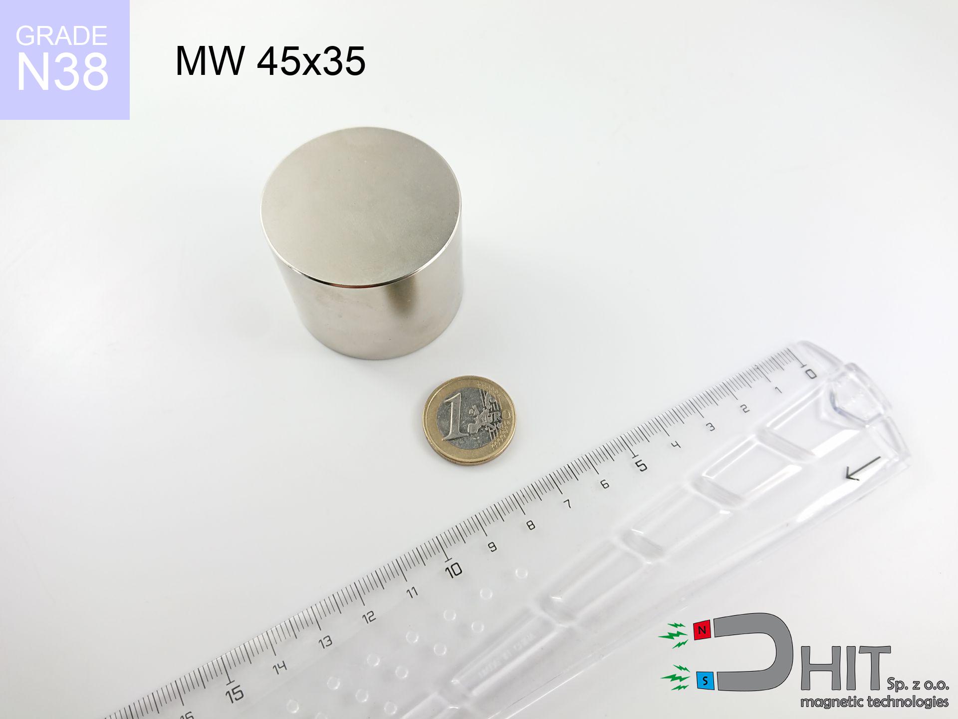
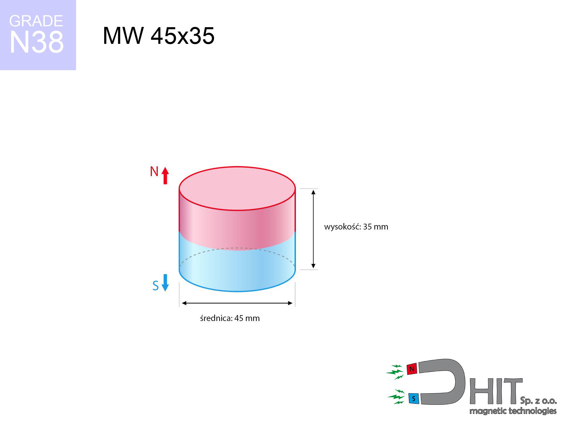
MW 45x35 / N38 - cylindrical magnet
cylindrical magnet
Catalog no 010074
GTIN/EAN: 5906301810735
Diameter Ø
45 mm [±0,1 mm]
Height
35 mm [±0,1 mm]
Weight
417.49 g
Magnetization Direction
↑ axial
Load capacity
68.98 kg / 676.73 N
Magnetic Induction
521.39 mT / 5214 Gs
Coating
[NiCuNi] Nickel
180.10 ZŁ with VAT / pcs + price for transport
146.42 ZŁ net + 23% VAT / pcs
bulk discounts:
Need more?
Give us a call
+48 22 499 98 98
if you prefer get in touch by means of
contact form
our website.
Parameters along with appearance of neodymium magnets can be calculated with our
our magnetic calculator.
Order by 14:00 and we’ll ship today!
Product card - MW 45x35 / N38 - cylindrical magnet
Specification / characteristics - MW 45x35 / N38 - cylindrical magnet
| properties | values |
|---|---|
| Cat. no. | 010074 |
| GTIN/EAN | 5906301810735 |
| Production/Distribution | Dhit sp. z o.o. |
| Country of origin | Poland / China / Germany |
| Customs code | 85059029 |
| Diameter Ø | 45 mm [±0,1 mm] |
| Height | 35 mm [±0,1 mm] |
| Weight | 417.49 g |
| Magnetization Direction | ↑ axial |
| Load capacity ~ ? | 68.98 kg / 676.73 N |
| Magnetic Induction ~ ? | 521.39 mT / 5214 Gs |
| Coating | [NiCuNi] Nickel |
| Manufacturing Tolerance | ±0.1 mm |
Magnetic properties of material N38
| properties | values | units |
|---|---|---|
| remenance Br [min. - max.] ? | 12.2-12.6 | kGs |
| remenance Br [min. - max.] ? | 1220-1260 | mT |
| coercivity bHc ? | 10.8-11.5 | kOe |
| coercivity bHc ? | 860-915 | kA/m |
| actual internal force iHc | ≥ 12 | kOe |
| actual internal force iHc | ≥ 955 | kA/m |
| energy density [min. - max.] ? | 36-38 | BH max MGOe |
| energy density [min. - max.] ? | 287-303 | BH max KJ/m |
| max. temperature ? | ≤ 80 | °C |
Physical properties of sintered neodymium magnets Nd2Fe14B at 20°C
| properties | values | units |
|---|---|---|
| Vickers hardness | ≥550 | Hv |
| Density | ≥7.4 | g/cm3 |
| Curie Temperature TC | 312 - 380 | °C |
| Curie Temperature TF | 593 - 716 | °F |
| Specific resistance | 150 | μΩ⋅cm |
| Bending strength | 250 | MPa |
| Compressive strength | 1000~1100 | MPa |
| Thermal expansion parallel (∥) to orientation (M) | (3-4) x 10-6 | °C-1 |
| Thermal expansion perpendicular (⊥) to orientation (M) | -(1-3) x 10-6 | °C-1 |
| Young's modulus | 1.7 x 10⁴ | kg/mm² |
Physical analysis of the magnet - data
These data represent the direct effect of a mathematical simulation. Results are based on models for the class Nd2Fe14B. Actual performance might slightly differ. Treat these data as a supplementary guide when designing systems.
Table 1: Static pull force (pull vs gap) - characteristics
MW 45x35 / N38
| Distance (mm) | Induction (Gauss) / mT | Pull Force (kg/lbs/g/N) | Risk Status |
|---|---|---|---|
| 0 mm |
5213 Gs
521.3 mT
|
68.98 kg / 152.07 pounds
68980.0 g / 676.7 N
|
crushing |
| 1 mm |
4982 Gs
498.2 mT
|
63.01 kg / 138.91 pounds
63010.2 g / 618.1 N
|
crushing |
| 2 mm |
4748 Gs
474.8 mT
|
57.23 kg / 126.18 pounds
57234.3 g / 561.5 N
|
crushing |
| 3 mm |
4516 Gs
451.6 mT
|
51.76 kg / 114.10 pounds
51756.9 g / 507.7 N
|
crushing |
| 5 mm |
4059 Gs
405.9 mT
|
41.82 kg / 92.19 pounds
41816.3 g / 410.2 N
|
crushing |
| 10 mm |
3027 Gs
302.7 mT
|
23.26 kg / 51.29 pounds
23264.1 g / 228.2 N
|
crushing |
| 15 mm |
2215 Gs
221.5 mT
|
12.45 kg / 27.45 pounds
12451.1 g / 122.1 N
|
crushing |
| 20 mm |
1619 Gs
161.9 mT
|
6.66 kg / 14.67 pounds
6656.2 g / 65.3 N
|
warning |
| 30 mm |
899 Gs
89.9 mT
|
2.05 kg / 4.52 pounds
2051.1 g / 20.1 N
|
warning |
| 50 mm |
340 Gs
34.0 mT
|
0.29 kg / 0.65 pounds
292.8 g / 2.9 N
|
low risk |
Table 2: Slippage capacity (wall)
MW 45x35 / N38
| Distance (mm) | Friction coefficient | Pull Force (kg/lbs/g/N) |
|---|---|---|
| 0 mm | Stal (~0.2) |
13.80 kg / 30.41 pounds
13796.0 g / 135.3 N
|
| 1 mm | Stal (~0.2) |
12.60 kg / 27.78 pounds
12602.0 g / 123.6 N
|
| 2 mm | Stal (~0.2) |
11.45 kg / 25.23 pounds
11446.0 g / 112.3 N
|
| 3 mm | Stal (~0.2) |
10.35 kg / 22.82 pounds
10352.0 g / 101.6 N
|
| 5 mm | Stal (~0.2) |
8.36 kg / 18.44 pounds
8364.0 g / 82.1 N
|
| 10 mm | Stal (~0.2) |
4.65 kg / 10.26 pounds
4652.0 g / 45.6 N
|
| 15 mm | Stal (~0.2) |
2.49 kg / 5.49 pounds
2490.0 g / 24.4 N
|
| 20 mm | Stal (~0.2) |
1.33 kg / 2.94 pounds
1332.0 g / 13.1 N
|
| 30 mm | Stal (~0.2) |
0.41 kg / 0.90 pounds
410.0 g / 4.0 N
|
| 50 mm | Stal (~0.2) |
0.06 kg / 0.13 pounds
58.0 g / 0.6 N
|
Table 3: Wall mounting (shearing) - vertical pull
MW 45x35 / N38
| Surface type | Friction coefficient / % Mocy | Max load (kg/lbs/g/N) |
|---|---|---|
| Raw steel |
µ = 0.3
30% Nominalnej Siły
|
20.69 kg / 45.62 pounds
20694.0 g / 203.0 N
|
| Painted steel (standard) |
µ = 0.2
20% Nominalnej Siły
|
13.80 kg / 30.41 pounds
13796.0 g / 135.3 N
|
| Oily/slippery steel |
µ = 0.1
10% Nominalnej Siły
|
6.90 kg / 15.21 pounds
6898.0 g / 67.7 N
|
| Magnet with anti-slip rubber |
µ = 0.5
50% Nominalnej Siły
|
34.49 kg / 76.04 pounds
34490.0 g / 338.3 N
|
Table 4: Material efficiency (saturation) - sheet metal selection
MW 45x35 / N38
| Steel thickness (mm) | % power | Real pull force (kg/lbs/g/N) |
|---|---|---|
| 0.5 mm |
|
2.30 kg / 5.07 pounds
2299.3 g / 22.6 N
|
| 1 mm |
|
5.75 kg / 12.67 pounds
5748.3 g / 56.4 N
|
| 2 mm |
|
11.50 kg / 25.35 pounds
11496.7 g / 112.8 N
|
| 3 mm |
|
17.25 kg / 38.02 pounds
17245.0 g / 169.2 N
|
| 5 mm |
|
28.74 kg / 63.36 pounds
28741.7 g / 282.0 N
|
| 10 mm |
|
57.48 kg / 126.73 pounds
57483.3 g / 563.9 N
|
| 11 mm |
|
63.23 kg / 139.40 pounds
63231.7 g / 620.3 N
|
| 12 mm |
|
68.98 kg / 152.07 pounds
68980.0 g / 676.7 N
|
Table 5: Thermal stability (stability) - power drop
MW 45x35 / N38
| Ambient temp. (°C) | Power loss | Remaining pull (kg/lbs/g/N) | Status |
|---|---|---|---|
| 20 °C | 0.0% |
68.98 kg / 152.07 pounds
68980.0 g / 676.7 N
|
OK |
| 40 °C | -2.2% |
67.46 kg / 148.73 pounds
67462.4 g / 661.8 N
|
OK |
| 60 °C | -4.4% |
65.94 kg / 145.38 pounds
65944.9 g / 646.9 N
|
OK |
| 80 °C | -6.6% |
64.43 kg / 142.04 pounds
64427.3 g / 632.0 N
|
|
| 100 °C | -28.8% |
49.11 kg / 108.28 pounds
49113.8 g / 481.8 N
|
Table 6: Two magnets (attraction) - forces in the system
MW 45x35 / N38
| Gap (mm) | Attraction (kg/lbs) (N-S) | Lateral Force (kg/lbs/g/N) | Repulsion (kg/lbs) (N-N) |
|---|---|---|---|
| 0 mm |
266.45 kg / 587.43 pounds
5 900 Gs
|
39.97 kg / 88.11 pounds
39968 g / 392.1 N
|
N/A |
| 1 mm |
254.93 kg / 562.03 pounds
10 198 Gs
|
38.24 kg / 84.30 pounds
38240 g / 375.1 N
|
229.44 kg / 505.82 pounds
~0 Gs
|
| 2 mm |
243.39 kg / 536.59 pounds
9 965 Gs
|
36.51 kg / 80.49 pounds
36509 g / 358.2 N
|
219.05 kg / 482.93 pounds
~0 Gs
|
| 3 mm |
232.10 kg / 511.70 pounds
9 731 Gs
|
34.82 kg / 76.76 pounds
34816 g / 341.5 N
|
208.89 kg / 460.53 pounds
~0 Gs
|
| 5 mm |
210.35 kg / 463.75 pounds
9 264 Gs
|
31.55 kg / 69.56 pounds
31553 g / 309.5 N
|
189.32 kg / 417.37 pounds
~0 Gs
|
| 10 mm |
161.53 kg / 356.11 pounds
8 118 Gs
|
24.23 kg / 53.42 pounds
24229 g / 237.7 N
|
145.37 kg / 320.49 pounds
~0 Gs
|
| 20 mm |
89.86 kg / 198.12 pounds
6 055 Gs
|
13.48 kg / 29.72 pounds
13480 g / 132.2 N
|
80.88 kg / 178.30 pounds
~0 Gs
|
| 50 mm |
14.04 kg / 30.96 pounds
2 394 Gs
|
2.11 kg / 4.64 pounds
2107 g / 20.7 N
|
12.64 kg / 27.87 pounds
~0 Gs
|
| 60 mm |
7.92 kg / 17.47 pounds
1 798 Gs
|
1.19 kg / 2.62 pounds
1188 g / 11.7 N
|
7.13 kg / 15.72 pounds
~0 Gs
|
| 70 mm |
4.63 kg / 10.21 pounds
1 375 Gs
|
0.69 kg / 1.53 pounds
695 g / 6.8 N
|
4.17 kg / 9.19 pounds
~0 Gs
|
| 80 mm |
2.80 kg / 6.18 pounds
1 070 Gs
|
0.42 kg / 0.93 pounds
421 g / 4.1 N
|
2.52 kg / 5.56 pounds
~0 Gs
|
| 90 mm |
1.75 kg / 3.87 pounds
846 Gs
|
0.26 kg / 0.58 pounds
263 g / 2.6 N
|
1.58 kg / 3.48 pounds
~0 Gs
|
| 100 mm |
1.13 kg / 2.49 pounds
679 Gs
|
0.17 kg / 0.37 pounds
170 g / 1.7 N
|
1.02 kg / 2.24 pounds
~0 Gs
|
Table 7: Hazards (implants) - warnings
MW 45x35 / N38
| Object / Device | Limit (Gauss) / mT | Safe distance |
|---|---|---|
| Pacemaker | 5 Gs (0.5 mT) | 26.5 cm |
| Hearing aid | 10 Gs (1.0 mT) | 20.5 cm |
| Mechanical watch | 20 Gs (2.0 mT) | 16.0 cm |
| Phone / Smartphone | 40 Gs (4.0 mT) | 12.5 cm |
| Car key | 50 Gs (5.0 mT) | 11.5 cm |
| Payment card | 400 Gs (40.0 mT) | 5.0 cm |
| HDD hard drive | 600 Gs (60.0 mT) | 4.0 cm |
Table 8: Collisions (cracking risk) - collision effects
MW 45x35 / N38
| Start from (mm) | Speed (km/h) | Energy (J) | Predicted outcome |
|---|---|---|---|
| 10 mm |
15.46 km/h
(4.29 m/s)
|
3.85 J | |
| 30 mm |
22.87 km/h
(6.35 m/s)
|
8.42 J | |
| 50 mm |
29.06 km/h
(8.07 m/s)
|
13.61 J | |
| 100 mm |
41.00 km/h
(11.39 m/s)
|
27.07 J |
Table 9: Surface protection spec
MW 45x35 / N38
| Technical parameter | Value / Description |
|---|---|
| Coating type | [NiCuNi] Nickel |
| Layer structure | Nickel - Copper - Nickel |
| Layer thickness | 10-20 µm |
| Salt spray test (SST) ? | 24 h |
| Recommended environment | Indoors only (dry) |
Table 10: Electrical data (Flux)
MW 45x35 / N38
| Parameter | Value | SI Unit / Description |
|---|---|---|
| Magnetic Flux | 83 921 Mx | 839.2 µWb |
| Pc Coefficient | 0.78 | High (Stable) |
Table 11: Hydrostatics and buoyancy
MW 45x35 / N38
| Environment | Effective steel pull | Effect |
|---|---|---|
| Air (land) | 68.98 kg | Standard |
| Water (riverbed) |
78.98 kg
(+10.00 kg buoyancy gain)
|
+14.5% |
1. Sliding resistance
*Warning: On a vertical surface, the magnet holds only a fraction of its max power.
2. Efficiency vs thickness
*Thin metal sheet (e.g. 0.5mm PC case) drastically weakens the holding force.
3. Thermal stability
*For N38 grade, the max working temp is 80°C.
4. Demagnetization curve and operating point (B-H)
chart generated for the permeance coefficient Pc (Permeance Coefficient) = 0.78
This simulation demonstrates the magnetic stability of the selected magnet under specific geometric conditions. The solid red line represents the demagnetization curve (material potential), while the dashed blue line is the load line based on the magnet's geometry. The Pc (Permeance Coefficient), also known as the load line slope, is a dimensionless value that describes the relationship between the magnet's shape and its magnetic stability. The intersection of these two lines (the black dot) is the operating point — it determines the actual magnetic flux density generated by the magnet in this specific configuration. A higher Pc value means the magnet is more 'slender' (tall relative to its area), resulting in a higher operating point and better resistance to irreversible demagnetization caused by external fields or temperature. A value of 0.42 is relatively low (typical for flat magnets), meaning the operating point is closer to the 'knee' of the curve — caution is advised when operating at temperatures near the maximum limit to avoid strength loss.
Elemental analysis
| iron (Fe) | 64% – 68% |
| neodymium (Nd) | 29% – 32% |
| boron (B) | 1.1% – 1.2% |
| dysprosium (Dy) | 0.5% – 2.0% |
| coating (Ni-Cu-Ni) | < 0.05% |
Ecology and recycling (GPSR)
| recyclability (EoL) | 100% |
| recycled raw materials | ~10% (pre-cons) |
| carbon footprint | low / zredukowany |
| waste code (EWC) | 16 02 16 |
View also offers
![UMGW 25x17x8 [M5] GW / N38 - magnetic holder internal thread](https://cdn3.dhit.pl/graphics/products/um-25x17x8-m5-gw-dob.jpg "UMGW 25x17x8 [M5] GW / N38 - magnetic holder internal thread")

![UMGW 75x33x18 [M10] GW / N38 - magnetic holder internal thread](https://cdn3.dhit.pl/graphics/products/umgw-75x33x18-m10-gw-cak.jpg "UMGW 75x33x18 [M10] GW / N38 - magnetic holder internal thread")

Strengths as well as weaknesses of rare earth magnets.
Advantages
- They virtually do not lose power, because even after 10 years the decline in efficiency is only ~1% (in laboratory conditions),
- They are extremely resistant to demagnetization induced by presence of other magnetic fields,
- The use of an elegant coating of noble metals (nickel, gold, silver) causes the element to present itself better,
- They feature high magnetic induction at the operating surface, which increases their power,
- Due to their durability and thermal resistance, neodymium magnets can operate (depending on the shape) even at high temperatures reaching 230°C or more...
- Thanks to the potential of free forming and customization to unique projects, neodymium magnets can be modeled in a wide range of forms and dimensions, which amplifies use scope,
- Significant place in advanced technology sectors – they find application in hard drives, electromotive mechanisms, precision medical tools, as well as other advanced devices.
- Thanks to efficiency per cm³, small magnets offer high operating force, in miniature format,
Weaknesses
- At strong impacts they can crack, therefore we recommend placing them in strong housings. A metal housing provides additional protection against damage and increases the magnet's durability.
- When exposed to high temperature, neodymium magnets suffer a drop in force. Often, when the temperature exceeds 80°C, their power decreases (depending on the size and shape of the magnet). For those who need magnets for extreme conditions, we offer [AH] versions withstanding up to 230°C
- When exposed to humidity, magnets start to rust. To use them in conditions outside, it is recommended to use protective magnets, such as those in rubber or plastics, which secure oxidation and corrosion.
- Limited possibility of creating nuts in the magnet and complex shapes - recommended is a housing - magnet mounting.
- Possible danger related to microscopic parts of magnets can be dangerous, when accidentally swallowed, which gains importance in the context of child health protection. Additionally, small components of these products can disrupt the diagnostic process medical when they are in the body.
- High unit price – neodymium magnets have a higher price than other types of magnets (e.g. ferrite), which can limit application in large quantities
Lifting parameters
Maximum lifting capacity of the magnet – what affects it?
- on a block made of mild steel, effectively closing the magnetic flux
- with a thickness of at least 10 mm
- characterized by lack of roughness
- without any insulating layer between the magnet and steel
- during detachment in a direction perpendicular to the mounting surface
- in stable room temperature
Practical aspects of lifting capacity – factors
- Space between surfaces – every millimeter of distance (caused e.g. by veneer or unevenness) drastically reduces the pulling force, often by half at just 0.5 mm.
- Pull-off angle – remember that the magnet has greatest strength perpendicularly. Under sliding down, the holding force drops drastically, often to levels of 20-30% of the nominal value.
- Base massiveness – insufficiently thick steel does not accept the full field, causing part of the flux to be wasted into the air.
- Material composition – different alloys attracts identically. High carbon content weaken the attraction effect.
- Surface condition – ground elements ensure maximum contact, which improves field saturation. Uneven metal weaken the grip.
- Thermal factor – high temperature weakens pulling force. Exceeding the limit temperature can permanently damage the magnet.
Lifting capacity was assessed by applying a steel plate with a smooth surface of suitable thickness (min. 20 mm), under perpendicular detachment force, in contrast under attempts to slide the magnet the holding force is lower. Moreover, even a small distance between the magnet and the plate decreases the load capacity.
Warnings
Medical interference
Health Alert: Strong magnets can turn off pacemakers and defibrillators. Do not approach if you have medical devices.
Hand protection
Pinching hazard: The pulling power is so immense that it can result in blood blisters, pinching, and broken bones. Protective gloves are recommended.
Do not overheat magnets
Keep cool. Neodymium magnets are susceptible to temperature. If you require resistance above 80°C, look for HT versions (H, SH, UH).
Safe distance
Intense magnetic fields can corrupt files on payment cards, hard drives, and storage devices. Stay away of at least 10 cm.
Adults only
These products are not toys. Accidental ingestion of several magnets may result in them pinching intestinal walls, which constitutes a direct threat to life and requires urgent medical intervention.
Dust explosion hazard
Mechanical processing of neodymium magnets carries a risk of fire hazard. Neodymium dust oxidizes rapidly with oxygen and is hard to extinguish.
Magnets are brittle
Neodymium magnets are sintered ceramics, which means they are prone to chipping. Clashing of two magnets leads to them shattering into shards.
Sensitization to coating
Studies show that nickel (the usual finish) is a strong allergen. For allergy sufferers, prevent touching magnets with bare hands and select versions in plastic housing.
Handling rules
Before use, read the rules. Sudden snapping can destroy the magnet or hurt your hand. Be predictive.
Impact on smartphones
Navigation devices and smartphones are extremely sensitive to magnetic fields. Direct contact with a strong magnet can permanently damage the internal compass in your phone.
Tabela kosztu i czasu dostawy
Płatność przed wysyłką:

GLS kurier
Przesyłka będzie u Ciebie za 2-3 dni
14.99 ZŁ

InPost Paczkomaty 24/7
Przesyłka będzie u Ciebie za 1-2 dni
12.30 ZŁ
Płatność przy odbiorze (pobranie):
GLS kurier
Przesyłka będzie u Ciebie za 1-2 dni
23.00 ZŁ
Rate the product
Your rating