
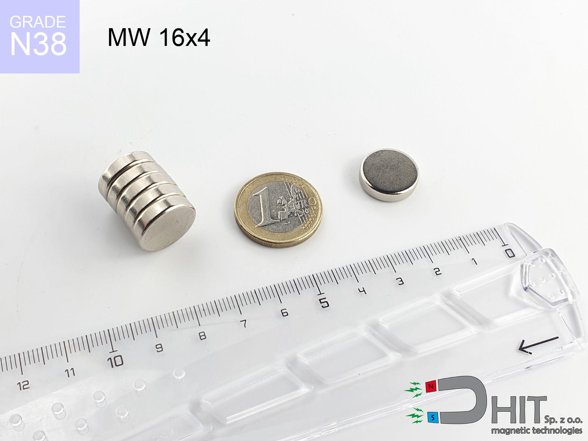
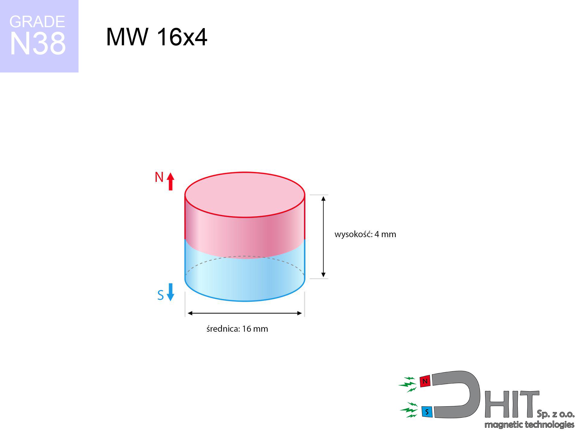
MW 16x4 / N38 - cylindrical magnet
cylindrical magnet
Catalog no 010034
GTIN/EAN: 5906301810339
Diameter Ø
16 mm [±0,1 mm]
Height
4 mm [±0,1 mm]
Weight
6.03 g
Magnetization Direction
↑ axial
Load capacity
4.43 kg / 43.46 N
Magnetic Induction
277.14 mT / 2771 Gs
Coating
[NiCuNi] Nickel
3.39 ZŁ with VAT / pcs + price for transport
2.76 ZŁ net + 23% VAT / pcs
bulk discounts:
Need more?
Pick up the phone and ask
+48 888 99 98 98
otherwise send us a note by means of
contact form
the contact page.
Parameters and shape of magnets can be calculated with our
our magnetic calculator.
Orders submitted before 14:00 will be dispatched today!
Technical specification - MW 16x4 / N38 - cylindrical magnet
Specification / characteristics - MW 16x4 / N38 - cylindrical magnet
| properties | values |
|---|---|
| Cat. no. | 010034 |
| GTIN/EAN | 5906301810339 |
| Production/Distribution | Dhit sp. z o.o. |
| Country of origin | Poland / China / Germany |
| Customs code | 85059029 |
| Diameter Ø | 16 mm [±0,1 mm] |
| Height | 4 mm [±0,1 mm] |
| Weight | 6.03 g |
| Magnetization Direction | ↑ axial |
| Load capacity ~ ? | 4.43 kg / 43.46 N |
| Magnetic Induction ~ ? | 277.14 mT / 2771 Gs |
| Coating | [NiCuNi] Nickel |
| Manufacturing Tolerance | ±0.1 mm |
Magnetic properties of material N38
| properties | values | units |
|---|---|---|
| remenance Br [min. - max.] ? | 12.2-12.6 | kGs |
| remenance Br [min. - max.] ? | 1220-1260 | mT |
| coercivity bHc ? | 10.8-11.5 | kOe |
| coercivity bHc ? | 860-915 | kA/m |
| actual internal force iHc | ≥ 12 | kOe |
| actual internal force iHc | ≥ 955 | kA/m |
| energy density [min. - max.] ? | 36-38 | BH max MGOe |
| energy density [min. - max.] ? | 287-303 | BH max KJ/m |
| max. temperature ? | ≤ 80 | °C |
Physical properties of sintered neodymium magnets Nd2Fe14B at 20°C
| properties | values | units |
|---|---|---|
| Vickers hardness | ≥550 | Hv |
| Density | ≥7.4 | g/cm3 |
| Curie Temperature TC | 312 - 380 | °C |
| Curie Temperature TF | 593 - 716 | °F |
| Specific resistance | 150 | μΩ⋅cm |
| Bending strength | 250 | MPa |
| Compressive strength | 1000~1100 | MPa |
| Thermal expansion parallel (∥) to orientation (M) | (3-4) x 10-6 | °C-1 |
| Thermal expansion perpendicular (⊥) to orientation (M) | -(1-3) x 10-6 | °C-1 |
| Young's modulus | 1.7 x 10⁴ | kg/mm² |
Engineering simulation of the product - data
Presented data represent the direct effect of a engineering simulation. Results are based on models for the material Nd2Fe14B. Actual performance might slightly differ from theoretical values. Please consider these calculations as a supplementary guide for designers.
Table 1: Static pull force (pull vs distance) - power drop
MW 16x4 / N38
| Distance (mm) | Induction (Gauss) / mT | Pull Force (kg/lbs/g/N) | Risk Status |
|---|---|---|---|
| 0 mm |
2771 Gs
277.1 mT
|
4.43 kg / 9.77 lbs
4430.0 g / 43.5 N
|
warning |
| 1 mm |
2517 Gs
251.7 mT
|
3.66 kg / 8.06 lbs
3656.3 g / 35.9 N
|
warning |
| 2 mm |
2216 Gs
221.6 mT
|
2.83 kg / 6.25 lbs
2834.9 g / 27.8 N
|
warning |
| 3 mm |
1906 Gs
190.6 mT
|
2.10 kg / 4.62 lbs
2096.1 g / 20.6 N
|
warning |
| 5 mm |
1348 Gs
134.8 mT
|
1.05 kg / 2.31 lbs
1048.6 g / 10.3 N
|
low risk |
| 10 mm |
542 Gs
54.2 mT
|
0.17 kg / 0.37 lbs
169.4 g / 1.7 N
|
low risk |
| 15 mm |
244 Gs
24.4 mT
|
0.03 kg / 0.08 lbs
34.2 g / 0.3 N
|
low risk |
| 20 mm |
125 Gs
12.5 mT
|
0.01 kg / 0.02 lbs
9.1 g / 0.1 N
|
low risk |
| 30 mm |
45 Gs
4.5 mT
|
0.00 kg / 0.00 lbs
1.1 g / 0.0 N
|
low risk |
| 50 mm |
11 Gs
1.1 mT
|
0.00 kg / 0.00 lbs
0.1 g / 0.0 N
|
low risk |
Table 2: Slippage force (wall)
MW 16x4 / N38
| Distance (mm) | Friction coefficient | Pull Force (kg/lbs/g/N) |
|---|---|---|
| 0 mm | Stal (~0.2) |
0.89 kg / 1.95 lbs
886.0 g / 8.7 N
|
| 1 mm | Stal (~0.2) |
0.73 kg / 1.61 lbs
732.0 g / 7.2 N
|
| 2 mm | Stal (~0.2) |
0.57 kg / 1.25 lbs
566.0 g / 5.6 N
|
| 3 mm | Stal (~0.2) |
0.42 kg / 0.93 lbs
420.0 g / 4.1 N
|
| 5 mm | Stal (~0.2) |
0.21 kg / 0.46 lbs
210.0 g / 2.1 N
|
| 10 mm | Stal (~0.2) |
0.03 kg / 0.07 lbs
34.0 g / 0.3 N
|
| 15 mm | Stal (~0.2) |
0.01 kg / 0.01 lbs
6.0 g / 0.1 N
|
| 20 mm | Stal (~0.2) |
0.00 kg / 0.00 lbs
2.0 g / 0.0 N
|
| 30 mm | Stal (~0.2) |
0.00 kg / 0.00 lbs
0.0 g / 0.0 N
|
| 50 mm | Stal (~0.2) |
0.00 kg / 0.00 lbs
0.0 g / 0.0 N
|
Table 3: Vertical assembly (shearing) - vertical pull
MW 16x4 / N38
| Surface type | Friction coefficient / % Mocy | Max load (kg/lbs/g/N) |
|---|---|---|
| Raw steel |
µ = 0.3
30% Nominalnej Siły
|
1.33 kg / 2.93 lbs
1329.0 g / 13.0 N
|
| Painted steel (standard) |
µ = 0.2
20% Nominalnej Siły
|
0.89 kg / 1.95 lbs
886.0 g / 8.7 N
|
| Oily/slippery steel |
µ = 0.1
10% Nominalnej Siły
|
0.44 kg / 0.98 lbs
443.0 g / 4.3 N
|
| Magnet with anti-slip rubber |
µ = 0.5
50% Nominalnej Siły
|
2.22 kg / 4.88 lbs
2215.0 g / 21.7 N
|
Table 4: Material efficiency (substrate influence) - power losses
MW 16x4 / N38
| Steel thickness (mm) | % power | Real pull force (kg/lbs/g/N) |
|---|---|---|
| 0.5 mm |
|
0.44 kg / 0.98 lbs
443.0 g / 4.3 N
|
| 1 mm |
|
1.11 kg / 2.44 lbs
1107.5 g / 10.9 N
|
| 2 mm |
|
2.22 kg / 4.88 lbs
2215.0 g / 21.7 N
|
| 3 mm |
|
3.32 kg / 7.32 lbs
3322.5 g / 32.6 N
|
| 5 mm |
|
4.43 kg / 9.77 lbs
4430.0 g / 43.5 N
|
| 10 mm |
|
4.43 kg / 9.77 lbs
4430.0 g / 43.5 N
|
| 11 mm |
|
4.43 kg / 9.77 lbs
4430.0 g / 43.5 N
|
| 12 mm |
|
4.43 kg / 9.77 lbs
4430.0 g / 43.5 N
|
Table 5: Working in heat (material behavior) - thermal limit
MW 16x4 / N38
| Ambient temp. (°C) | Power loss | Remaining pull (kg/lbs/g/N) | Status |
|---|---|---|---|
| 20 °C | 0.0% |
4.43 kg / 9.77 lbs
4430.0 g / 43.5 N
|
OK |
| 40 °C | -2.2% |
4.33 kg / 9.55 lbs
4332.5 g / 42.5 N
|
OK |
| 60 °C | -4.4% |
4.24 kg / 9.34 lbs
4235.1 g / 41.5 N
|
|
| 80 °C | -6.6% |
4.14 kg / 9.12 lbs
4137.6 g / 40.6 N
|
|
| 100 °C | -28.8% |
3.15 kg / 6.95 lbs
3154.2 g / 30.9 N
|
Table 6: Magnet-Magnet interaction (attraction) - field collision
MW 16x4 / N38
| Gap (mm) | Attraction (kg/lbs) (N-S) | Shear Force (kg/lbs/g/N) | Repulsion (kg/lbs) (N-N) |
|---|---|---|---|
| 0 mm |
9.51 kg / 20.98 lbs
4 379 Gs
|
1.43 kg / 3.15 lbs
1427 g / 14.0 N
|
N/A |
| 1 mm |
8.72 kg / 19.23 lbs
5 306 Gs
|
1.31 kg / 2.88 lbs
1309 g / 12.8 N
|
7.85 kg / 17.31 lbs
~0 Gs
|
| 2 mm |
7.85 kg / 17.31 lbs
5 034 Gs
|
1.18 kg / 2.60 lbs
1178 g / 11.6 N
|
7.07 kg / 15.58 lbs
~0 Gs
|
| 3 mm |
6.96 kg / 15.35 lbs
4 740 Gs
|
1.04 kg / 2.30 lbs
1044 g / 10.2 N
|
6.27 kg / 13.81 lbs
~0 Gs
|
| 5 mm |
5.26 kg / 11.60 lbs
4 121 Gs
|
0.79 kg / 1.74 lbs
789 g / 7.7 N
|
4.74 kg / 10.44 lbs
~0 Gs
|
| 10 mm |
2.25 kg / 4.97 lbs
2 696 Gs
|
0.34 kg / 0.74 lbs
338 g / 3.3 N
|
2.03 kg / 4.47 lbs
~0 Gs
|
| 20 mm |
0.36 kg / 0.80 lbs
1 083 Gs
|
0.05 kg / 0.12 lbs
55 g / 0.5 N
|
0.33 kg / 0.72 lbs
~0 Gs
|
| 50 mm |
0.01 kg / 0.01 lbs
143 Gs
|
0.00 kg / 0.00 lbs
1 g / 0.0 N
|
0.00 kg / 0.00 lbs
~0 Gs
|
| 60 mm |
0.00 kg / 0.01 lbs
89 Gs
|
0.00 kg / 0.00 lbs
0 g / 0.0 N
|
0.00 kg / 0.00 lbs
~0 Gs
|
| 70 mm |
0.00 kg / 0.00 lbs
59 Gs
|
0.00 kg / 0.00 lbs
0 g / 0.0 N
|
0.00 kg / 0.00 lbs
~0 Gs
|
| 80 mm |
0.00 kg / 0.00 lbs
41 Gs
|
0.00 kg / 0.00 lbs
0 g / 0.0 N
|
0.00 kg / 0.00 lbs
~0 Gs
|
| 90 mm |
0.00 kg / 0.00 lbs
29 Gs
|
0.00 kg / 0.00 lbs
0 g / 0.0 N
|
0.00 kg / 0.00 lbs
~0 Gs
|
| 100 mm |
0.00 kg / 0.00 lbs
22 Gs
|
0.00 kg / 0.00 lbs
0 g / 0.0 N
|
0.00 kg / 0.00 lbs
~0 Gs
|
Table 7: Safety (HSE) (implants) - warnings
MW 16x4 / N38
| Object / Device | Limit (Gauss) / mT | Safe distance |
|---|---|---|
| Pacemaker | 5 Gs (0.5 mT) | 7.0 cm |
| Hearing aid | 10 Gs (1.0 mT) | 5.5 cm |
| Mechanical watch | 20 Gs (2.0 mT) | 4.5 cm |
| Phone / Smartphone | 40 Gs (4.0 mT) | 3.5 cm |
| Remote | 50 Gs (5.0 mT) | 3.0 cm |
| Payment card | 400 Gs (40.0 mT) | 1.5 cm |
| HDD hard drive | 600 Gs (60.0 mT) | 1.0 cm |
Table 8: Collisions (kinetic energy) - warning
MW 16x4 / N38
| Start from (mm) | Speed (km/h) | Energy (J) | Predicted outcome |
|---|---|---|---|
| 10 mm |
27.98 km/h
(7.77 m/s)
|
0.18 J | |
| 30 mm |
47.35 km/h
(13.15 m/s)
|
0.52 J | |
| 50 mm |
61.12 km/h
(16.98 m/s)
|
0.87 J | |
| 100 mm |
86.44 km/h
(24.01 m/s)
|
1.74 J |
Table 9: Anti-corrosion coating durability
MW 16x4 / N38
| Technical parameter | Value / Description |
|---|---|
| Coating type | [NiCuNi] Nickel |
| Layer structure | Nickel - Copper - Nickel |
| Layer thickness | 10-20 µm |
| Salt spray test (SST) ? | 24 h |
| Recommended environment | Indoors only (dry) |
Table 10: Electrical data (Pc)
MW 16x4 / N38
| Parameter | Value | SI Unit / Description |
|---|---|---|
| Magnetic Flux | 6 192 Mx | 61.9 µWb |
| Pc Coefficient | 0.35 | Low (Flat) |
Table 11: Submerged application
MW 16x4 / N38
| Environment | Effective steel pull | Effect |
|---|---|---|
| Air (land) | 4.43 kg | Standard |
| Water (riverbed) |
5.07 kg
(+0.64 kg buoyancy gain)
|
+14.5% |
1. Sliding resistance
*Caution: On a vertical surface, the magnet retains only approx. 20-30% of its max power.
2. Efficiency vs thickness
*Thin steel (e.g. computer case) drastically limits the holding force.
3. Thermal stability
*For standard magnets, the max working temp is 80°C.
4. Demagnetization curve and operating point (B-H)
chart generated for the permeance coefficient Pc (Permeance Coefficient) = 0.35
The chart above illustrates the magnetic characteristics of the material within the second quadrant of the hysteresis loop. The solid red line represents the demagnetization curve (material potential), while the dashed blue line is the load line based on the magnet's geometry. The Pc (Permeance Coefficient), also known as the load line slope, is a dimensionless value that describes the relationship between the magnet's shape and its magnetic stability. The intersection of these two lines (the black dot) is the operating point — it determines the actual magnetic flux density generated by the magnet in this specific configuration. A higher Pc value means the magnet is more 'slender' (tall relative to its area), resulting in a higher operating point and better resistance to irreversible demagnetization caused by external fields or temperature. A value of 0.42 is relatively low (typical for flat magnets), meaning the operating point is closer to the 'knee' of the curve — caution is advised when operating at temperatures near the maximum limit to avoid strength loss.
Elemental analysis
| iron (Fe) | 64% – 68% |
| neodymium (Nd) | 29% – 32% |
| boron (B) | 1.1% – 1.2% |
| dysprosium (Dy) | 0.5% – 2.0% |
| coating (Ni-Cu-Ni) | < 0.05% |
Ecology and recycling (GPSR)
| recyclability (EoL) | 100% |
| recycled raw materials | ~10% (pre-cons) |
| carbon footprint | low / zredukowany |
| waste code (EWC) | 16 02 16 |
View also products

![SM 32x500 [2xM8] / N52 - magnetic separator](https://cdn3.dhit.pl/graphics/products/sm-32x500-2xm8-rub.jpg "SM 32x500 [2xM8] / N52 - magnetic separator")
![SM 32x375 [2xM8] / N52 - magnetic separator](https://cdn3.dhit.pl/graphics/products/sm-32x375-2xm8-mif.jpg "SM 32x375 [2xM8] / N52 - magnetic separator")
![UMP 97x40 [M8+M10] GW F300 Lina / N38 - search holder](https://cdn3.dhit.pl/graphics/products/ump-97x40-m8+m10-gw-f300-+lina-ful.jpg "UMP 97x40 [M8+M10] GW F300 Lina / N38 - search holder")
Advantages and disadvantages of Nd2Fe14B magnets.
Benefits
- They virtually do not lose strength, because even after 10 years the performance loss is only ~1% (in laboratory conditions),
- They feature excellent resistance to weakening of magnetic properties when exposed to opposing magnetic fields,
- By applying a lustrous layer of gold, the element has an proper look,
- The surface of neodymium magnets generates a strong magnetic field – this is a key feature,
- Made from properly selected components, these magnets show impressive resistance to high heat, enabling them to function (depending on their form) at temperatures up to 230°C and above...
- Thanks to flexibility in forming and the capacity to adapt to complex applications,
- Wide application in high-tech industry – they find application in hard drives, motor assemblies, advanced medical instruments, also complex engineering applications.
- Compactness – despite small sizes they generate large force, making them ideal for precision applications
Cons
- They are fragile upon heavy impacts. To avoid cracks, it is worth protecting magnets in a protective case. Such protection not only shields the magnet but also improves its resistance to damage
- When exposed to high temperature, neodymium magnets suffer a drop in power. Often, when the temperature exceeds 80°C, their power decreases (depending on the size, as well as shape of the magnet). For those who need magnets for extreme conditions, we offer [AH] versions withstanding up to 230°C
- They oxidize in a humid environment. For use outdoors we advise using waterproof magnets e.g. in rubber, plastic
- We suggest casing - magnetic mount, due to difficulties in producing nuts inside the magnet and complex shapes.
- Potential hazard resulting from small fragments of magnets pose a threat, in case of ingestion, which becomes key in the aspect of protecting the youngest. Furthermore, tiny parts of these devices can complicate diagnosis medical after entering the body.
- With large orders the cost of neodymium magnets is economically unviable,
Pull force analysis
Maximum lifting capacity of the magnet – what affects it?
- using a plate made of high-permeability steel, serving as a circuit closing element
- possessing a massiveness of at least 10 mm to ensure full flux closure
- with a surface cleaned and smooth
- with direct contact (without impurities)
- during detachment in a direction vertical to the mounting surface
- in temp. approx. 20°C
Practical lifting capacity: influencing factors
- Air gap (betwixt the magnet and the metal), because even a microscopic distance (e.g. 0.5 mm) can cause a decrease in force by up to 50% (this also applies to varnish, corrosion or debris).
- Force direction – declared lifting capacity refers to detachment vertically. When applying parallel force, the magnet holds significantly lower power (typically approx. 20-30% of maximum force).
- Steel thickness – too thin sheet does not close the flux, causing part of the power to be escaped to the other side.
- Metal type – not every steel attracts identically. Alloy additives weaken the attraction effect.
- Surface condition – ground elements ensure maximum contact, which improves field saturation. Uneven metal reduce efficiency.
- Thermal conditions – neodymium magnets have a sensitivity to temperature. When it is hot they are weaker, and at low temperatures gain strength (up to a certain limit).
Lifting capacity testing was conducted on a smooth plate of optimal thickness, under a perpendicular pulling force, whereas under attempts to slide the magnet the load capacity is reduced by as much as fivefold. In addition, even a minimal clearance between the magnet’s surface and the plate reduces the holding force.
Safe handling of neodymium magnets
Precision electronics
GPS units and smartphones are highly susceptible to magnetism. Direct contact with a powerful NdFeB magnet can ruin the internal compass in your phone.
Medical implants
Warning for patients: Powerful magnets disrupt medical devices. Keep minimum 30 cm distance or ask another person to handle the magnets.
Fragile material
Despite the nickel coating, neodymium is delicate and not impact-resistant. Avoid impacts, as the magnet may crumble into sharp, dangerous pieces.
Fire risk
Powder created during grinding of magnets is combustible. Do not drill into magnets unless you are an expert.
Operating temperature
Standard neodymium magnets (N-type) undergo demagnetization when the temperature exceeds 80°C. The loss of strength is permanent.
Swallowing risk
Only for adults. Tiny parts pose a choking risk, leading to serious injuries. Store out of reach of kids and pets.
Electronic devices
Very strong magnetic fields can erase data on payment cards, HDDs, and storage devices. Maintain a gap of min. 10 cm.
Handling guide
Before starting, check safety instructions. Sudden snapping can break the magnet or injure your hand. Be predictive.
Hand protection
Mind your fingers. Two large magnets will join instantly with a force of massive weight, destroying anything in their path. Be careful!
Warning for allergy sufferers
Certain individuals have a contact allergy to Ni, which is the common plating for NdFeB magnets. Prolonged contact can result in an allergic reaction. We suggest wear protective gloves.
Tabela kosztu i czasu dostawy
Płatność przed wysyłką:

GLS kurier
Przesyłka będzie u Ciebie za 2-3 dni
14.99 ZŁ

InPost Paczkomaty 24/7
Przesyłka będzie u Ciebie za 1-2 dni
12.30 ZŁ
Płatność przy odbiorze (pobranie):
GLS kurier
Przesyłka będzie u Ciebie za 1-2 dni
23.00 ZŁ
Rate the product
Your rating