

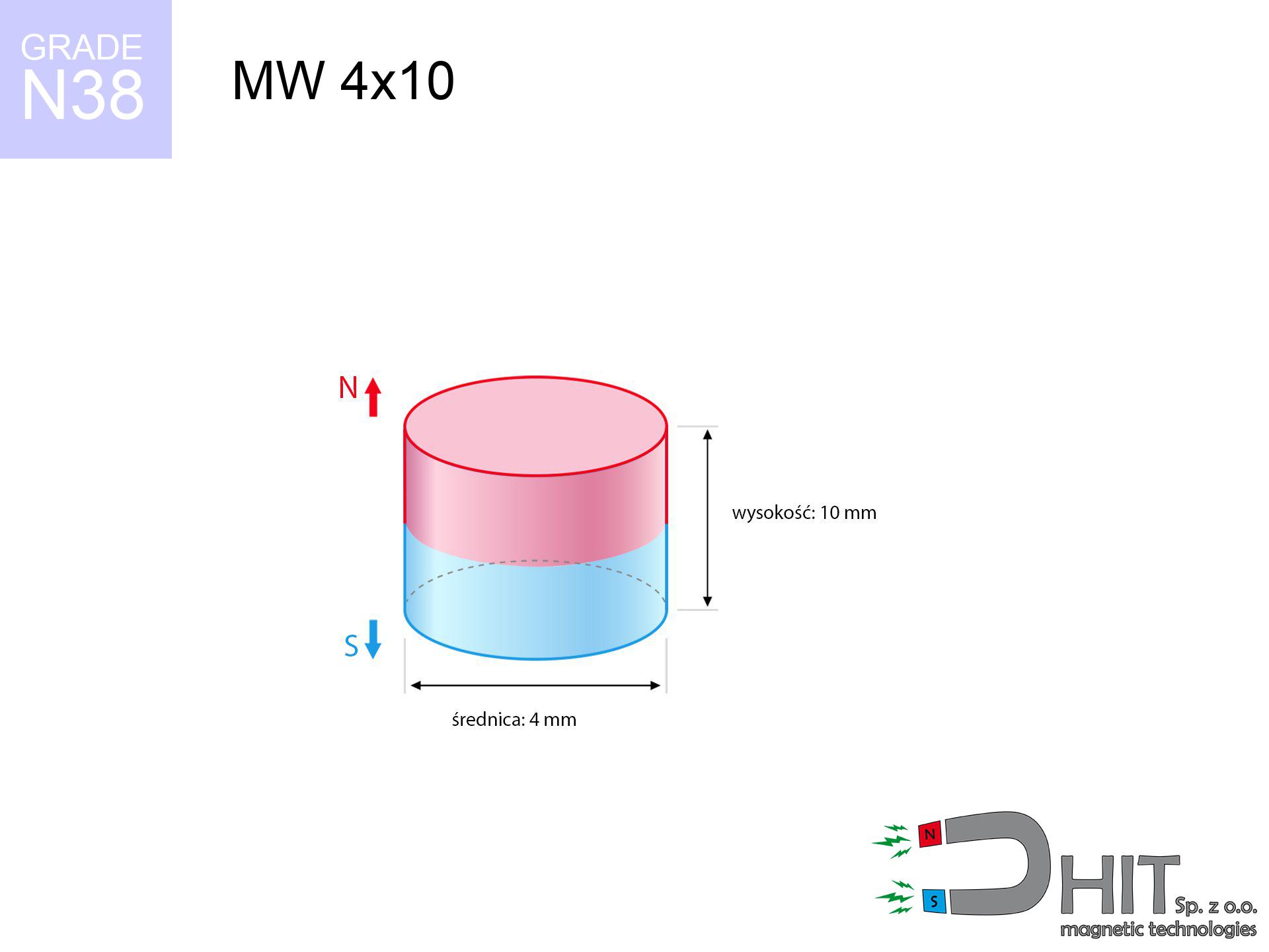
MW 4x10 / N38 - cylindrical magnet
cylindrical magnet
Catalog no 010075
GTIN/EAN: 5906301810742
Diameter Ø
4 mm [±0,1 mm]
Height
10 mm [±0,1 mm]
Weight
0.94 g
Magnetization Direction
↑ axial
Load capacity
0.32 kg / 3.16 N
Magnetic Induction
606.05 mT / 6061 Gs
Coating
[NiCuNi] Nickel
0.800 ZŁ with VAT / pcs + price for transport
0.650 ZŁ net + 23% VAT / pcs
bulk discounts:
Need more?Engineering report for this magnet
Full PDF analysis: pull and shear force, effect of distance, temperature and plate thickness, safety distances and the demagnetization curve.
Call us now
+48 22 499 98 98
or get in touch through
our online form
the contact page.
Force as well as form of neodymium magnets can be estimated using our
online calculation tool.
Same-day processing for orders placed before 14:00.
Technical parameters - MW 4x10 / N38 - cylindrical magnet
Specification / characteristics - MW 4x10 / N38 - cylindrical magnet
| properties | values |
|---|---|
| Cat. no. | 010075 |
| GTIN/EAN | 5906301810742 |
| Production/Distribution | Dhit sp. z o.o. |
| Country of origin | Poland / China / Germany |
| Customs code | 85059029 |
| Diameter Ø | 4 mm [±0,1 mm] |
| Height | 10 mm [±0,1 mm] |
| Weight | 0.94 g |
| Magnetization Direction | ↑ axial |
| Load capacity ~ ? | 0.32 kg / 3.16 N |
| Magnetic Induction ~ ? | 606.05 mT / 6061 Gs |
| Coating | [NiCuNi] Nickel |
| Manufacturing Tolerance | ±0.1 mm |
Magnetic properties of material N38
| properties | values | units |
|---|---|---|
| remenance Br [min. - max.] ? | 12.2-12.6 | kGs |
| remenance Br [min. - max.] ? | 1220-1260 | mT |
| coercivity bHc ? | 10.8-11.5 | kOe |
| coercivity bHc ? | 860-915 | kA/m |
| actual internal force iHc | ≥ 12 | kOe |
| actual internal force iHc | ≥ 955 | kA/m |
| energy density [min. - max.] ? | 36-38 | BH max MGOe |
| energy density [min. - max.] ? | 287-303 | BH max KJ/m |
| max. temperature ? | ≤ 80 | °C |
Physical properties of sintered neodymium magnets Nd2Fe14B at 20°C
| properties | values | units |
|---|---|---|
| Vickers hardness | ≥550 | Hv |
| Density | ≥7.4 | g/cm3 |
| Curie Temperature TC | 312 - 380 | °C |
| Curie Temperature TF | 593 - 716 | °F |
| Specific resistance | 150 | μΩ⋅cm |
| Bending strength | 250 | MPa |
| Compressive strength | 1000~1100 | MPa |
| Thermal expansion parallel (∥) to orientation (M) | (3-4) x 10-6 | °C-1 |
| Thermal expansion perpendicular (⊥) to orientation (M) | -(1-3) x 10-6 | °C-1 |
| Young's modulus | 1.7 x 10⁴ | kg/mm² |
Engineering simulation of the assembly - data
The following data represent the outcome of a engineering analysis. Results were calculated on models for the class Nd2Fe14B. Real-world parameters might slightly differ from theoretical values. Treat these calculations as a preliminary roadmap for designers.
Table 1: Static pull force (force vs gap) - interaction chart
MW 4x10 / N38
| Distance (mm) | Induction (Gauss) / mT | Pull Force (kg/lbs/g/N) | Risk Status |
|---|---|---|---|
| 0 mm |
6049 Gs
604.9 mT
|
0.32 kg / 0.71 pounds
320.0 g / 3.1 N
|
safe |
| 1 mm |
3327 Gs
332.7 mT
|
0.10 kg / 0.21 pounds
96.8 g / 0.9 N
|
safe |
| 2 mm |
1732 Gs
173.2 mT
|
0.03 kg / 0.06 pounds
26.2 g / 0.3 N
|
safe |
| 3 mm |
969 Gs
96.9 mT
|
0.01 kg / 0.02 pounds
8.2 g / 0.1 N
|
safe |
| 5 mm |
389 Gs
38.9 mT
|
0.00 kg / 0.00 pounds
1.3 g / 0.0 N
|
safe |
| 10 mm |
90 Gs
9.0 mT
|
0.00 kg / 0.00 pounds
0.1 g / 0.0 N
|
safe |
| 15 mm |
35 Gs
3.5 mT
|
0.00 kg / 0.00 pounds
0.0 g / 0.0 N
|
safe |
| 20 mm |
17 Gs
1.7 mT
|
0.00 kg / 0.00 pounds
0.0 g / 0.0 N
|
safe |
| 30 mm |
6 Gs
0.6 mT
|
0.00 kg / 0.00 pounds
0.0 g / 0.0 N
|
safe |
| 50 mm |
2 Gs
0.2 mT
|
0.00 kg / 0.00 pounds
0.0 g / 0.0 N
|
safe |
Table 2: Sliding load (vertical surface)
MW 4x10 / N38
| Distance (mm) | Friction coefficient | Pull Force (kg/lbs/g/N) |
|---|---|---|
| 0 mm | Stal (~0.2) |
0.06 kg / 0.14 pounds
64.0 g / 0.6 N
|
| 1 mm | Stal (~0.2) |
0.02 kg / 0.04 pounds
20.0 g / 0.2 N
|
| 2 mm | Stal (~0.2) |
0.01 kg / 0.01 pounds
6.0 g / 0.1 N
|
| 3 mm | Stal (~0.2) |
0.00 kg / 0.00 pounds
2.0 g / 0.0 N
|
| 5 mm | Stal (~0.2) |
0.00 kg / 0.00 pounds
0.0 g / 0.0 N
|
| 10 mm | Stal (~0.2) |
0.00 kg / 0.00 pounds
0.0 g / 0.0 N
|
| 15 mm | Stal (~0.2) |
0.00 kg / 0.00 pounds
0.0 g / 0.0 N
|
| 20 mm | Stal (~0.2) |
0.00 kg / 0.00 pounds
0.0 g / 0.0 N
|
| 30 mm | Stal (~0.2) |
0.00 kg / 0.00 pounds
0.0 g / 0.0 N
|
| 50 mm | Stal (~0.2) |
0.00 kg / 0.00 pounds
0.0 g / 0.0 N
|
Table 3: Vertical assembly (sliding) - behavior on slippery surfaces
MW 4x10 / N38
| Surface type | Friction coefficient / % Mocy | Max load (kg/lbs/g/N) |
|---|---|---|
| Raw steel |
µ = 0.3
30% Nominalnej Siły
|
0.10 kg / 0.21 pounds
96.0 g / 0.9 N
|
| Painted steel (standard) |
µ = 0.2
20% Nominalnej Siły
|
0.06 kg / 0.14 pounds
64.0 g / 0.6 N
|
| Oily/slippery steel |
µ = 0.1
10% Nominalnej Siły
|
0.03 kg / 0.07 pounds
32.0 g / 0.3 N
|
| Magnet with anti-slip rubber |
µ = 0.5
50% Nominalnej Siły
|
0.16 kg / 0.35 pounds
160.0 g / 1.6 N
|
Table 4: Steel thickness (saturation) - power losses
MW 4x10 / N38
| Steel thickness (mm) | % power | Real pull force (kg/lbs/g/N) |
|---|---|---|
| 0.5 mm |
|
0.03 kg / 0.07 pounds
32.0 g / 0.3 N
|
| 1 mm |
|
0.08 kg / 0.18 pounds
80.0 g / 0.8 N
|
| 2 mm |
|
0.16 kg / 0.35 pounds
160.0 g / 1.6 N
|
| 3 mm |
|
0.24 kg / 0.53 pounds
240.0 g / 2.4 N
|
| 5 mm |
|
0.32 kg / 0.71 pounds
320.0 g / 3.1 N
|
| 10 mm |
|
0.32 kg / 0.71 pounds
320.0 g / 3.1 N
|
| 11 mm |
|
0.32 kg / 0.71 pounds
320.0 g / 3.1 N
|
| 12 mm |
|
0.32 kg / 0.71 pounds
320.0 g / 3.1 N
|
Table 5: Thermal stability (stability) - thermal limit
MW 4x10 / N38
| Ambient temp. (°C) | Power loss | Remaining pull (kg/lbs/g/N) | Status |
|---|---|---|---|
| 20 °C | 0.0% |
0.32 kg / 0.71 pounds
320.0 g / 3.1 N
|
OK |
| 40 °C | -2.2% |
0.31 kg / 0.69 pounds
313.0 g / 3.1 N
|
OK |
| 60 °C | -4.4% |
0.31 kg / 0.67 pounds
305.9 g / 3.0 N
|
OK |
| 80 °C | -6.6% |
0.30 kg / 0.66 pounds
298.9 g / 2.9 N
|
|
| 100 °C | -28.8% |
0.23 kg / 0.50 pounds
227.8 g / 2.2 N
|
Table 6: Magnet-Magnet interaction (attraction) - forces in the system
MW 4x10 / N38
| Gap (mm) | Attraction (kg/lbs) (N-S) | Lateral Force (kg/lbs/g/N) | Repulsion (kg/lbs) (N-N) |
|---|---|---|---|
| 0 mm |
2.83 kg / 6.25 pounds
6 138 Gs
|
0.43 kg / 0.94 pounds
425 g / 4.2 N
|
N/A |
| 1 mm |
1.63 kg / 3.59 pounds
9 174 Gs
|
0.24 kg / 0.54 pounds
244 g / 2.4 N
|
1.47 kg / 3.23 pounds
~0 Gs
|
| 2 mm |
0.86 kg / 1.89 pounds
6 655 Gs
|
0.13 kg / 0.28 pounds
129 g / 1.3 N
|
0.77 kg / 1.70 pounds
~0 Gs
|
| 3 mm |
0.44 kg / 0.97 pounds
4 777 Gs
|
0.07 kg / 0.15 pounds
66 g / 0.7 N
|
0.40 kg / 0.88 pounds
~0 Gs
|
| 5 mm |
0.13 kg / 0.28 pounds
2 561 Gs
|
0.02 kg / 0.04 pounds
19 g / 0.2 N
|
0.11 kg / 0.25 pounds
~0 Gs
|
| 10 mm |
0.01 kg / 0.03 pounds
778 Gs
|
0.00 kg / 0.00 pounds
2 g / 0.0 N
|
0.01 kg / 0.02 pounds
~0 Gs
|
| 20 mm |
0.00 kg / 0.00 pounds
179 Gs
|
0.00 kg / 0.00 pounds
0 g / 0.0 N
|
0.00 kg / 0.00 pounds
~0 Gs
|
| 50 mm |
0.00 kg / 0.00 pounds
19 Gs
|
0.00 kg / 0.00 pounds
0 g / 0.0 N
|
0.00 kg / 0.00 pounds
~0 Gs
|
| 60 mm |
0.00 kg / 0.00 pounds
12 Gs
|
0.00 kg / 0.00 pounds
0 g / 0.0 N
|
0.00 kg / 0.00 pounds
~0 Gs
|
| 70 mm |
0.00 kg / 0.00 pounds
8 Gs
|
0.00 kg / 0.00 pounds
0 g / 0.0 N
|
0.00 kg / 0.00 pounds
~0 Gs
|
| 80 mm |
0.00 kg / 0.00 pounds
6 Gs
|
0.00 kg / 0.00 pounds
0 g / 0.0 N
|
0.00 kg / 0.00 pounds
~0 Gs
|
| 90 mm |
0.00 kg / 0.00 pounds
4 Gs
|
0.00 kg / 0.00 pounds
0 g / 0.0 N
|
0.00 kg / 0.00 pounds
~0 Gs
|
| 100 mm |
0.00 kg / 0.00 pounds
3 Gs
|
0.00 kg / 0.00 pounds
0 g / 0.0 N
|
0.00 kg / 0.00 pounds
~0 Gs
|
Table 7: Safety (HSE) (electronics) - precautionary measures
MW 4x10 / N38
| Object / Device | Limit (Gauss) / mT | Safe distance |
|---|---|---|
| Pacemaker | 5 Gs (0.5 mT) | 3.5 cm |
| Hearing aid | 10 Gs (1.0 mT) | 2.5 cm |
| Mechanical watch | 20 Gs (2.0 mT) | 2.0 cm |
| Mobile device | 40 Gs (4.0 mT) | 1.5 cm |
| Remote | 50 Gs (5.0 mT) | 1.5 cm |
| Payment card | 400 Gs (40.0 mT) | 0.5 cm |
| HDD hard drive | 600 Gs (60.0 mT) | 0.5 cm |
Table 8: Dynamics (cracking risk) - warning
MW 4x10 / N38
| Start from (mm) | Speed (km/h) | Energy (J) | Predicted outcome |
|---|---|---|---|
| 10 mm |
18.61 km/h
(5.17 m/s)
|
0.01 J | |
| 30 mm |
32.23 km/h
(8.95 m/s)
|
0.04 J | |
| 50 mm |
41.61 km/h
(11.56 m/s)
|
0.06 J | |
| 100 mm |
58.84 km/h
(16.35 m/s)
|
0.13 J |
Table 9: Anti-corrosion coating durability
MW 4x10 / N38
| Technical parameter | Value / Description |
|---|---|
| Coating type | [NiCuNi] Nickel |
| Layer structure | Nickel - Copper - Nickel |
| Layer thickness | 10-20 µm |
| Salt spray test (SST) ? | 24 h |
| Recommended environment | Indoors only (dry) |
Table 10: Electrical data (Flux)
MW 4x10 / N38
| Parameter | Value | SI Unit / Description |
|---|---|---|
| Magnetic Flux | 864 Mx | 8.6 µWb |
| Pc Coefficient | 1.31 | High (Stable) |
Table 11: Hydrostatics and buoyancy
MW 4x10 / N38
| Environment | Effective steel pull | Effect |
|---|---|---|
| Air (land) | 0.32 kg | Standard |
| Water (riverbed) |
0.37 kg
(+0.05 kg buoyancy gain)
|
+14.5% |
1. Shear force
*Note: On a vertical wall, the magnet retains only ~20% of its nominal pull.
2. Plate thickness effect
*Thin steel (e.g. 0.5mm PC case) significantly limits the holding force.
3. Temperature resistance
*For N38 material, the safety limit is 80°C.
4. Demagnetization curve and operating point (B-H)
chart generated for the permeance coefficient Pc (Permeance Coefficient) = 1.31
The chart above illustrates the magnetic characteristics of the material within the second quadrant of the hysteresis loop. The solid red line represents the demagnetization curve (material potential), while the dashed blue line is the load line based on the magnet's geometry. The Pc (Permeance Coefficient), also known as the load line slope, is a dimensionless value that describes the relationship between the magnet's shape and its magnetic stability. The intersection of these two lines (the black dot) is the operating point — it determines the actual magnetic flux density generated by the magnet in this specific configuration. A higher Pc value means the magnet is more 'slender' (tall relative to its area), resulting in a higher operating point and better resistance to irreversible demagnetization caused by external fields or temperature. A value of 0.42 is relatively low (typical for flat magnets), meaning the operating point is closer to the 'knee' of the curve — caution is advised when operating at temperatures near the maximum limit to avoid strength loss.
Material specification
| iron (Fe) | 64% – 68% |
| neodymium (Nd) | 29% – 32% |
| boron (B) | 1.1% – 1.2% |
| dysprosium (Dy) | 0.5% – 2.0% |
| coating (Ni-Cu-Ni) | < 0.05% |
Ecology and recycling (GPSR)
| recyclability (EoL) | 100% |
| recycled raw materials | ~10% (pre-cons) |
| carbon footprint | low / zredukowany |
| waste code (EWC) | 16 02 16 |
Other deals


Advantages as well as disadvantages of neodymium magnets.
Pros
- They have stable power, and over nearly 10 years their performance decreases symbolically – ~1% (according to theory),
- They feature excellent resistance to weakening of magnetic properties as a result of external magnetic sources,
- The use of an metallic coating of noble metals (nickel, gold, silver) causes the element to present itself better,
- Magnetic induction on the working part of the magnet remains impressive,
- Through (appropriate) combination of ingredients, they can achieve high thermal resistance, enabling operation at temperatures reaching 230°C and above...
- In view of the ability of precise forming and customization to unique projects, magnetic components can be modeled in a wide range of geometric configurations, which expands the range of possible applications,
- Key role in modern technologies – they are utilized in computer drives, electromotive mechanisms, precision medical tools, as well as technologically advanced constructions.
- Thanks to efficiency per cm³, small magnets offer high operating force, with minimal size,
Limitations
- Susceptibility to cracking is one of their disadvantages. Upon strong impact they can fracture. We advise keeping them in a special holder, which not only protects them against impacts but also raises their durability
- Neodymium magnets decrease their strength under the influence of heating. As soon as 80°C is exceeded, many of them start losing their power. Therefore, we recommend our special magnets marked [AH], which maintain stability even at temperatures up to 230°C
- They oxidize in a humid environment. For use outdoors we suggest using waterproof magnets e.g. in rubber, plastic
- We suggest casing - magnetic mount, due to difficulties in producing threads inside the magnet and complicated forms.
- Possible danger related to microscopic parts of magnets can be dangerous, when accidentally swallowed, which is particularly important in the context of child health protection. Additionally, small components of these magnets can disrupt the diagnostic process medical in case of swallowing.
- High unit price – neodymium magnets have a higher price than other types of magnets (e.g. ferrite), which increases costs of application in large quantities
Pull force analysis
Maximum holding power of the magnet – what it depends on?
- on a block made of structural steel, effectively closing the magnetic flux
- whose thickness is min. 10 mm
- characterized by smoothness
- without any clearance between the magnet and steel
- during detachment in a direction vertical to the plane
- in temp. approx. 20°C
What influences lifting capacity in practice
- Distance – the presence of any layer (paint, dirt, gap) acts as an insulator, which reduces power steeply (even by 50% at 0.5 mm).
- Load vector – maximum parameter is available only during pulling at a 90° angle. The force required to slide of the magnet along the surface is standardly several times lower (approx. 1/5 of the lifting capacity).
- Element thickness – to utilize 100% power, the steel must be adequately massive. Paper-thin metal restricts the attraction force (the magnet "punches through" it).
- Steel type – low-carbon steel gives the best results. Alloy steels decrease magnetic properties and holding force.
- Base smoothness – the more even the plate, the better the adhesion and stronger the hold. Unevenness acts like micro-gaps.
- Thermal conditions – neodymium magnets have a sensitivity to temperature. When it is hot they are weaker, and in frost they can be stronger (up to a certain limit).
Holding force was measured on a smooth steel plate of 20 mm thickness, when the force acted perpendicularly, whereas under shearing force the load capacity is reduced by as much as fivefold. In addition, even a small distance between the magnet’s surface and the plate lowers the lifting capacity.
Precautions when working with neodymium magnets
Data carriers
Do not bring magnets close to a purse, computer, or TV. The magnetic field can permanently damage these devices and erase data from cards.
Danger to the youngest
These products are not suitable for play. Accidental ingestion of a few magnets can lead to them attracting across intestines, which poses a direct threat to life and requires urgent medical intervention.
Crushing risk
Protect your hands. Two powerful magnets will snap together immediately with a force of several hundred kilograms, crushing everything in their path. Exercise extreme caution!
Power loss in heat
Do not overheat. Neodymium magnets are sensitive to heat. If you need resistance above 80°C, ask us about HT versions (H, SH, UH).
Do not underestimate power
Before starting, check safety instructions. Uncontrolled attraction can break the magnet or hurt your hand. Think ahead.
Beware of splinters
Neodymium magnets are ceramic materials, meaning they are fragile like glass. Impact of two magnets will cause them cracking into shards.
Flammability
Fire warning: Rare earth powder is explosive. Do not process magnets without safety gear as this may cause fire.
Health Danger
People with a ICD must keep an absolute distance from magnets. The magnetic field can stop the operation of the implant.
Precision electronics
An intense magnetic field disrupts the operation of magnetometers in smartphones and navigation systems. Keep magnets close to a smartphone to prevent breaking the sensors.
Avoid contact if allergic
Some people experience a contact allergy to Ni, which is the standard coating for neodymium magnets. Extended handling can result in a rash. It is best to wear protective gloves.
Tabela kosztu i czasu dostawy
Płatność przed wysyłką:

GLS kurier
Przesyłka będzie u Ciebie za 2-3 dni
14.99 ZŁ

InPost Paczkomaty 24/7
Przesyłka będzie u Ciebie za 1-2 dni
12.30 ZŁ
Płatność przy odbiorze (pobranie):
GLS kurier
Przesyłka będzie u Ciebie za 1-2 dni
23.00 ZŁ
Rate the product
Your rating