

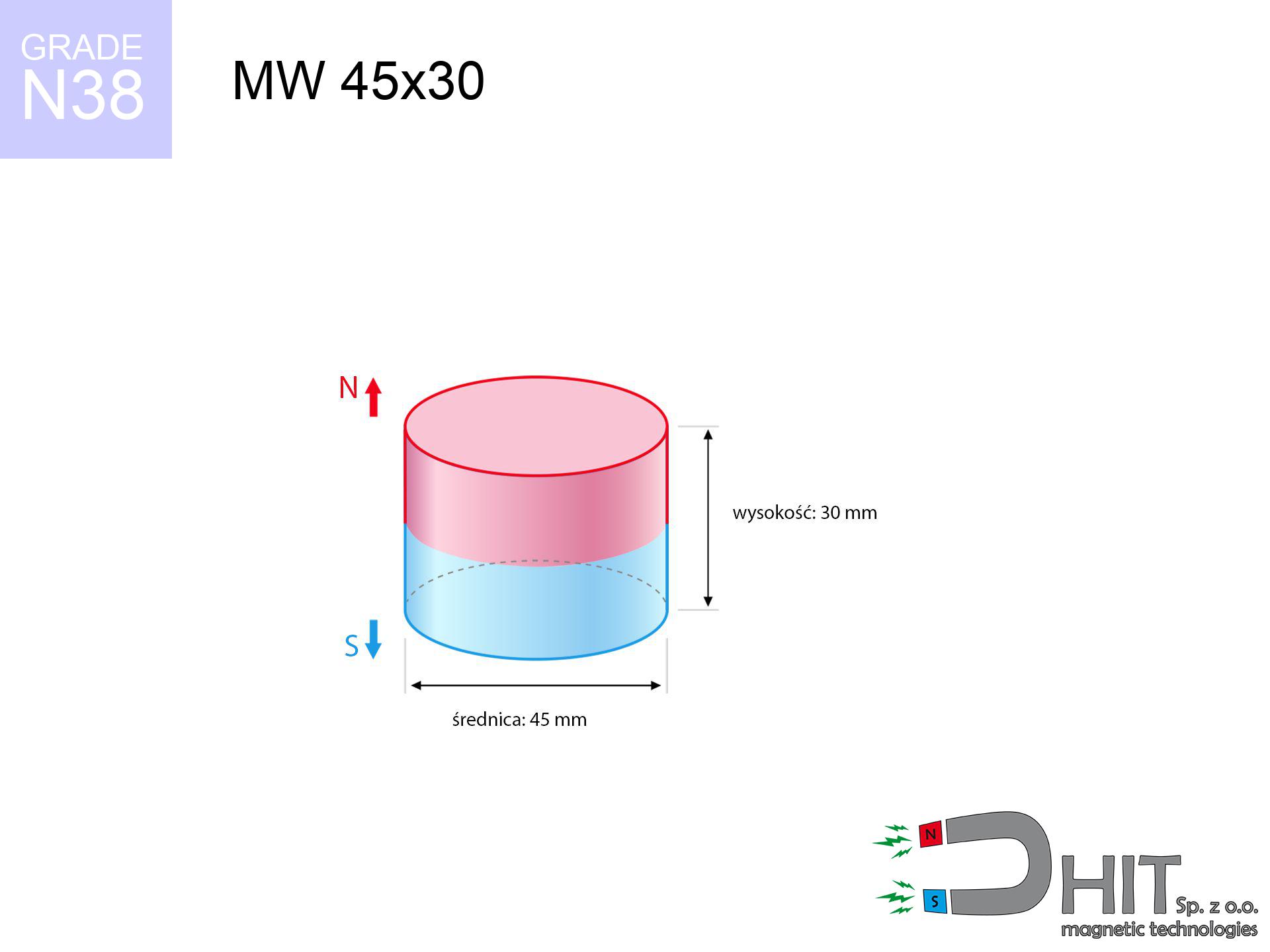
MW 45x30 / N38 - cylindrical magnet
cylindrical magnet
Catalog no 010073
GTIN/EAN: 5906301810728
Diameter Ø
45 mm [±0,1 mm]
Height
30 mm [±0,1 mm]
Weight
357.85 g
Magnetization Direction
↑ axial
Load capacity
69.46 kg / 681.39 N
Magnetic Induction
495.87 mT / 4959 Gs
Coating
[NiCuNi] Nickel
136.80 ZŁ with VAT / pcs + price for transport
111.22 ZŁ net + 23% VAT / pcs
bulk discounts:
Need more?
Pick up the phone and ask
+48 888 99 98 98
alternatively drop us a message using
contact form
our website.
Parameters as well as form of magnets can be estimated on our
our magnetic calculator.
Same-day processing for orders placed before 14:00.
Product card - MW 45x30 / N38 - cylindrical magnet
Specification / characteristics - MW 45x30 / N38 - cylindrical magnet
| properties | values |
|---|---|
| Cat. no. | 010073 |
| GTIN/EAN | 5906301810728 |
| Production/Distribution | Dhit sp. z o.o. |
| Country of origin | Poland / China / Germany |
| Customs code | 85059029 |
| Diameter Ø | 45 mm [±0,1 mm] |
| Height | 30 mm [±0,1 mm] |
| Weight | 357.85 g |
| Magnetization Direction | ↑ axial |
| Load capacity ~ ? | 69.46 kg / 681.39 N |
| Magnetic Induction ~ ? | 495.87 mT / 4959 Gs |
| Coating | [NiCuNi] Nickel |
| Manufacturing Tolerance | ±0.1 mm |
Magnetic properties of material N38
| properties | values | units |
|---|---|---|
| remenance Br [min. - max.] ? | 12.2-12.6 | kGs |
| remenance Br [min. - max.] ? | 1220-1260 | mT |
| coercivity bHc ? | 10.8-11.5 | kOe |
| coercivity bHc ? | 860-915 | kA/m |
| actual internal force iHc | ≥ 12 | kOe |
| actual internal force iHc | ≥ 955 | kA/m |
| energy density [min. - max.] ? | 36-38 | BH max MGOe |
| energy density [min. - max.] ? | 287-303 | BH max KJ/m |
| max. temperature ? | ≤ 80 | °C |
Physical properties of sintered neodymium magnets Nd2Fe14B at 20°C
| properties | values | units |
|---|---|---|
| Vickers hardness | ≥550 | Hv |
| Density | ≥7.4 | g/cm3 |
| Curie Temperature TC | 312 - 380 | °C |
| Curie Temperature TF | 593 - 716 | °F |
| Specific resistance | 150 | μΩ⋅cm |
| Bending strength | 250 | MPa |
| Compressive strength | 1000~1100 | MPa |
| Thermal expansion parallel (∥) to orientation (M) | (3-4) x 10-6 | °C-1 |
| Thermal expansion perpendicular (⊥) to orientation (M) | -(1-3) x 10-6 | °C-1 |
| Young's modulus | 1.7 x 10⁴ | kg/mm² |
Technical simulation of the magnet - report
Presented data constitute the direct effect of a mathematical calculation. Results were calculated on algorithms for the class Nd2Fe14B. Operational conditions might slightly deviate from the simulation results. Treat these data as a preliminary roadmap when designing systems.
Table 1: Static force (force vs distance) - characteristics
MW 45x30 / N38
| Distance (mm) | Induction (Gauss) / mT | Pull Force (kg/lbs/g/N) | Risk Status |
|---|---|---|---|
| 0 mm |
4958 Gs
495.8 mT
|
69.46 kg / 153.13 LBS
69460.0 g / 681.4 N
|
critical level |
| 1 mm |
4742 Gs
474.2 mT
|
63.55 kg / 140.11 LBS
63553.9 g / 623.5 N
|
critical level |
| 2 mm |
4523 Gs
452.3 mT
|
57.81 kg / 127.44 LBS
57805.8 g / 567.1 N
|
critical level |
| 3 mm |
4303 Gs
430.3 mT
|
52.33 kg / 115.36 LBS
52327.7 g / 513.3 N
|
critical level |
| 5 mm |
3870 Gs
387.0 mT
|
42.33 kg / 93.32 LBS
42329.9 g / 415.3 N
|
critical level |
| 10 mm |
2886 Gs
288.6 mT
|
23.53 kg / 51.88 LBS
23531.8 g / 230.8 N
|
critical level |
| 15 mm |
2106 Gs
210.6 mT
|
12.54 kg / 27.64 LBS
12537.0 g / 123.0 N
|
critical level |
| 20 mm |
1535 Gs
153.5 mT
|
6.66 kg / 14.68 LBS
6657.1 g / 65.3 N
|
warning |
| 30 mm |
845 Gs
84.5 mT
|
2.02 kg / 4.45 LBS
2018.9 g / 19.8 N
|
warning |
| 50 mm |
315 Gs
31.5 mT
|
0.28 kg / 0.62 LBS
279.5 g / 2.7 N
|
low risk |
Table 2: Shear hold (vertical surface)
MW 45x30 / N38
| Distance (mm) | Friction coefficient | Pull Force (kg/lbs/g/N) |
|---|---|---|
| 0 mm | Stal (~0.2) |
13.89 kg / 30.63 LBS
13892.0 g / 136.3 N
|
| 1 mm | Stal (~0.2) |
12.71 kg / 28.02 LBS
12710.0 g / 124.7 N
|
| 2 mm | Stal (~0.2) |
11.56 kg / 25.49 LBS
11562.0 g / 113.4 N
|
| 3 mm | Stal (~0.2) |
10.47 kg / 23.07 LBS
10466.0 g / 102.7 N
|
| 5 mm | Stal (~0.2) |
8.47 kg / 18.66 LBS
8466.0 g / 83.1 N
|
| 10 mm | Stal (~0.2) |
4.71 kg / 10.37 LBS
4706.0 g / 46.2 N
|
| 15 mm | Stal (~0.2) |
2.51 kg / 5.53 LBS
2508.0 g / 24.6 N
|
| 20 mm | Stal (~0.2) |
1.33 kg / 2.94 LBS
1332.0 g / 13.1 N
|
| 30 mm | Stal (~0.2) |
0.40 kg / 0.89 LBS
404.0 g / 4.0 N
|
| 50 mm | Stal (~0.2) |
0.06 kg / 0.12 LBS
56.0 g / 0.5 N
|
Table 3: Wall mounting (shearing) - vertical pull
MW 45x30 / N38
| Surface type | Friction coefficient / % Mocy | Max load (kg/lbs/g/N) |
|---|---|---|
| Raw steel |
µ = 0.3
30% Nominalnej Siły
|
20.84 kg / 45.94 LBS
20838.0 g / 204.4 N
|
| Painted steel (standard) |
µ = 0.2
20% Nominalnej Siły
|
13.89 kg / 30.63 LBS
13892.0 g / 136.3 N
|
| Oily/slippery steel |
µ = 0.1
10% Nominalnej Siły
|
6.95 kg / 15.31 LBS
6946.0 g / 68.1 N
|
| Magnet with anti-slip rubber |
µ = 0.5
50% Nominalnej Siły
|
34.73 kg / 76.57 LBS
34730.0 g / 340.7 N
|
Table 4: Material efficiency (substrate influence) - power losses
MW 45x30 / N38
| Steel thickness (mm) | % power | Real pull force (kg/lbs/g/N) |
|---|---|---|
| 0.5 mm |
|
2.32 kg / 5.10 LBS
2315.3 g / 22.7 N
|
| 1 mm |
|
5.79 kg / 12.76 LBS
5788.3 g / 56.8 N
|
| 2 mm |
|
11.58 kg / 25.52 LBS
11576.7 g / 113.6 N
|
| 3 mm |
|
17.37 kg / 38.28 LBS
17365.0 g / 170.4 N
|
| 5 mm |
|
28.94 kg / 63.81 LBS
28941.7 g / 283.9 N
|
| 10 mm |
|
57.88 kg / 127.61 LBS
57883.3 g / 567.8 N
|
| 11 mm |
|
63.67 kg / 140.37 LBS
63671.7 g / 624.6 N
|
| 12 mm |
|
69.46 kg / 153.13 LBS
69460.0 g / 681.4 N
|
Table 5: Working in heat (material behavior) - thermal limit
MW 45x30 / N38
| Ambient temp. (°C) | Power loss | Remaining pull (kg/lbs/g/N) | Status |
|---|---|---|---|
| 20 °C | 0.0% |
69.46 kg / 153.13 LBS
69460.0 g / 681.4 N
|
OK |
| 40 °C | -2.2% |
67.93 kg / 149.76 LBS
67931.9 g / 666.4 N
|
OK |
| 60 °C | -4.4% |
66.40 kg / 146.40 LBS
66403.8 g / 651.4 N
|
OK |
| 80 °C | -6.6% |
64.88 kg / 143.03 LBS
64875.6 g / 636.4 N
|
|
| 100 °C | -28.8% |
49.46 kg / 109.03 LBS
49455.5 g / 485.2 N
|
Table 6: Magnet-Magnet interaction (attraction) - field range
MW 45x30 / N38
| Gap (mm) | Attraction (kg/lbs) (N-S) | Shear Strength (kg/lbs/g/N) | Repulsion (kg/lbs) (N-N) |
|---|---|---|---|
| 0 mm |
241.01 kg / 531.33 LBS
5 803 Gs
|
36.15 kg / 79.70 LBS
36151 g / 354.6 N
|
N/A |
| 1 mm |
230.79 kg / 508.80 LBS
9 703 Gs
|
34.62 kg / 76.32 LBS
34618 g / 339.6 N
|
207.71 kg / 457.92 LBS
~0 Gs
|
| 2 mm |
220.52 kg / 486.16 LBS
9 485 Gs
|
33.08 kg / 72.92 LBS
33078 g / 324.5 N
|
198.47 kg / 437.54 LBS
~0 Gs
|
| 3 mm |
210.44 kg / 463.94 LBS
9 265 Gs
|
31.57 kg / 69.59 LBS
31566 g / 309.7 N
|
189.39 kg / 417.54 LBS
~0 Gs
|
| 5 mm |
190.94 kg / 420.95 LBS
8 826 Gs
|
28.64 kg / 63.14 LBS
28641 g / 281.0 N
|
171.85 kg / 378.86 LBS
~0 Gs
|
| 10 mm |
146.87 kg / 323.80 LBS
7 741 Gs
|
22.03 kg / 48.57 LBS
22031 g / 216.1 N
|
132.19 kg / 291.42 LBS
~0 Gs
|
| 20 mm |
81.65 kg / 180.01 LBS
5 771 Gs
|
12.25 kg / 27.00 LBS
12247 g / 120.1 N
|
73.48 kg / 162.01 LBS
~0 Gs
|
| 50 mm |
12.52 kg / 27.60 LBS
2 260 Gs
|
1.88 kg / 4.14 LBS
1878 g / 18.4 N
|
11.27 kg / 24.84 LBS
~0 Gs
|
| 60 mm |
7.01 kg / 15.44 LBS
1 690 Gs
|
1.05 kg / 2.32 LBS
1051 g / 10.3 N
|
6.30 kg / 13.90 LBS
~0 Gs
|
| 70 mm |
4.06 kg / 8.95 LBS
1 287 Gs
|
0.61 kg / 1.34 LBS
609 g / 6.0 N
|
3.66 kg / 8.06 LBS
~0 Gs
|
| 80 mm |
2.44 kg / 5.38 LBS
998 Gs
|
0.37 kg / 0.81 LBS
366 g / 3.6 N
|
2.20 kg / 4.84 LBS
~0 Gs
|
| 90 mm |
1.51 kg / 3.34 LBS
786 Gs
|
0.23 kg / 0.50 LBS
227 g / 2.2 N
|
1.36 kg / 3.01 LBS
~0 Gs
|
| 100 mm |
0.97 kg / 2.14 LBS
629 Gs
|
0.15 kg / 0.32 LBS
145 g / 1.4 N
|
0.87 kg / 1.92 LBS
~0 Gs
|
Table 7: Safety (HSE) (implants) - precautionary measures
MW 45x30 / N38
| Object / Device | Limit (Gauss) / mT | Safe distance |
|---|---|---|
| Pacemaker | 5 Gs (0.5 mT) | 25.5 cm |
| Hearing aid | 10 Gs (1.0 mT) | 20.0 cm |
| Timepiece | 20 Gs (2.0 mT) | 15.5 cm |
| Mobile device | 40 Gs (4.0 mT) | 12.0 cm |
| Car key | 50 Gs (5.0 mT) | 11.0 cm |
| Payment card | 400 Gs (40.0 mT) | 4.5 cm |
| HDD hard drive | 600 Gs (60.0 mT) | 4.0 cm |
Table 8: Dynamics (cracking risk) - warning
MW 45x30 / N38
| Start from (mm) | Speed (km/h) | Energy (J) | Predicted outcome |
|---|---|---|---|
| 10 mm |
16.76 km/h
(4.66 m/s)
|
3.88 J | |
| 30 mm |
24.77 km/h
(6.88 m/s)
|
8.47 J | |
| 50 mm |
31.50 km/h
(8.75 m/s)
|
13.70 J | |
| 100 mm |
44.44 km/h
(12.34 m/s)
|
27.26 J |
Table 9: Coating parameters (durability)
MW 45x30 / N38
| Technical parameter | Value / Description |
|---|---|
| Coating type | [NiCuNi] Nickel |
| Layer structure | Nickel - Copper - Nickel |
| Layer thickness | 10-20 µm |
| Salt spray test (SST) ? | 24 h |
| Recommended environment | Indoors only (dry) |
Table 10: Electrical data (Flux)
MW 45x30 / N38
| Parameter | Value | SI Unit / Description |
|---|---|---|
| Magnetic Flux | 79 446 Mx | 794.5 µWb |
| Pc Coefficient | 0.71 | High (Stable) |
Table 11: Submerged application
MW 45x30 / N38
| Environment | Effective steel pull | Effect |
|---|---|---|
| Air (land) | 69.46 kg | Standard |
| Water (riverbed) |
79.53 kg
(+10.07 kg buoyancy gain)
|
+14.5% |
1. Wall mount (shear)
*Note: On a vertical wall, the magnet retains only approx. 20-30% of its nominal pull.
2. Efficiency vs thickness
*Thin steel (e.g. 0.5mm PC case) severely limits the holding force.
3. Temperature resistance
*For N38 material, the safety limit is 80°C.
4. Demagnetization curve and operating point (B-H)
chart generated for the permeance coefficient Pc (Permeance Coefficient) = 0.71
This simulation demonstrates the magnetic stability of the selected magnet under specific geometric conditions. The solid red line represents the demagnetization curve (material potential), while the dashed blue line is the load line based on the magnet's geometry. The Pc (Permeance Coefficient), also known as the load line slope, is a dimensionless value that describes the relationship between the magnet's shape and its magnetic stability. The intersection of these two lines (the black dot) is the operating point — it determines the actual magnetic flux density generated by the magnet in this specific configuration. A higher Pc value means the magnet is more 'slender' (tall relative to its area), resulting in a higher operating point and better resistance to irreversible demagnetization caused by external fields or temperature. A value of 0.42 is relatively low (typical for flat magnets), meaning the operating point is closer to the 'knee' of the curve — caution is advised when operating at temperatures near the maximum limit to avoid strength loss.
Material specification
| iron (Fe) | 64% – 68% |
| neodymium (Nd) | 29% – 32% |
| boron (B) | 1.1% – 1.2% |
| dysprosium (Dy) | 0.5% – 2.0% |
| coating (Ni-Cu-Ni) | < 0.05% |
Ecology and recycling (GPSR)
| recyclability (EoL) | 100% |
| recycled raw materials | ~10% (pre-cons) |
| carbon footprint | low / zredukowany |
| waste code (EWC) | 16 02 16 |
Check out more offers

![UMH 16x5x32 [M4] / N38 - magnetic holder with hook](https://cdn3.dhit.pl/graphics/products/umh-16x5x32-m4-lak.jpg "UMH 16x5x32 [M4] / N38 - magnetic holder with hook")


Strengths as well as weaknesses of neodymium magnets.
Benefits
- Their strength is maintained, and after around ten years it decreases only by ~1% (according to research),
- They are resistant to demagnetization induced by external disturbances,
- By applying a lustrous coating of silver, the element acquires an proper look,
- Magnets possess very high magnetic induction on the active area,
- Through (adequate) combination of ingredients, they can achieve high thermal strength, allowing for functioning at temperatures reaching 230°C and above...
- In view of the possibility of flexible molding and adaptation to specialized projects, magnetic components can be produced in a broad palette of shapes and sizes, which expands the range of possible applications,
- Significant place in future technologies – they are used in HDD drives, electric drive systems, medical equipment, and industrial machines.
- Thanks to efficiency per cm³, small magnets offer high operating force, in miniature format,
Weaknesses
- Susceptibility to cracking is one of their disadvantages. Upon intense impact they can break. We recommend keeping them in a special holder, which not only secures them against impacts but also increases their durability
- Neodymium magnets lose their power under the influence of heating. As soon as 80°C is exceeded, many of them start losing their force. Therefore, we recommend our special magnets marked [AH], which maintain stability even at temperatures up to 230°C
- Due to the susceptibility of magnets to corrosion in a humid environment, we suggest using waterproof magnets made of rubber, plastic or other material stable to moisture, in case of application outdoors
- Due to limitations in producing nuts and complicated shapes in magnets, we propose using cover - magnetic mount.
- Potential hazard to health – tiny shards of magnets are risky, when accidentally swallowed, which becomes key in the aspect of protecting the youngest. Additionally, small elements of these magnets are able to be problematic in diagnostics medical after entering the body.
- With mass production the cost of neodymium magnets is economically unviable,
Pull force analysis
Magnetic strength at its maximum – what contributes to it?
- with the use of a sheet made of special test steel, ensuring maximum field concentration
- whose thickness reaches at least 10 mm
- characterized by lack of roughness
- without the slightest insulating layer between the magnet and steel
- during pulling in a direction vertical to the mounting surface
- in neutral thermal conditions
What influences lifting capacity in practice
- Clearance – existence of foreign body (rust, dirt, air) acts as an insulator, which lowers power rapidly (even by 50% at 0.5 mm).
- Force direction – declared lifting capacity refers to detachment vertically. When attempting to slide, the magnet exhibits much less (often approx. 20-30% of nominal force).
- Wall thickness – thin material does not allow full use of the magnet. Part of the magnetic field penetrates through instead of converting into lifting capacity.
- Material composition – different alloys reacts the same. High carbon content worsen the attraction effect.
- Surface structure – the smoother and more polished the surface, the larger the contact zone and stronger the hold. Unevenness acts like micro-gaps.
- Thermal conditions – NdFeB sinters have a sensitivity to temperature. At higher temperatures they lose power, and in frost they can be stronger (up to a certain limit).
Lifting capacity testing was carried out on plates with a smooth surface of optimal thickness, under a perpendicular pulling force, whereas under attempts to slide the magnet the lifting capacity is smaller. In addition, even a small distance between the magnet’s surface and the plate lowers the lifting capacity.
Warnings
Phone sensors
Navigation devices and smartphones are highly susceptible to magnetism. Close proximity with a powerful NdFeB magnet can permanently damage the sensors in your phone.
Flammability
Fire hazard: Rare earth powder is highly flammable. Do not process magnets in home conditions as this may cause fire.
ICD Warning
Patients with a pacemaker must keep an large gap from magnets. The magnetism can interfere with the functioning of the implant.
Physical harm
Danger of trauma: The attraction force is so great that it can cause hematomas, crushing, and even bone fractures. Protective gloves are recommended.
Safe distance
Intense magnetic fields can destroy records on credit cards, HDDs, and other magnetic media. Stay away of min. 10 cm.
Sensitization to coating
Some people suffer from a hypersensitivity to Ni, which is the common plating for NdFeB magnets. Frequent touching can result in dermatitis. We strongly advise wear safety gloves.
Conscious usage
Handle with care. Rare earth magnets act from a distance and connect with huge force, often faster than you can move away.
Magnets are brittle
Beware of splinters. Magnets can fracture upon violent connection, ejecting sharp fragments into the air. Eye protection is mandatory.
No play value
Product intended for adults. Small elements can be swallowed, leading to serious injuries. Store away from kids and pets.
Heat sensitivity
Avoid heat. NdFeB magnets are susceptible to temperature. If you need operation above 80°C, ask us about HT versions (H, SH, UH).
Tabela kosztu i czasu dostawy
Płatność przed wysyłką:

GLS kurier
Przesyłka będzie u Ciebie za 2-3 dni
14.99 ZŁ

InPost Paczkomaty 24/7
Przesyłka będzie u Ciebie za 1-2 dni
12.30 ZŁ
Płatność przy odbiorze (pobranie):
GLS kurier
Przesyłka będzie u Ciebie za 1-2 dni
23.00 ZŁ
Rate the product
Your rating