
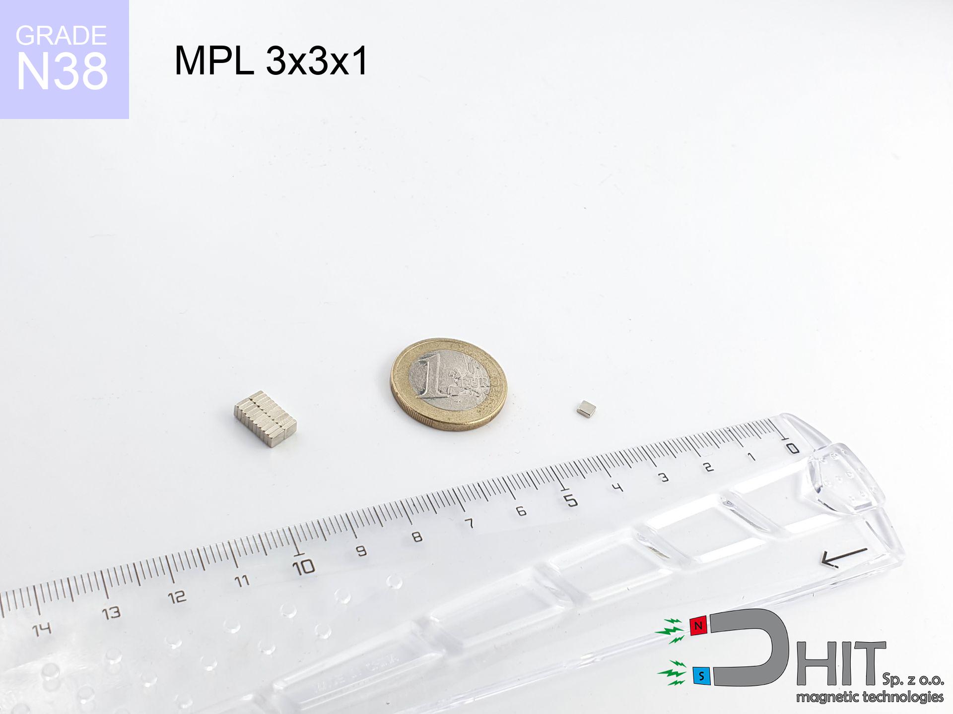
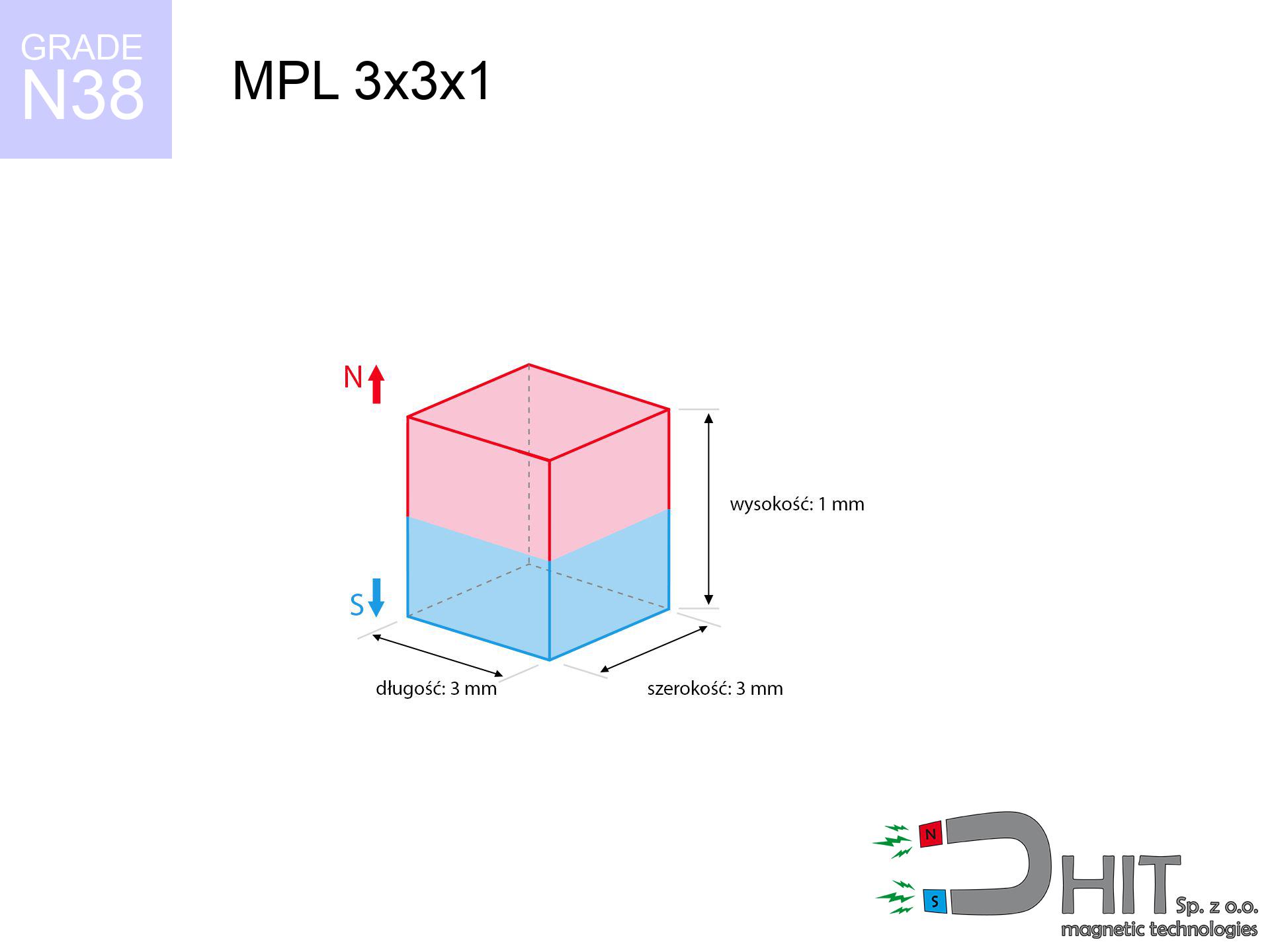
MPL 3x3x1 / N38 - lamellar magnet
lamellar magnet
Catalog no 020146
GTIN/EAN: 5906301811527
length
3 mm [±0,1 mm]
Width
3 mm [±0,1 mm]
Height
1 mm [±0,1 mm]
Weight
0.07 g
Magnetization Direction
↑ axial
Load capacity
0.23 kg / 2.29 N
Magnetic Induction
317.31 mT / 3173 Gs
Coating
[NiCuNi] Nickel
0.1845 ZŁ with VAT / pcs + price for transport
0.1500 ZŁ net + 23% VAT / pcs
bulk discounts:
Need more?
Contact us by phone
+48 22 499 98 98
if you prefer get in touch via
contact form
the contact page.
Lifting power as well as shape of magnets can be checked with our
our magnetic calculator.
Same-day shipping for orders placed before 14:00.
Detailed specification - MPL 3x3x1 / N38 - lamellar magnet
Specification / characteristics - MPL 3x3x1 / N38 - lamellar magnet
| properties | values |
|---|---|
| Cat. no. | 020146 |
| GTIN/EAN | 5906301811527 |
| Production/Distribution | Dhit sp. z o.o. |
| Country of origin | Poland / China / Germany |
| Customs code | 85059029 |
| length | 3 mm [±0,1 mm] |
| Width | 3 mm [±0,1 mm] |
| Height | 1 mm [±0,1 mm] |
| Weight | 0.07 g |
| Magnetization Direction | ↑ axial |
| Load capacity ~ ? | 0.23 kg / 2.29 N |
| Magnetic Induction ~ ? | 317.31 mT / 3173 Gs |
| Coating | [NiCuNi] Nickel |
| Manufacturing Tolerance | ±0.1 mm |
Magnetic properties of material N38
| properties | values | units |
|---|---|---|
| remenance Br [min. - max.] ? | 12.2-12.6 | kGs |
| remenance Br [min. - max.] ? | 1220-1260 | mT |
| coercivity bHc ? | 10.8-11.5 | kOe |
| coercivity bHc ? | 860-915 | kA/m |
| actual internal force iHc | ≥ 12 | kOe |
| actual internal force iHc | ≥ 955 | kA/m |
| energy density [min. - max.] ? | 36-38 | BH max MGOe |
| energy density [min. - max.] ? | 287-303 | BH max KJ/m |
| max. temperature ? | ≤ 80 | °C |
Physical properties of sintered neodymium magnets Nd2Fe14B at 20°C
| properties | values | units |
|---|---|---|
| Vickers hardness | ≥550 | Hv |
| Density | ≥7.4 | g/cm3 |
| Curie Temperature TC | 312 - 380 | °C |
| Curie Temperature TF | 593 - 716 | °F |
| Specific resistance | 150 | μΩ⋅cm |
| Bending strength | 250 | MPa |
| Compressive strength | 1000~1100 | MPa |
| Thermal expansion parallel (∥) to orientation (M) | (3-4) x 10-6 | °C-1 |
| Thermal expansion perpendicular (⊥) to orientation (M) | -(1-3) x 10-6 | °C-1 |
| Young's modulus | 1.7 x 10⁴ | kg/mm² |
Physical simulation of the assembly - report
Presented data are the direct effect of a physical calculation. Values were calculated on models for the material Nd2Fe14B. Actual parameters might slightly differ from theoretical values. Please consider these data as a preliminary roadmap for designers.
Table 1: Static pull force (force vs distance) - characteristics
MPL 3x3x1 / N38
| Distance (mm) | Induction (Gauss) / mT | Pull Force (kg/lbs/g/N) | Risk Status |
|---|---|---|---|
| 0 mm |
3168 Gs
316.8 mT
|
0.23 kg / 0.51 lbs
230.0 g / 2.3 N
|
safe |
| 1 mm |
1565 Gs
156.5 mT
|
0.06 kg / 0.12 lbs
56.1 g / 0.6 N
|
safe |
| 2 mm |
659 Gs
65.9 mT
|
0.01 kg / 0.02 lbs
9.9 g / 0.1 N
|
safe |
| 3 mm |
307 Gs
30.7 mT
|
0.00 kg / 0.00 lbs
2.2 g / 0.0 N
|
safe |
| 5 mm |
94 Gs
9.4 mT
|
0.00 kg / 0.00 lbs
0.2 g / 0.0 N
|
safe |
| 10 mm |
15 Gs
1.5 mT
|
0.00 kg / 0.00 lbs
0.0 g / 0.0 N
|
safe |
| 15 mm |
5 Gs
0.5 mT
|
0.00 kg / 0.00 lbs
0.0 g / 0.0 N
|
safe |
| 20 mm |
2 Gs
0.2 mT
|
0.00 kg / 0.00 lbs
0.0 g / 0.0 N
|
safe |
| 30 mm |
1 Gs
0.1 mT
|
0.00 kg / 0.00 lbs
0.0 g / 0.0 N
|
safe |
| 50 mm |
0 Gs
0.0 mT
|
0.00 kg / 0.00 lbs
0.0 g / 0.0 N
|
safe |
Table 2: Slippage force (wall)
MPL 3x3x1 / N38
| Distance (mm) | Friction coefficient | Pull Force (kg/lbs/g/N) |
|---|---|---|
| 0 mm | Stal (~0.2) |
0.05 kg / 0.10 lbs
46.0 g / 0.5 N
|
| 1 mm | Stal (~0.2) |
0.01 kg / 0.03 lbs
12.0 g / 0.1 N
|
| 2 mm | Stal (~0.2) |
0.00 kg / 0.00 lbs
2.0 g / 0.0 N
|
| 3 mm | Stal (~0.2) |
0.00 kg / 0.00 lbs
0.0 g / 0.0 N
|
| 5 mm | Stal (~0.2) |
0.00 kg / 0.00 lbs
0.0 g / 0.0 N
|
| 10 mm | Stal (~0.2) |
0.00 kg / 0.00 lbs
0.0 g / 0.0 N
|
| 15 mm | Stal (~0.2) |
0.00 kg / 0.00 lbs
0.0 g / 0.0 N
|
| 20 mm | Stal (~0.2) |
0.00 kg / 0.00 lbs
0.0 g / 0.0 N
|
| 30 mm | Stal (~0.2) |
0.00 kg / 0.00 lbs
0.0 g / 0.0 N
|
| 50 mm | Stal (~0.2) |
0.00 kg / 0.00 lbs
0.0 g / 0.0 N
|
Table 3: Vertical assembly (shearing) - behavior on slippery surfaces
MPL 3x3x1 / N38
| Surface type | Friction coefficient / % Mocy | Max load (kg/lbs/g/N) |
|---|---|---|
| Raw steel |
µ = 0.3
30% Nominalnej Siły
|
0.07 kg / 0.15 lbs
69.0 g / 0.7 N
|
| Painted steel (standard) |
µ = 0.2
20% Nominalnej Siły
|
0.05 kg / 0.10 lbs
46.0 g / 0.5 N
|
| Oily/slippery steel |
µ = 0.1
10% Nominalnej Siły
|
0.02 kg / 0.05 lbs
23.0 g / 0.2 N
|
| Magnet with anti-slip rubber |
µ = 0.5
50% Nominalnej Siły
|
0.12 kg / 0.25 lbs
115.0 g / 1.1 N
|
Table 4: Steel thickness (substrate influence) - power losses
MPL 3x3x1 / N38
| Steel thickness (mm) | % power | Real pull force (kg/lbs/g/N) |
|---|---|---|
| 0.5 mm |
|
0.02 kg / 0.05 lbs
23.0 g / 0.2 N
|
| 1 mm |
|
0.06 kg / 0.13 lbs
57.5 g / 0.6 N
|
| 2 mm |
|
0.12 kg / 0.25 lbs
115.0 g / 1.1 N
|
| 3 mm |
|
0.17 kg / 0.38 lbs
172.5 g / 1.7 N
|
| 5 mm |
|
0.23 kg / 0.51 lbs
230.0 g / 2.3 N
|
| 10 mm |
|
0.23 kg / 0.51 lbs
230.0 g / 2.3 N
|
| 11 mm |
|
0.23 kg / 0.51 lbs
230.0 g / 2.3 N
|
| 12 mm |
|
0.23 kg / 0.51 lbs
230.0 g / 2.3 N
|
Table 5: Thermal stability (material behavior) - resistance threshold
MPL 3x3x1 / N38
| Ambient temp. (°C) | Power loss | Remaining pull (kg/lbs/g/N) | Status |
|---|---|---|---|
| 20 °C | 0.0% |
0.23 kg / 0.51 lbs
230.0 g / 2.3 N
|
OK |
| 40 °C | -2.2% |
0.22 kg / 0.50 lbs
224.9 g / 2.2 N
|
OK |
| 60 °C | -4.4% |
0.22 kg / 0.48 lbs
219.9 g / 2.2 N
|
|
| 80 °C | -6.6% |
0.21 kg / 0.47 lbs
214.8 g / 2.1 N
|
|
| 100 °C | -28.8% |
0.16 kg / 0.36 lbs
163.8 g / 1.6 N
|
Table 6: Magnet-Magnet interaction (attraction) - forces in the system
MPL 3x3x1 / N38
| Gap (mm) | Attraction (kg/lbs) (N-S) | Sliding Force (kg/lbs/g/N) | Repulsion (kg/lbs) (N-N) |
|---|---|---|---|
| 0 mm |
0.56 kg / 1.23 lbs
4 719 Gs
|
0.08 kg / 0.18 lbs
84 g / 0.8 N
|
N/A |
| 1 mm |
0.31 kg / 0.68 lbs
4 706 Gs
|
0.05 kg / 0.10 lbs
46 g / 0.5 N
|
0.28 kg / 0.61 lbs
~0 Gs
|
| 2 mm |
0.14 kg / 0.30 lbs
3 129 Gs
|
0.02 kg / 0.04 lbs
20 g / 0.2 N
|
0.12 kg / 0.27 lbs
~0 Gs
|
| 3 mm |
0.06 kg / 0.12 lbs
2 019 Gs
|
0.01 kg / 0.02 lbs
8 g / 0.1 N
|
0.05 kg / 0.11 lbs
~0 Gs
|
| 5 mm |
0.01 kg / 0.02 lbs
885 Gs
|
0.00 kg / 0.00 lbs
2 g / 0.0 N
|
0.01 kg / 0.02 lbs
~0 Gs
|
| 10 mm |
0.00 kg / 0.00 lbs
188 Gs
|
0.00 kg / 0.00 lbs
0 g / 0.0 N
|
0.00 kg / 0.00 lbs
~0 Gs
|
| 20 mm |
0.00 kg / 0.00 lbs
30 Gs
|
0.00 kg / 0.00 lbs
0 g / 0.0 N
|
0.00 kg / 0.00 lbs
~0 Gs
|
| 50 mm |
0.00 kg / 0.00 lbs
2 Gs
|
0.00 kg / 0.00 lbs
0 g / 0.0 N
|
0.00 kg / 0.00 lbs
~0 Gs
|
| 60 mm |
0.00 kg / 0.00 lbs
1 Gs
|
0.00 kg / 0.00 lbs
0 g / 0.0 N
|
0.00 kg / 0.00 lbs
~0 Gs
|
| 70 mm |
0.00 kg / 0.00 lbs
1 Gs
|
0.00 kg / 0.00 lbs
0 g / 0.0 N
|
0.00 kg / 0.00 lbs
~0 Gs
|
| 80 mm |
0.00 kg / 0.00 lbs
1 Gs
|
0.00 kg / 0.00 lbs
0 g / 0.0 N
|
0.00 kg / 0.00 lbs
~0 Gs
|
| 90 mm |
0.00 kg / 0.00 lbs
0 Gs
|
0.00 kg / 0.00 lbs
0 g / 0.0 N
|
0.00 kg / 0.00 lbs
~0 Gs
|
| 100 mm |
0.00 kg / 0.00 lbs
0 Gs
|
0.00 kg / 0.00 lbs
0 g / 0.0 N
|
0.00 kg / 0.00 lbs
~0 Gs
|
Table 7: Hazards (electronics) - warnings
MPL 3x3x1 / N38
| Object / Device | Limit (Gauss) / mT | Safe distance |
|---|---|---|
| Pacemaker | 5 Gs (0.5 mT) | 1.5 cm |
| Hearing aid | 10 Gs (1.0 mT) | 1.5 cm |
| Timepiece | 20 Gs (2.0 mT) | 1.0 cm |
| Phone / Smartphone | 40 Gs (4.0 mT) | 1.0 cm |
| Remote | 50 Gs (5.0 mT) | 1.0 cm |
| Payment card | 400 Gs (40.0 mT) | 0.5 cm |
| HDD hard drive | 600 Gs (60.0 mT) | 0.5 cm |
Table 8: Dynamics (cracking risk) - warning
MPL 3x3x1 / N38
| Start from (mm) | Speed (km/h) | Energy (J) | Predicted outcome |
|---|---|---|---|
| 10 mm |
57.81 km/h
(16.06 m/s)
|
0.01 J | |
| 30 mm |
100.13 km/h
(27.81 m/s)
|
0.03 J | |
| 50 mm |
129.27 km/h
(35.91 m/s)
|
0.05 J | |
| 100 mm |
182.81 km/h
(50.78 m/s)
|
0.09 J |
Table 9: Corrosion resistance
MPL 3x3x1 / N38
| Technical parameter | Value / Description |
|---|---|
| Coating type | [NiCuNi] Nickel |
| Layer structure | Nickel - Copper - Nickel |
| Layer thickness | 10-20 µm |
| Salt spray test (SST) ? | 24 h |
| Recommended environment | Indoors only (dry) |
Table 10: Construction data (Pc)
MPL 3x3x1 / N38
| Parameter | Value | SI Unit / Description |
|---|---|---|
| Magnetic Flux | 306 Mx | 3.1 µWb |
| Pc Coefficient | 0.40 | Low (Flat) |
Table 11: Hydrostatics and buoyancy
MPL 3x3x1 / N38
| Environment | Effective steel pull | Effect |
|---|---|---|
| Air (land) | 0.23 kg | Standard |
| Water (riverbed) |
0.26 kg
(+0.03 kg buoyancy gain)
|
+14.5% |
1. Vertical hold
*Warning: On a vertical wall, the magnet holds just ~20% of its max power.
2. Plate thickness effect
*Thin steel (e.g. 0.5mm PC case) drastically limits the holding force.
3. Thermal stability
*For N38 grade, the critical limit is 80°C.
4. Demagnetization curve and operating point (B-H)
chart generated for the permeance coefficient Pc (Permeance Coefficient) = 0.40
This simulation demonstrates the magnetic stability of the selected magnet under specific geometric conditions. The solid red line represents the demagnetization curve (material potential), while the dashed blue line is the load line based on the magnet's geometry. The Pc (Permeance Coefficient), also known as the load line slope, is a dimensionless value that describes the relationship between the magnet's shape and its magnetic stability. The intersection of these two lines (the black dot) is the operating point — it determines the actual magnetic flux density generated by the magnet in this specific configuration. A higher Pc value means the magnet is more 'slender' (tall relative to its area), resulting in a higher operating point and better resistance to irreversible demagnetization caused by external fields or temperature. A value of 0.42 is relatively low (typical for flat magnets), meaning the operating point is closer to the 'knee' of the curve — caution is advised when operating at temperatures near the maximum limit to avoid strength loss.
Chemical composition
| iron (Fe) | 64% – 68% |
| neodymium (Nd) | 29% – 32% |
| boron (B) | 1.1% – 1.2% |
| dysprosium (Dy) | 0.5% – 2.0% |
| coating (Ni-Cu-Ni) | < 0.05% |
Ecology and recycling (GPSR)
| recyclability (EoL) | 100% |
| recycled raw materials | ~10% (pre-cons) |
| carbon footprint | low / zredukowany |
| waste code (EWC) | 16 02 16 |
Other proposals


![SM 25x200 [2xM8] / N52 - magnetic separator](https://cdn3.dhit.pl/graphics/products/sm-25x200-2xm8-jas.jpg "SM 25x200 [2xM8] / N52 - magnetic separator")

Strengths as well as weaknesses of neodymium magnets.
Advantages
- They retain magnetic properties for nearly ten years – the drop is just ~1% (according to analyses),
- Neodymium magnets are distinguished by exceptionally resistant to magnetic field loss caused by external magnetic fields,
- The use of an refined coating of noble metals (nickel, gold, silver) causes the element to look better,
- They feature high magnetic induction at the operating surface, which improves attraction properties,
- Thanks to resistance to high temperature, they are capable of working (depending on the shape) even at temperatures up to 230°C and higher...
- Possibility of custom machining and optimizing to complex requirements,
- Wide application in innovative solutions – they are used in computer drives, electromotive mechanisms, medical devices, and complex engineering applications.
- Relatively small size with high pulling force – neodymium magnets offer high power in tiny dimensions, which enables their usage in small systems
Cons
- At strong impacts they can crack, therefore we advise placing them in steel cases. A metal housing provides additional protection against damage and increases the magnet's durability.
- Neodymium magnets demagnetize when exposed to high temperatures. After reaching 80°C, many of them experience permanent drop of power (a factor is the shape as well as dimensions of the magnet). We offer magnets specially adapted to work at temperatures up to 230°C marked [AH], which are extremely resistant to heat
- They rust in a humid environment - during use outdoors we recommend using waterproof magnets e.g. in rubber, plastic
- We recommend cover - magnetic mount, due to difficulties in producing nuts inside the magnet and complex shapes.
- Health risk related to microscopic parts of magnets pose a threat, if swallowed, which is particularly important in the context of child safety. Furthermore, tiny parts of these products can disrupt the diagnostic process medical in case of swallowing.
- Higher cost of purchase is one of the disadvantages compared to ceramic magnets, especially in budget applications
Pull force analysis
Optimal lifting capacity of a neodymium magnet – what it depends on?
- with the contact of a yoke made of low-carbon steel, guaranteeing full magnetic saturation
- with a thickness of at least 10 mm
- with a surface cleaned and smooth
- without any clearance between the magnet and steel
- for force applied at a right angle (in the magnet axis)
- in neutral thermal conditions
Determinants of practical lifting force of a magnet
- Clearance – the presence of any layer (rust, tape, gap) interrupts the magnetic circuit, which lowers capacity steeply (even by 50% at 0.5 mm).
- Load vector – maximum parameter is reached only during pulling at a 90° angle. The force required to slide of the magnet along the plate is typically several times smaller (approx. 1/5 of the lifting capacity).
- Metal thickness – thin material does not allow full use of the magnet. Part of the magnetic field passes through the material instead of generating force.
- Plate material – low-carbon steel attracts best. Higher carbon content lower magnetic permeability and lifting capacity.
- Base smoothness – the smoother and more polished the plate, the better the adhesion and stronger the hold. Roughness creates an air distance.
- Heat – neodymium magnets have a sensitivity to temperature. When it is hot they are weaker, and in frost they can be stronger (up to a certain limit).
Lifting capacity testing was performed on plates with a smooth surface of suitable thickness, under a perpendicular pulling force, however under attempts to slide the magnet the holding force is lower. Moreover, even a minimal clearance between the magnet and the plate reduces the lifting capacity.
Safe handling of neodymium magnets
Health Danger
People with a ICD must keep an safe separation from magnets. The magnetic field can interfere with the operation of the implant.
Do not overheat magnets
Regular neodymium magnets (grade N) lose power when the temperature goes above 80°C. Damage is permanent.
Adults only
Absolutely store magnets away from children. Choking hazard is high, and the effects of magnets connecting inside the body are life-threatening.
Crushing risk
Large magnets can break fingers in a fraction of a second. Under no circumstances place your hand betwixt two attracting surfaces.
Magnetic interference
A strong magnetic field disrupts the operation of magnetometers in phones and GPS navigation. Do not bring magnets close to a smartphone to prevent breaking the sensors.
Handling rules
Exercise caution. Neodymium magnets attract from a distance and snap with massive power, often faster than you can react.
Safe distance
Device Safety: Strong magnets can ruin data carriers and delicate electronics (heart implants, medical aids, mechanical watches).
Warning for allergy sufferers
Medical facts indicate that nickel (the usual finish) is a potent allergen. If you have an allergy, refrain from direct skin contact or select coated magnets.
Magnets are brittle
Beware of splinters. Magnets can explode upon violent connection, ejecting sharp fragments into the air. We recommend safety glasses.
Fire risk
Machining of neodymium magnets poses a fire risk. Neodymium dust reacts violently with oxygen and is hard to extinguish.
Tabela kosztu i czasu dostawy
Płatność przed wysyłką:

GLS kurier
Przesyłka będzie u Ciebie za 2-3 dni
14.99 ZŁ

InPost Paczkomaty 24/7
Przesyłka będzie u Ciebie za 1-2 dni
12.30 ZŁ
Płatność przy odbiorze (pobranie):
GLS kurier
Przesyłka będzie u Ciebie za 1-2 dni
23.00 ZŁ
Rate the product
Your rating