

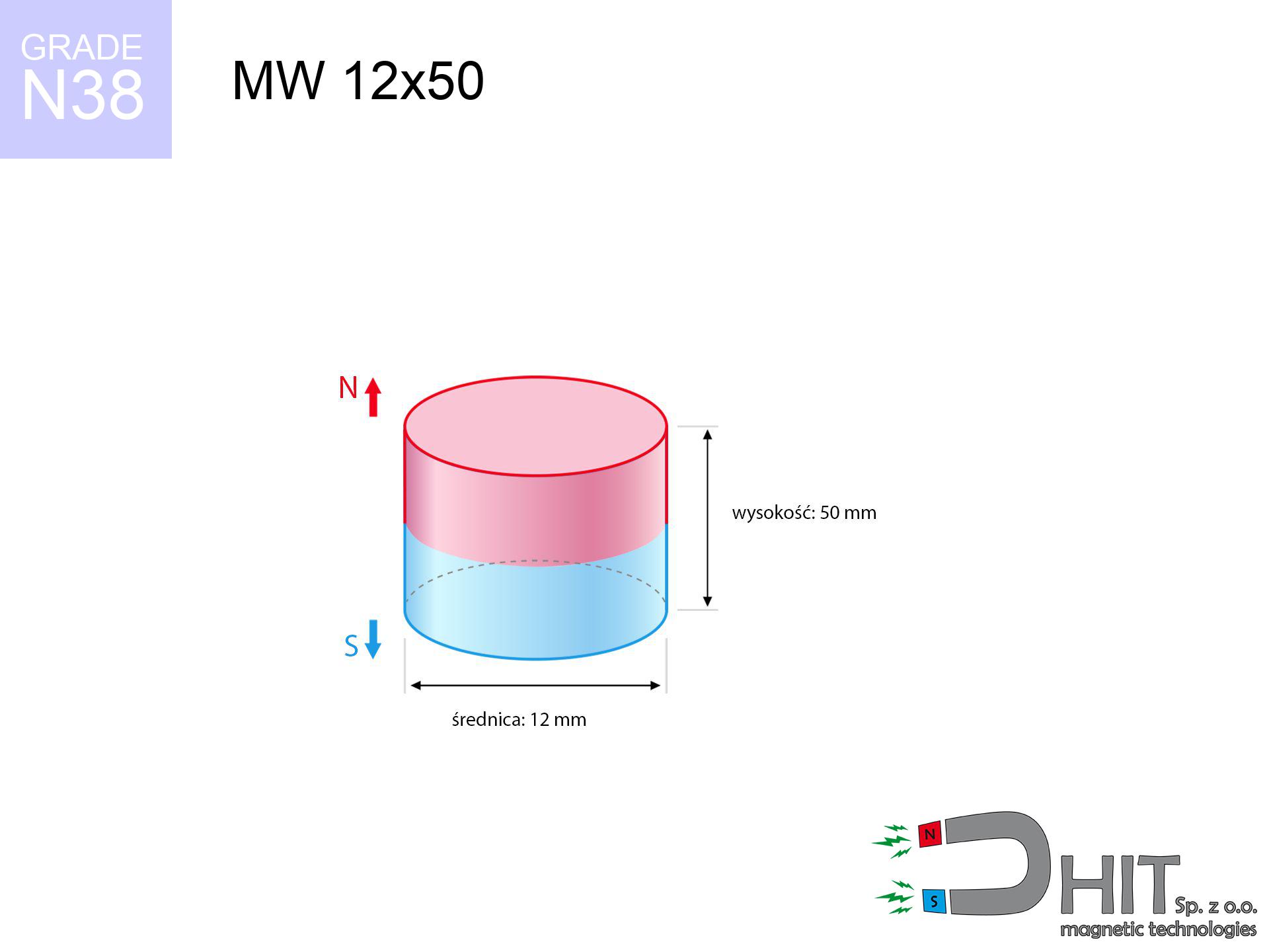
MW 12x50 / N38 - cylindrical magnet
cylindrical magnet
Catalog no 010020
GTIN/EAN: 5906301810193
Diameter Ø
12 mm [±0,1 mm]
Height
50 mm [±0,1 mm]
Weight
42.41 g
Magnetization Direction
↑ axial
Load capacity
2.62 kg / 25.73 N
Magnetic Induction
614.94 mT / 6149 Gs
Coating
[NiCuNi] Nickel
28.29 ZŁ with VAT / pcs + price for transport
23.00 ZŁ net + 23% VAT / pcs
bulk discounts:
Need more?Engineering report for this magnet
Full PDF analysis: pull and shear force, effect of distance, temperature and plate thickness, safety distances and the demagnetization curve.
Call us now
+48 888 99 98 98
alternatively get in touch by means of
request form
through our site.
Force along with appearance of magnetic components can be reviewed on our
our magnetic calculator.
Orders placed before 14:00 will be shipped the same business day.
Detailed specification - MW 12x50 / N38 - cylindrical magnet
Specification / characteristics - MW 12x50 / N38 - cylindrical magnet
| properties | values |
|---|---|
| Cat. no. | 010020 |
| GTIN/EAN | 5906301810193 |
| Production/Distribution | Dhit sp. z o.o. |
| Country of origin | Poland / China / Germany |
| Customs code | 85059029 |
| Diameter Ø | 12 mm [±0,1 mm] |
| Height | 50 mm [±0,1 mm] |
| Weight | 42.41 g |
| Magnetization Direction | ↑ axial |
| Load capacity ~ ? | 2.62 kg / 25.73 N |
| Magnetic Induction ~ ? | 614.94 mT / 6149 Gs |
| Coating | [NiCuNi] Nickel |
| Manufacturing Tolerance | ±0.1 mm |
Magnetic properties of material N38
| properties | values | units |
|---|---|---|
| remenance Br [min. - max.] ? | 12.2-12.6 | kGs |
| remenance Br [min. - max.] ? | 1220-1260 | mT |
| coercivity bHc ? | 10.8-11.5 | kOe |
| coercivity bHc ? | 860-915 | kA/m |
| actual internal force iHc | ≥ 12 | kOe |
| actual internal force iHc | ≥ 955 | kA/m |
| energy density [min. - max.] ? | 36-38 | BH max MGOe |
| energy density [min. - max.] ? | 287-303 | BH max KJ/m |
| max. temperature ? | ≤ 80 | °C |
Physical properties of sintered neodymium magnets Nd2Fe14B at 20°C
| properties | values | units |
|---|---|---|
| Vickers hardness | ≥550 | Hv |
| Density | ≥7.4 | g/cm3 |
| Curie Temperature TC | 312 - 380 | °C |
| Curie Temperature TF | 593 - 716 | °F |
| Specific resistance | 150 | μΩ⋅cm |
| Bending strength | 250 | MPa |
| Compressive strength | 1000~1100 | MPa |
| Thermal expansion parallel (∥) to orientation (M) | (3-4) x 10-6 | °C-1 |
| Thermal expansion perpendicular (⊥) to orientation (M) | -(1-3) x 10-6 | °C-1 |
| Young's modulus | 1.7 x 10⁴ | kg/mm² |
Engineering analysis of the magnet - technical parameters
These data are the result of a physical analysis. Results were calculated on models for the class Nd2Fe14B. Actual performance may deviate from the simulation results. Please consider these data as a supplementary guide when designing systems.
Table 1: Static force (force vs distance) - characteristics
MW 12x50 / N38
| Distance (mm) | Induction (Gauss) / mT | Pull Force (kg/lbs/g/N) | Risk Status |
|---|---|---|---|
| 0 mm |
6146 Gs
614.6 mT
|
2.62 kg / 5.78 lbs
2620.0 g / 25.7 N
|
medium risk |
| 1 mm |
5138 Gs
513.8 mT
|
1.83 kg / 4.04 lbs
1831.5 g / 18.0 N
|
weak grip |
| 2 mm |
4199 Gs
419.9 mT
|
1.22 kg / 2.70 lbs
1222.9 g / 12.0 N
|
weak grip |
| 3 mm |
3388 Gs
338.8 mT
|
0.80 kg / 1.76 lbs
796.3 g / 7.8 N
|
weak grip |
| 5 mm |
2194 Gs
219.4 mT
|
0.33 kg / 0.74 lbs
334.0 g / 3.3 N
|
weak grip |
| 10 mm |
853 Gs
85.3 mT
|
0.05 kg / 0.11 lbs
50.4 g / 0.5 N
|
weak grip |
| 15 mm |
417 Gs
41.7 mT
|
0.01 kg / 0.03 lbs
12.1 g / 0.1 N
|
weak grip |
| 20 mm |
239 Gs
23.9 mT
|
0.00 kg / 0.01 lbs
4.0 g / 0.0 N
|
weak grip |
| 30 mm |
103 Gs
10.3 mT
|
0.00 kg / 0.00 lbs
0.7 g / 0.0 N
|
weak grip |
| 50 mm |
33 Gs
3.3 mT
|
0.00 kg / 0.00 lbs
0.1 g / 0.0 N
|
weak grip |
Table 2: Shear load (vertical surface)
MW 12x50 / N38
| Distance (mm) | Friction coefficient | Pull Force (kg/lbs/g/N) |
|---|---|---|
| 0 mm | Stal (~0.2) |
0.52 kg / 1.16 lbs
524.0 g / 5.1 N
|
| 1 mm | Stal (~0.2) |
0.37 kg / 0.81 lbs
366.0 g / 3.6 N
|
| 2 mm | Stal (~0.2) |
0.24 kg / 0.54 lbs
244.0 g / 2.4 N
|
| 3 mm | Stal (~0.2) |
0.16 kg / 0.35 lbs
160.0 g / 1.6 N
|
| 5 mm | Stal (~0.2) |
0.07 kg / 0.15 lbs
66.0 g / 0.6 N
|
| 10 mm | Stal (~0.2) |
0.01 kg / 0.02 lbs
10.0 g / 0.1 N
|
| 15 mm | Stal (~0.2) |
0.00 kg / 0.00 lbs
2.0 g / 0.0 N
|
| 20 mm | Stal (~0.2) |
0.00 kg / 0.00 lbs
0.0 g / 0.0 N
|
| 30 mm | Stal (~0.2) |
0.00 kg / 0.00 lbs
0.0 g / 0.0 N
|
| 50 mm | Stal (~0.2) |
0.00 kg / 0.00 lbs
0.0 g / 0.0 N
|
Table 3: Vertical assembly (shearing) - behavior on slippery surfaces
MW 12x50 / N38
| Surface type | Friction coefficient / % Mocy | Max load (kg/lbs/g/N) |
|---|---|---|
| Raw steel |
µ = 0.3
30% Nominalnej Siły
|
0.79 kg / 1.73 lbs
786.0 g / 7.7 N
|
| Painted steel (standard) |
µ = 0.2
20% Nominalnej Siły
|
0.52 kg / 1.16 lbs
524.0 g / 5.1 N
|
| Oily/slippery steel |
µ = 0.1
10% Nominalnej Siły
|
0.26 kg / 0.58 lbs
262.0 g / 2.6 N
|
| Magnet with anti-slip rubber |
µ = 0.5
50% Nominalnej Siły
|
1.31 kg / 2.89 lbs
1310.0 g / 12.9 N
|
Table 4: Material efficiency (saturation) - power losses
MW 12x50 / N38
| Steel thickness (mm) | % power | Real pull force (kg/lbs/g/N) |
|---|---|---|
| 0.5 mm |
|
0.26 kg / 0.58 lbs
262.0 g / 2.6 N
|
| 1 mm |
|
0.66 kg / 1.44 lbs
655.0 g / 6.4 N
|
| 2 mm |
|
1.31 kg / 2.89 lbs
1310.0 g / 12.9 N
|
| 3 mm |
|
1.97 kg / 4.33 lbs
1965.0 g / 19.3 N
|
| 5 mm |
|
2.62 kg / 5.78 lbs
2620.0 g / 25.7 N
|
| 10 mm |
|
2.62 kg / 5.78 lbs
2620.0 g / 25.7 N
|
| 11 mm |
|
2.62 kg / 5.78 lbs
2620.0 g / 25.7 N
|
| 12 mm |
|
2.62 kg / 5.78 lbs
2620.0 g / 25.7 N
|
Table 5: Thermal resistance (material behavior) - power drop
MW 12x50 / N38
| Ambient temp. (°C) | Power loss | Remaining pull (kg/lbs/g/N) | Status |
|---|---|---|---|
| 20 °C | 0.0% |
2.62 kg / 5.78 lbs
2620.0 g / 25.7 N
|
OK |
| 40 °C | -2.2% |
2.56 kg / 5.65 lbs
2562.4 g / 25.1 N
|
OK |
| 60 °C | -4.4% |
2.50 kg / 5.52 lbs
2504.7 g / 24.6 N
|
OK |
| 80 °C | -6.6% |
2.45 kg / 5.39 lbs
2447.1 g / 24.0 N
|
|
| 100 °C | -28.8% |
1.87 kg / 4.11 lbs
1865.4 g / 18.3 N
|
Table 6: Two magnets (attraction) - field collision
MW 12x50 / N38
| Gap (mm) | Attraction (kg/lbs) (N-S) | Sliding Force (kg/lbs/g/N) | Repulsion (kg/lbs) (N-N) |
|---|---|---|---|
| 0 mm |
26.33 kg / 58.05 lbs
6 179 Gs
|
3.95 kg / 8.71 lbs
3950 g / 38.7 N
|
N/A |
| 1 mm |
22.19 kg / 48.93 lbs
11 284 Gs
|
3.33 kg / 7.34 lbs
3329 g / 32.7 N
|
19.97 kg / 44.04 lbs
~0 Gs
|
| 2 mm |
18.41 kg / 40.58 lbs
10 277 Gs
|
2.76 kg / 6.09 lbs
2761 g / 27.1 N
|
16.57 kg / 36.53 lbs
~0 Gs
|
| 3 mm |
15.11 kg / 33.30 lbs
9 309 Gs
|
2.27 kg / 5.00 lbs
2266 g / 22.2 N
|
13.60 kg / 29.97 lbs
~0 Gs
|
| 5 mm |
9.94 kg / 21.91 lbs
7 551 Gs
|
1.49 kg / 3.29 lbs
1491 g / 14.6 N
|
8.94 kg / 19.72 lbs
~0 Gs
|
| 10 mm |
3.36 kg / 7.40 lbs
4 389 Gs
|
0.50 kg / 1.11 lbs
504 g / 4.9 N
|
3.02 kg / 6.66 lbs
~0 Gs
|
| 20 mm |
0.51 kg / 1.12 lbs
1 706 Gs
|
0.08 kg / 0.17 lbs
76 g / 0.7 N
|
0.46 kg / 1.01 lbs
~0 Gs
|
| 50 mm |
0.02 kg / 0.04 lbs
303 Gs
|
0.00 kg / 0.01 lbs
2 g / 0.0 N
|
0.01 kg / 0.03 lbs
~0 Gs
|
| 60 mm |
0.01 kg / 0.02 lbs
206 Gs
|
0.00 kg / 0.00 lbs
1 g / 0.0 N
|
0.00 kg / 0.00 lbs
~0 Gs
|
| 70 mm |
0.00 kg / 0.01 lbs
148 Gs
|
0.00 kg / 0.00 lbs
1 g / 0.0 N
|
0.00 kg / 0.00 lbs
~0 Gs
|
| 80 mm |
0.00 kg / 0.00 lbs
110 Gs
|
0.00 kg / 0.00 lbs
0 g / 0.0 N
|
0.00 kg / 0.00 lbs
~0 Gs
|
| 90 mm |
0.00 kg / 0.00 lbs
84 Gs
|
0.00 kg / 0.00 lbs
0 g / 0.0 N
|
0.00 kg / 0.00 lbs
~0 Gs
|
| 100 mm |
0.00 kg / 0.00 lbs
66 Gs
|
0.00 kg / 0.00 lbs
0 g / 0.0 N
|
0.00 kg / 0.00 lbs
~0 Gs
|
Table 7: Safety (HSE) (electronics) - warnings
MW 12x50 / N38
| Object / Device | Limit (Gauss) / mT | Safe distance |
|---|---|---|
| Pacemaker | 5 Gs (0.5 mT) | 11.0 cm |
| Hearing aid | 10 Gs (1.0 mT) | 8.5 cm |
| Mechanical watch | 20 Gs (2.0 mT) | 6.5 cm |
| Phone / Smartphone | 40 Gs (4.0 mT) | 5.0 cm |
| Remote | 50 Gs (5.0 mT) | 4.5 cm |
| Payment card | 400 Gs (40.0 mT) | 2.0 cm |
| HDD hard drive | 600 Gs (60.0 mT) | 1.5 cm |
Table 8: Dynamics (kinetic energy) - collision effects
MW 12x50 / N38
| Start from (mm) | Speed (km/h) | Energy (J) | Predicted outcome |
|---|---|---|---|
| 10 mm |
8.02 km/h
(2.23 m/s)
|
0.11 J | |
| 30 mm |
13.73 km/h
(3.81 m/s)
|
0.31 J | |
| 50 mm |
17.73 km/h
(4.92 m/s)
|
0.51 J | |
| 100 mm |
25.07 km/h
(6.96 m/s)
|
1.03 J |
Table 9: Corrosion resistance
MW 12x50 / N38
| Technical parameter | Value / Description |
|---|---|
| Coating type | [NiCuNi] Nickel |
| Layer structure | Nickel - Copper - Nickel |
| Layer thickness | 10-20 µm |
| Salt spray test (SST) ? | 24 h |
| Recommended environment | Indoors only (dry) |
Table 10: Electrical data (Pc)
MW 12x50 / N38
| Parameter | Value | SI Unit / Description |
|---|---|---|
| Magnetic Flux | 8 230 Mx | 82.3 µWb |
| Pc Coefficient | 1.49 | High (Stable) |
Table 11: Hydrostatics and buoyancy
MW 12x50 / N38
| Environment | Effective steel pull | Effect |
|---|---|---|
| Air (land) | 2.62 kg | Standard |
| Water (riverbed) |
3.00 kg
(+0.38 kg buoyancy gain)
|
+14.5% |
1. Sliding resistance
*Warning: On a vertical wall, the magnet retains only ~20% of its nominal pull.
2. Efficiency vs thickness
*Thin metal sheet (e.g. 0.5mm PC case) severely weakens the holding force.
3. Temperature resistance
*For N38 material, the critical limit is 80°C.
4. Demagnetization curve and operating point (B-H)
chart generated for the permeance coefficient Pc (Permeance Coefficient) = 1.49
The chart above illustrates the magnetic characteristics of the material within the second quadrant of the hysteresis loop. The solid red line represents the demagnetization curve (material potential), while the dashed blue line is the load line based on the magnet's geometry. The Pc (Permeance Coefficient), also known as the load line slope, is a dimensionless value that describes the relationship between the magnet's shape and its magnetic stability. The intersection of these two lines (the black dot) is the operating point — it determines the actual magnetic flux density generated by the magnet in this specific configuration. A higher Pc value means the magnet is more 'slender' (tall relative to its area), resulting in a higher operating point and better resistance to irreversible demagnetization caused by external fields or temperature. A value of 0.42 is relatively low (typical for flat magnets), meaning the operating point is closer to the 'knee' of the curve — caution is advised when operating at temperatures near the maximum limit to avoid strength loss.
Chemical composition
| iron (Fe) | 64% – 68% |
| neodymium (Nd) | 29% – 32% |
| boron (B) | 1.1% – 1.2% |
| dysprosium (Dy) | 0.5% – 2.0% |
| coating (Ni-Cu-Ni) | < 0.05% |
Ecology and recycling (GPSR)
| recyclability (EoL) | 100% |
| recycled raw materials | ~10% (pre-cons) |
| carbon footprint | low / zredukowany |
| waste code (EWC) | 16 02 16 |
Other proposals


![UMH 60x15x69 [M8] / N38 - magnetic holder with hook](https://cdn3.dhit.pl/graphics/products/umh-60x15x69-m8-nij.jpg "UMH 60x15x69 [M8] / N38 - magnetic holder with hook")
Advantages as well as disadvantages of Nd2Fe14B magnets.
Advantages
- They have unchanged lifting capacity, and over more than ten years their performance decreases symbolically – ~1% (according to theory),
- They do not lose their magnetic properties even under external field action,
- Thanks to the shiny finish, the layer of nickel, gold-plated, or silver gives an elegant appearance,
- Magnetic induction on the working part of the magnet turns out to be strong,
- Made from properly selected components, these magnets show impressive resistance to high heat, enabling them to function (depending on their shape) at temperatures up to 230°C and above...
- In view of the option of accurate forming and adaptation to specialized projects, neodymium magnets can be created in a variety of forms and dimensions, which makes them more universal,
- Significant place in advanced technology sectors – they are commonly used in data components, electric drive systems, medical equipment, as well as complex engineering applications.
- Compactness – despite small sizes they offer powerful magnetic field, making them ideal for precision applications
Weaknesses
- To avoid cracks upon strong impacts, we suggest using special steel holders. Such a solution secures the magnet and simultaneously improves its durability.
- When exposed to high temperature, neodymium magnets suffer a drop in strength. Often, when the temperature exceeds 80°C, their strength decreases (depending on the size, as well as shape of the magnet). For those who need magnets for extreme conditions, we offer [AH] versions withstanding up to 230°C
- When exposed to humidity, magnets start to rust. To use them in conditions outside, it is recommended to use protective magnets, such as those in rubber or plastics, which secure oxidation and corrosion.
- Limited ability of producing threads in the magnet and complex shapes - preferred is cover - mounting mechanism.
- Possible danger to health – tiny shards of magnets are risky, if swallowed, which is particularly important in the context of child safety. Furthermore, small components of these devices can disrupt the diagnostic process medical in case of swallowing.
- Higher cost of purchase is one of the disadvantages compared to ceramic magnets, especially in budget applications
Holding force characteristics
Breakaway strength of the magnet in ideal conditions – what contributes to it?
- using a sheet made of mild steel, serving as a circuit closing element
- possessing a thickness of min. 10 mm to ensure full flux closure
- with a surface perfectly flat
- without the slightest insulating layer between the magnet and steel
- during pulling in a direction vertical to the plane
- at temperature approx. 20 degrees Celsius
Practical aspects of lifting capacity – factors
- Clearance – the presence of foreign body (paint, dirt, air) acts as an insulator, which lowers power steeply (even by 50% at 0.5 mm).
- Force direction – catalog parameter refers to detachment vertically. When attempting to slide, the magnet exhibits much less (typically approx. 20-30% of nominal force).
- Substrate thickness – to utilize 100% power, the steel must be adequately massive. Thin sheet limits the attraction force (the magnet "punches through" it).
- Material composition – not every steel attracts identically. Alloy additives weaken the interaction with the magnet.
- Surface structure – the smoother and more polished the plate, the better the adhesion and stronger the hold. Unevenness creates an air distance.
- Operating temperature – NdFeB sinters have a negative temperature coefficient. At higher temperatures they lose power, and in frost they can be stronger (up to a certain limit).
Holding force was checked on the plate surface of 20 mm thickness, when the force acted perpendicularly, whereas under attempts to slide the magnet the load capacity is reduced by as much as 5 times. Additionally, even a small distance between the magnet and the plate decreases the load capacity.
Safe handling of neodymium magnets
Heat sensitivity
Watch the temperature. Heating the magnet above 80 degrees Celsius will ruin its magnetic structure and strength.
Safe operation
Before use, check safety instructions. Sudden snapping can destroy the magnet or hurt your hand. Be predictive.
Nickel coating and allergies
Studies show that the nickel plating (standard magnet coating) is a common allergen. For allergy sufferers, refrain from direct skin contact and opt for coated magnets.
Pacemakers
People with a ICD must maintain an large gap from magnets. The magnetism can stop the functioning of the implant.
Cards and drives
Very strong magnetic fields can destroy records on payment cards, HDDs, and storage devices. Maintain a gap of at least 10 cm.
Compass and GPS
Be aware: neodymium magnets generate a field that interferes with precision electronics. Keep a separation from your phone, tablet, and GPS.
Product not for children
Only for adults. Small elements can be swallowed, causing intestinal necrosis. Keep out of reach of kids and pets.
Finger safety
Protect your hands. Two powerful magnets will join instantly with a force of several hundred kilograms, crushing everything in their path. Exercise extreme caution!
Protective goggles
Beware of splinters. Magnets can explode upon uncontrolled impact, ejecting shards into the air. Wear goggles.
Flammability
Powder created during grinding of magnets is self-igniting. Do not drill into magnets unless you are an expert.
Tabela kosztu i czasu dostawy
Płatność przed wysyłką:

GLS kurier
Przesyłka będzie u Ciebie za 2-3 dni
14.99 ZŁ

InPost Paczkomaty 24/7
Przesyłka będzie u Ciebie za 1-2 dni
12.30 ZŁ
Płatność przy odbiorze (pobranie):
GLS kurier
Przesyłka będzie u Ciebie za 1-2 dni
23.00 ZŁ
Rate the product
Your rating