
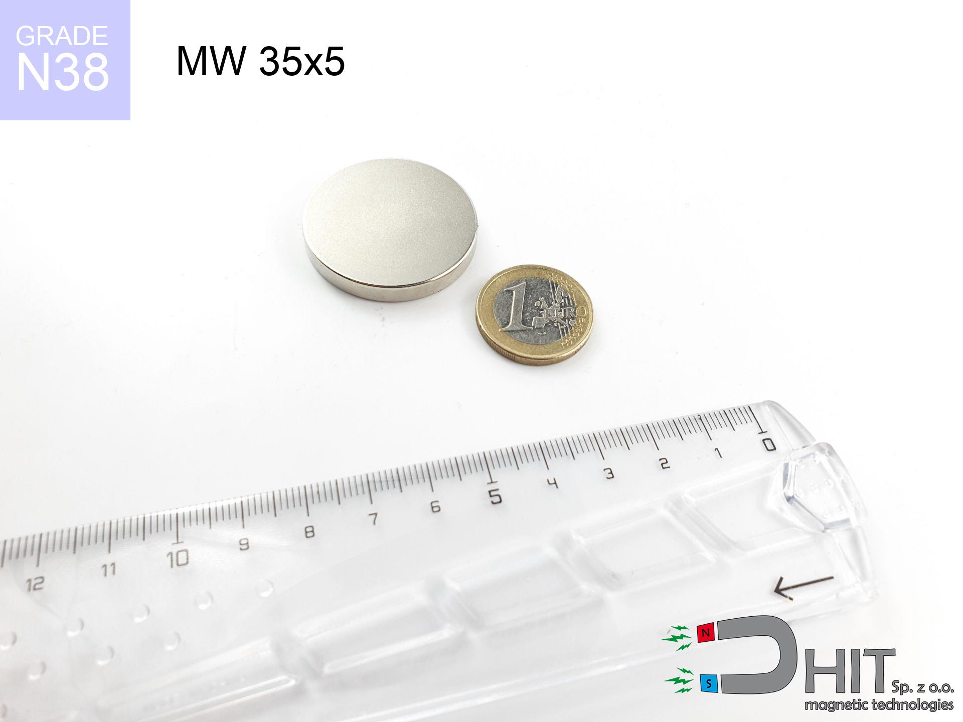
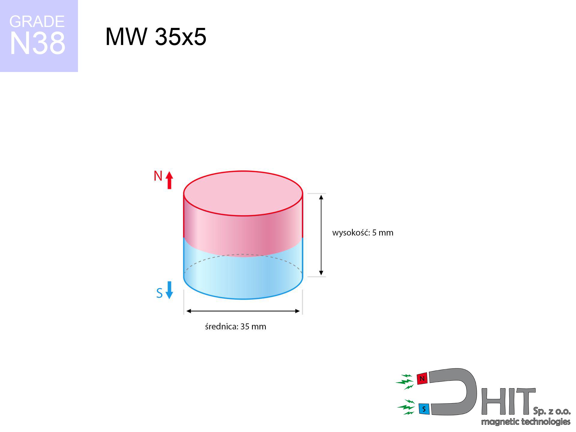
MW 35x5 / N38 - cylindrical magnet
cylindrical magnet
Catalog no 010059
GTIN/EAN: 5906301810582
Diameter Ø
35 mm [±0,1 mm]
Height
5 mm [±0,1 mm]
Weight
36.08 g
Magnetization Direction
↑ axial
Load capacity
9.25 kg / 90.73 N
Magnetic Induction
170.30 mT / 1703 Gs
Coating
[NiCuNi] Nickel
13.81 ZŁ with VAT / pcs + price for transport
11.23 ZŁ net + 23% VAT / pcs
bulk discounts:
Need more?
Give us a call
+48 22 499 98 98
otherwise drop us a message by means of
contact form
through our site.
Strength as well as shape of magnets can be verified using our
power calculator.
Orders submitted before 14:00 will be dispatched today!
Technical parameters - MW 35x5 / N38 - cylindrical magnet
Specification / characteristics - MW 35x5 / N38 - cylindrical magnet
| properties | values |
|---|---|
| Cat. no. | 010059 |
| GTIN/EAN | 5906301810582 |
| Production/Distribution | Dhit sp. z o.o. |
| Country of origin | Poland / China / Germany |
| Customs code | 85059029 |
| Diameter Ø | 35 mm [±0,1 mm] |
| Height | 5 mm [±0,1 mm] |
| Weight | 36.08 g |
| Magnetization Direction | ↑ axial |
| Load capacity ~ ? | 9.25 kg / 90.73 N |
| Magnetic Induction ~ ? | 170.30 mT / 1703 Gs |
| Coating | [NiCuNi] Nickel |
| Manufacturing Tolerance | ±0.1 mm |
Magnetic properties of material N38
| properties | values | units |
|---|---|---|
| remenance Br [min. - max.] ? | 12.2-12.6 | kGs |
| remenance Br [min. - max.] ? | 1220-1260 | mT |
| coercivity bHc ? | 10.8-11.5 | kOe |
| coercivity bHc ? | 860-915 | kA/m |
| actual internal force iHc | ≥ 12 | kOe |
| actual internal force iHc | ≥ 955 | kA/m |
| energy density [min. - max.] ? | 36-38 | BH max MGOe |
| energy density [min. - max.] ? | 287-303 | BH max KJ/m |
| max. temperature ? | ≤ 80 | °C |
Physical properties of sintered neodymium magnets Nd2Fe14B at 20°C
| properties | values | units |
|---|---|---|
| Vickers hardness | ≥550 | Hv |
| Density | ≥7.4 | g/cm3 |
| Curie Temperature TC | 312 - 380 | °C |
| Curie Temperature TF | 593 - 716 | °F |
| Specific resistance | 150 | μΩ⋅cm |
| Bending strength | 250 | MPa |
| Compressive strength | 1000~1100 | MPa |
| Thermal expansion parallel (∥) to orientation (M) | (3-4) x 10-6 | °C-1 |
| Thermal expansion perpendicular (⊥) to orientation (M) | -(1-3) x 10-6 | °C-1 |
| Young's modulus | 1.7 x 10⁴ | kg/mm² |
Physical modeling of the product - technical parameters
These data constitute the result of a physical analysis. Results were calculated on models for the material Nd2Fe14B. Real-world conditions might slightly differ. Treat these data as a preliminary roadmap when designing systems.
Table 1: Static pull force (force vs gap) - power drop
MW 35x5 / N38
| Distance (mm) | Induction (Gauss) / mT | Pull Force (kg/lbs/g/N) | Risk Status |
|---|---|---|---|
| 0 mm |
1703 Gs
170.3 mT
|
9.25 kg / 20.39 pounds
9250.0 g / 90.7 N
|
medium risk |
| 1 mm |
1657 Gs
165.7 mT
|
8.76 kg / 19.31 pounds
8759.4 g / 85.9 N
|
medium risk |
| 2 mm |
1599 Gs
159.9 mT
|
8.15 kg / 17.97 pounds
8152.2 g / 80.0 N
|
medium risk |
| 3 mm |
1530 Gs
153.0 mT
|
7.47 kg / 16.47 pounds
7468.5 g / 73.3 N
|
medium risk |
| 5 mm |
1373 Gs
137.3 mT
|
6.01 kg / 13.25 pounds
6011.5 g / 59.0 N
|
medium risk |
| 10 mm |
959 Gs
95.9 mT
|
2.93 kg / 6.47 pounds
2932.7 g / 28.8 N
|
medium risk |
| 15 mm |
631 Gs
63.1 mT
|
1.27 kg / 2.80 pounds
1270.4 g / 12.5 N
|
low risk |
| 20 mm |
413 Gs
41.3 mT
|
0.54 kg / 1.20 pounds
544.8 g / 5.3 N
|
low risk |
| 30 mm |
190 Gs
19.0 mT
|
0.12 kg / 0.25 pounds
115.2 g / 1.1 N
|
low risk |
| 50 mm |
56 Gs
5.6 mT
|
0.01 kg / 0.02 pounds
10.1 g / 0.1 N
|
low risk |
Table 2: Shear load (vertical surface)
MW 35x5 / N38
| Distance (mm) | Friction coefficient | Pull Force (kg/lbs/g/N) |
|---|---|---|
| 0 mm | Stal (~0.2) |
1.85 kg / 4.08 pounds
1850.0 g / 18.1 N
|
| 1 mm | Stal (~0.2) |
1.75 kg / 3.86 pounds
1752.0 g / 17.2 N
|
| 2 mm | Stal (~0.2) |
1.63 kg / 3.59 pounds
1630.0 g / 16.0 N
|
| 3 mm | Stal (~0.2) |
1.49 kg / 3.29 pounds
1494.0 g / 14.7 N
|
| 5 mm | Stal (~0.2) |
1.20 kg / 2.65 pounds
1202.0 g / 11.8 N
|
| 10 mm | Stal (~0.2) |
0.59 kg / 1.29 pounds
586.0 g / 5.7 N
|
| 15 mm | Stal (~0.2) |
0.25 kg / 0.56 pounds
254.0 g / 2.5 N
|
| 20 mm | Stal (~0.2) |
0.11 kg / 0.24 pounds
108.0 g / 1.1 N
|
| 30 mm | Stal (~0.2) |
0.02 kg / 0.05 pounds
24.0 g / 0.2 N
|
| 50 mm | Stal (~0.2) |
0.00 kg / 0.00 pounds
2.0 g / 0.0 N
|
Table 3: Wall mounting (sliding) - vertical pull
MW 35x5 / N38
| Surface type | Friction coefficient / % Mocy | Max load (kg/lbs/g/N) |
|---|---|---|
| Raw steel |
µ = 0.3
30% Nominalnej Siły
|
2.78 kg / 6.12 pounds
2775.0 g / 27.2 N
|
| Painted steel (standard) |
µ = 0.2
20% Nominalnej Siły
|
1.85 kg / 4.08 pounds
1850.0 g / 18.1 N
|
| Oily/slippery steel |
µ = 0.1
10% Nominalnej Siły
|
0.93 kg / 2.04 pounds
925.0 g / 9.1 N
|
| Magnet with anti-slip rubber |
µ = 0.5
50% Nominalnej Siły
|
4.63 kg / 10.20 pounds
4625.0 g / 45.4 N
|
Table 4: Material efficiency (saturation) - power losses
MW 35x5 / N38
| Steel thickness (mm) | % power | Real pull force (kg/lbs/g/N) |
|---|---|---|
| 0.5 mm |
|
0.93 kg / 2.04 pounds
925.0 g / 9.1 N
|
| 1 mm |
|
2.31 kg / 5.10 pounds
2312.5 g / 22.7 N
|
| 2 mm |
|
4.63 kg / 10.20 pounds
4625.0 g / 45.4 N
|
| 3 mm |
|
6.94 kg / 15.29 pounds
6937.5 g / 68.1 N
|
| 5 mm |
|
9.25 kg / 20.39 pounds
9250.0 g / 90.7 N
|
| 10 mm |
|
9.25 kg / 20.39 pounds
9250.0 g / 90.7 N
|
| 11 mm |
|
9.25 kg / 20.39 pounds
9250.0 g / 90.7 N
|
| 12 mm |
|
9.25 kg / 20.39 pounds
9250.0 g / 90.7 N
|
Table 5: Thermal resistance (material behavior) - power drop
MW 35x5 / N38
| Ambient temp. (°C) | Power loss | Remaining pull (kg/lbs/g/N) | Status |
|---|---|---|---|
| 20 °C | 0.0% |
9.25 kg / 20.39 pounds
9250.0 g / 90.7 N
|
OK |
| 40 °C | -2.2% |
9.05 kg / 19.94 pounds
9046.5 g / 88.7 N
|
OK |
| 60 °C | -4.4% |
8.84 kg / 19.50 pounds
8843.0 g / 86.7 N
|
|
| 80 °C | -6.6% |
8.64 kg / 19.05 pounds
8639.5 g / 84.8 N
|
|
| 100 °C | -28.8% |
6.59 kg / 14.52 pounds
6586.0 g / 64.6 N
|
Table 6: Magnet-Magnet interaction (attraction) - field range
MW 35x5 / N38
| Gap (mm) | Attraction (kg/lbs) (N-S) | Shear Force (kg/lbs/g/N) | Repulsion (kg/lbs) (N-N) |
|---|---|---|---|
| 0 mm |
17.20 kg / 37.92 pounds
3 075 Gs
|
2.58 kg / 5.69 pounds
2580 g / 25.3 N
|
N/A |
| 1 mm |
16.78 kg / 36.99 pounds
3 364 Gs
|
2.52 kg / 5.55 pounds
2517 g / 24.7 N
|
15.10 kg / 33.29 pounds
~0 Gs
|
| 2 mm |
16.29 kg / 35.91 pounds
3 314 Gs
|
2.44 kg / 5.39 pounds
2443 g / 24.0 N
|
14.66 kg / 32.32 pounds
~0 Gs
|
| 3 mm |
15.75 kg / 34.71 pounds
3 259 Gs
|
2.36 kg / 5.21 pounds
2362 g / 23.2 N
|
14.17 kg / 31.24 pounds
~0 Gs
|
| 5 mm |
14.54 kg / 32.05 pounds
3 131 Gs
|
2.18 kg / 4.81 pounds
2180 g / 21.4 N
|
13.08 kg / 28.84 pounds
~0 Gs
|
| 10 mm |
11.18 kg / 24.64 pounds
2 746 Gs
|
1.68 kg / 3.70 pounds
1677 g / 16.4 N
|
10.06 kg / 22.18 pounds
~0 Gs
|
| 20 mm |
5.45 kg / 12.02 pounds
1 918 Gs
|
0.82 kg / 1.80 pounds
818 g / 8.0 N
|
4.91 kg / 10.82 pounds
~0 Gs
|
| 50 mm |
0.45 kg / 1.00 pounds
552 Gs
|
0.07 kg / 0.15 pounds
68 g / 0.7 N
|
0.41 kg / 0.90 pounds
~0 Gs
|
| 60 mm |
0.21 kg / 0.47 pounds
380 Gs
|
0.03 kg / 0.07 pounds
32 g / 0.3 N
|
0.19 kg / 0.42 pounds
~0 Gs
|
| 70 mm |
0.11 kg / 0.24 pounds
269 Gs
|
0.02 kg / 0.04 pounds
16 g / 0.2 N
|
0.10 kg / 0.21 pounds
~0 Gs
|
| 80 mm |
0.06 kg / 0.13 pounds
197 Gs
|
0.01 kg / 0.02 pounds
9 g / 0.1 N
|
0.05 kg / 0.11 pounds
~0 Gs
|
| 90 mm |
0.03 kg / 0.07 pounds
147 Gs
|
0.00 kg / 0.01 pounds
5 g / 0.0 N
|
0.03 kg / 0.06 pounds
~0 Gs
|
| 100 mm |
0.02 kg / 0.04 pounds
112 Gs
|
0.00 kg / 0.01 pounds
3 g / 0.0 N
|
0.02 kg / 0.04 pounds
~0 Gs
|
Table 7: Protective zones (electronics) - warnings
MW 35x5 / N38
| Object / Device | Limit (Gauss) / mT | Safe distance |
|---|---|---|
| Pacemaker | 5 Gs (0.5 mT) | 12.5 cm |
| Hearing aid | 10 Gs (1.0 mT) | 9.5 cm |
| Timepiece | 20 Gs (2.0 mT) | 7.5 cm |
| Phone / Smartphone | 40 Gs (4.0 mT) | 6.0 cm |
| Remote | 50 Gs (5.0 mT) | 5.5 cm |
| Payment card | 400 Gs (40.0 mT) | 2.5 cm |
| HDD hard drive | 600 Gs (60.0 mT) | 2.0 cm |
Table 8: Impact energy (cracking risk) - collision effects
MW 35x5 / N38
| Start from (mm) | Speed (km/h) | Energy (J) | Predicted outcome |
|---|---|---|---|
| 10 mm |
19.08 km/h
(5.30 m/s)
|
0.51 J | |
| 30 mm |
28.19 km/h
(7.83 m/s)
|
1.11 J | |
| 50 mm |
36.13 km/h
(10.04 m/s)
|
1.82 J | |
| 100 mm |
51.07 km/h
(14.18 m/s)
|
3.63 J |
Table 9: Anti-corrosion coating durability
MW 35x5 / N38
| Technical parameter | Value / Description |
|---|---|
| Coating type | [NiCuNi] Nickel |
| Layer structure | Nickel - Copper - Nickel |
| Layer thickness | 10-20 µm |
| Salt spray test (SST) ? | 24 h |
| Recommended environment | Indoors only (dry) |
Table 10: Electrical data (Pc)
MW 35x5 / N38
| Parameter | Value | SI Unit / Description |
|---|---|---|
| Magnetic Flux | 20 291 Mx | 202.9 µWb |
| Pc Coefficient | 0.22 | Low (Flat) |
Table 11: Submerged application
MW 35x5 / N38
| Environment | Effective steel pull | Effect |
|---|---|---|
| Air (land) | 9.25 kg | Standard |
| Water (riverbed) |
10.59 kg
(+1.34 kg buoyancy gain)
|
+14.5% |
1. Wall mount (shear)
*Warning: On a vertical wall, the magnet holds merely approx. 20-30% of its nominal pull.
2. Efficiency vs thickness
*Thin steel (e.g. 0.5mm PC case) drastically weakens the holding force.
3. Heat tolerance
*For N38 grade, the safety limit is 80°C.
4. Demagnetization curve and operating point (B-H)
chart generated for the permeance coefficient Pc (Permeance Coefficient) = 0.22
This simulation demonstrates the magnetic stability of the selected magnet under specific geometric conditions. The solid red line represents the demagnetization curve (material potential), while the dashed blue line is the load line based on the magnet's geometry. The Pc (Permeance Coefficient), also known as the load line slope, is a dimensionless value that describes the relationship between the magnet's shape and its magnetic stability. The intersection of these two lines (the black dot) is the operating point — it determines the actual magnetic flux density generated by the magnet in this specific configuration. A higher Pc value means the magnet is more 'slender' (tall relative to its area), resulting in a higher operating point and better resistance to irreversible demagnetization caused by external fields or temperature. A value of 0.42 is relatively low (typical for flat magnets), meaning the operating point is closer to the 'knee' of the curve — caution is advised when operating at temperatures near the maximum limit to avoid strength loss.
Elemental analysis
| iron (Fe) | 64% – 68% |
| neodymium (Nd) | 29% – 32% |
| boron (B) | 1.1% – 1.2% |
| dysprosium (Dy) | 0.5% – 2.0% |
| coating (Ni-Cu-Ni) | < 0.05% |
Environmental data
| recyclability (EoL) | 100% |
| recycled raw materials | ~10% (pre-cons) |
| carbon footprint | low / zredukowany |
| waste code (EWC) | 16 02 16 |
Check out also offers
![SM 32x375 [2xM8] / N52 - magnetic separator](https://cdn3.dhit.pl/graphics/products/sm-32x375-2xm8-mif.jpg "SM 32x375 [2xM8] / N52 - magnetic separator")

![UMGW 60x30x15 [M10] GW / N38 - magnetic holder internal thread](https://cdn3.dhit.pl/graphics/products/umgw-60x30x15-m10-gw-cug.jpg "UMGW 60x30x15 [M10] GW / N38 - magnetic holder internal thread")

Pros and cons of rare earth magnets.
Pros
- They do not lose strength, even after approximately ten years – the drop in strength is only ~1% (theoretically),
- Neodymium magnets are characterized by remarkably resistant to magnetic field loss caused by external interference,
- The use of an elegant coating of noble metals (nickel, gold, silver) causes the element to be more visually attractive,
- The surface of neodymium magnets generates a concentrated magnetic field – this is a key feature,
- Due to their durability and thermal resistance, neodymium magnets can operate (depending on the shape) even at high temperatures reaching 230°C or more...
- Thanks to flexibility in forming and the ability to customize to client solutions,
- Universal use in innovative solutions – they serve a role in HDD drives, electric drive systems, diagnostic systems, also modern systems.
- Compactness – despite small sizes they offer powerful magnetic field, making them ideal for precision applications
Weaknesses
- To avoid cracks under impact, we suggest using special steel housings. Such a solution protects the magnet and simultaneously improves its durability.
- When exposed to high temperature, neodymium magnets suffer a drop in strength. Often, when the temperature exceeds 80°C, their strength decreases (depending on the size and shape of the magnet). For those who need magnets for extreme conditions, we offer [AH] versions withstanding up to 230°C
- Magnets exposed to a humid environment can rust. Therefore during using outdoors, we advise using waterproof magnets made of rubber, plastic or other material resistant to moisture
- Due to limitations in producing nuts and complicated shapes in magnets, we recommend using casing - magnetic mount.
- Possible danger to health – tiny shards of magnets are risky, when accidentally swallowed, which is particularly important in the context of child health protection. Additionally, small components of these magnets can disrupt the diagnostic process medical in case of swallowing.
- High unit price – neodymium magnets are more expensive than other types of magnets (e.g. ferrite), which increases costs of application in large quantities
Pull force analysis
Breakaway strength of the magnet in ideal conditions – what affects it?
- with the contact of a yoke made of special test steel, ensuring full magnetic saturation
- whose transverse dimension equals approx. 10 mm
- with a surface cleaned and smooth
- under conditions of no distance (metal-to-metal)
- during pulling in a direction perpendicular to the mounting surface
- at ambient temperature room level
Magnet lifting force in use – key factors
- Distance – the presence of any layer (rust, dirt, gap) acts as an insulator, which lowers power steeply (even by 50% at 0.5 mm).
- Load vector – highest force is reached only during perpendicular pulling. The resistance to sliding of the magnet along the surface is standardly many times smaller (approx. 1/5 of the lifting capacity).
- Base massiveness – too thin sheet causes magnetic saturation, causing part of the flux to be escaped into the air.
- Steel type – low-carbon steel attracts best. Alloy admixtures reduce magnetic properties and holding force.
- Surface finish – ideal contact is possible only on smooth steel. Rough texture create air cushions, weakening the magnet.
- Heat – neodymium magnets have a sensitivity to temperature. When it is hot they are weaker, and at low temperatures gain strength (up to a certain limit).
Lifting capacity was determined by applying a smooth steel plate of suitable thickness (min. 20 mm), under perpendicular pulling force, whereas under attempts to slide the magnet the holding force is lower. Additionally, even a small distance between the magnet’s surface and the plate lowers the holding force.
Warnings
Machining danger
Mechanical processing of NdFeB material poses a fire risk. Magnetic powder reacts violently with oxygen and is difficult to extinguish.
Heat sensitivity
Control the heat. Heating the magnet above 80 degrees Celsius will destroy its magnetic structure and pulling force.
Life threat
Medical warning: Neodymium magnets can turn off heart devices and defibrillators. Stay away if you have electronic implants.
Conscious usage
Handle magnets with awareness. Their powerful strength can surprise even professionals. Plan your moves and respect their force.
Keep away from children
Neodymium magnets are not intended for children. Swallowing multiple magnets may result in them connecting inside the digestive tract, which poses a severe health hazard and necessitates urgent medical intervention.
Electronic hazard
Device Safety: Strong magnets can damage data carriers and delicate electronics (pacemakers, medical aids, timepieces).
Compass and GPS
Navigation devices and smartphones are extremely susceptible to magnetism. Direct contact with a strong magnet can decalibrate the sensors in your phone.
Warning for allergy sufferers
Studies show that the nickel plating (the usual finish) is a potent allergen. For allergy sufferers, avoid touching magnets with bare hands or select encased magnets.
Shattering risk
Despite metallic appearance, neodymium is brittle and not impact-resistant. Avoid impacts, as the magnet may shatter into hazardous fragments.
Crushing risk
Large magnets can break fingers instantly. Never put your hand betwixt two attracting surfaces.
Tabela kosztu i czasu dostawy
Płatność przed wysyłką:

GLS kurier
Przesyłka będzie u Ciebie za 2-3 dni
14.99 ZŁ

InPost Paczkomaty 24/7
Przesyłka będzie u Ciebie za 1-2 dni
12.30 ZŁ
Płatność przy odbiorze (pobranie):
GLS kurier
Przesyłka będzie u Ciebie za 1-2 dni
23.00 ZŁ
Rate the product
Your rating