
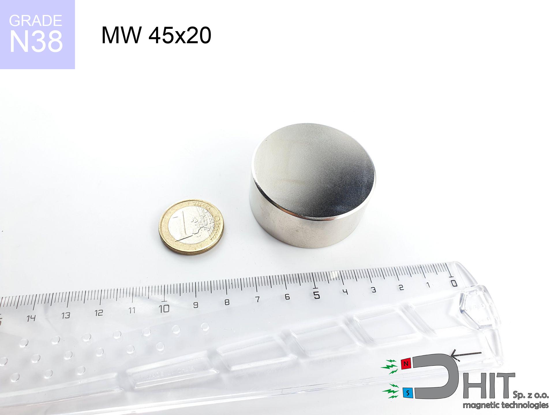
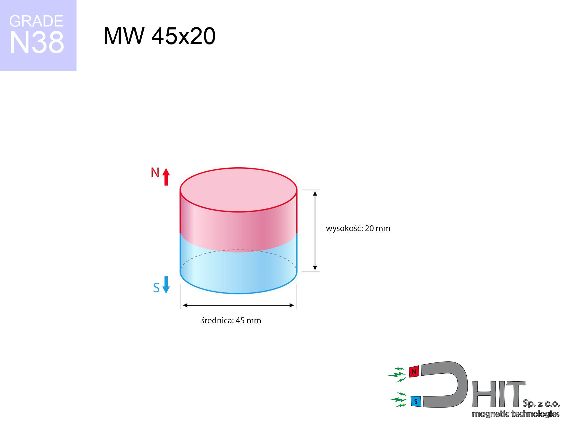
MW 45x20 / N38 - cylindrical magnet
cylindrical magnet
Catalog no 010071
GTIN/EAN: 5906301810704
Diameter Ø
45 mm [±0,1 mm]
Height
20 mm [±0,1 mm]
Weight
238.56 g
Magnetization Direction
↑ axial
Load capacity
60.94 kg / 597.79 N
Magnetic Induction
411.81 mT / 4118 Gs
Coating
[NiCuNi] Nickel
84.45 ZŁ with VAT / pcs + price for transport
68.66 ZŁ net + 23% VAT / pcs
bulk discounts:
Need more?
Pick up the phone and ask
+48 888 99 98 98
or let us know using
request form
the contact form page.
Specifications along with appearance of magnets can be tested on our
magnetic mass calculator.
Same-day shipping for orders placed before 14:00.
Product card - MW 45x20 / N38 - cylindrical magnet
Specification / characteristics - MW 45x20 / N38 - cylindrical magnet
| properties | values |
|---|---|
| Cat. no. | 010071 |
| GTIN/EAN | 5906301810704 |
| Production/Distribution | Dhit sp. z o.o. |
| Country of origin | Poland / China / Germany |
| Customs code | 85059029 |
| Diameter Ø | 45 mm [±0,1 mm] |
| Height | 20 mm [±0,1 mm] |
| Weight | 238.56 g |
| Magnetization Direction | ↑ axial |
| Load capacity ~ ? | 60.94 kg / 597.79 N |
| Magnetic Induction ~ ? | 411.81 mT / 4118 Gs |
| Coating | [NiCuNi] Nickel |
| Manufacturing Tolerance | ±0.1 mm |
Magnetic properties of material N38
| properties | values | units |
|---|---|---|
| remenance Br [min. - max.] ? | 12.2-12.6 | kGs |
| remenance Br [min. - max.] ? | 1220-1260 | mT |
| coercivity bHc ? | 10.8-11.5 | kOe |
| coercivity bHc ? | 860-915 | kA/m |
| actual internal force iHc | ≥ 12 | kOe |
| actual internal force iHc | ≥ 955 | kA/m |
| energy density [min. - max.] ? | 36-38 | BH max MGOe |
| energy density [min. - max.] ? | 287-303 | BH max KJ/m |
| max. temperature ? | ≤ 80 | °C |
Physical properties of sintered neodymium magnets Nd2Fe14B at 20°C
| properties | values | units |
|---|---|---|
| Vickers hardness | ≥550 | Hv |
| Density | ≥7.4 | g/cm3 |
| Curie Temperature TC | 312 - 380 | °C |
| Curie Temperature TF | 593 - 716 | °F |
| Specific resistance | 150 | μΩ⋅cm |
| Bending strength | 250 | MPa |
| Compressive strength | 1000~1100 | MPa |
| Thermal expansion parallel (∥) to orientation (M) | (3-4) x 10-6 | °C-1 |
| Thermal expansion perpendicular (⊥) to orientation (M) | -(1-3) x 10-6 | °C-1 |
| Young's modulus | 1.7 x 10⁴ | kg/mm² |
Engineering analysis of the product - technical parameters
The following values represent the direct effect of a engineering simulation. Results are based on models for the class Nd2Fe14B. Operational parameters might slightly deviate from the simulation results. Treat these calculations as a reference point during assembly planning.
Table 1: Static force (force vs distance) - characteristics
MW 45x20 / N38
| Distance (mm) | Induction (Gauss) / mT | Pull Force (kg/lbs/g/N) | Risk Status |
|---|---|---|---|
| 0 mm |
4117 Gs
411.7 mT
|
60.94 kg / 134.35 LBS
60940.0 g / 597.8 N
|
dangerous! |
| 1 mm |
3955 Gs
395.5 mT
|
56.23 kg / 123.96 LBS
56228.7 g / 551.6 N
|
dangerous! |
| 2 mm |
3786 Gs
378.6 mT
|
51.51 kg / 113.57 LBS
51512.3 g / 505.3 N
|
dangerous! |
| 3 mm |
3613 Gs
361.3 mT
|
46.91 kg / 103.42 LBS
46911.0 g / 460.2 N
|
dangerous! |
| 5 mm |
3263 Gs
326.3 mT
|
38.28 kg / 84.40 LBS
38282.6 g / 375.6 N
|
dangerous! |
| 10 mm |
2442 Gs
244.2 mT
|
21.43 kg / 47.26 LBS
21434.6 g / 210.3 N
|
dangerous! |
| 15 mm |
1776 Gs
177.6 mT
|
11.34 kg / 25.00 LBS
11340.0 g / 111.2 N
|
dangerous! |
| 20 mm |
1285 Gs
128.5 mT
|
5.93 kg / 13.08 LBS
5932.8 g / 58.2 N
|
medium risk |
| 30 mm |
694 Gs
69.4 mT
|
1.73 kg / 3.82 LBS
1730.8 g / 17.0 N
|
weak grip |
| 50 mm |
249 Gs
24.9 mT
|
0.22 kg / 0.49 LBS
222.3 g / 2.2 N
|
weak grip |
Table 2: Vertical load (vertical surface)
MW 45x20 / N38
| Distance (mm) | Friction coefficient | Pull Force (kg/lbs/g/N) |
|---|---|---|
| 0 mm | Stal (~0.2) |
12.19 kg / 26.87 LBS
12188.0 g / 119.6 N
|
| 1 mm | Stal (~0.2) |
11.25 kg / 24.79 LBS
11246.0 g / 110.3 N
|
| 2 mm | Stal (~0.2) |
10.30 kg / 22.71 LBS
10302.0 g / 101.1 N
|
| 3 mm | Stal (~0.2) |
9.38 kg / 20.68 LBS
9382.0 g / 92.0 N
|
| 5 mm | Stal (~0.2) |
7.66 kg / 16.88 LBS
7656.0 g / 75.1 N
|
| 10 mm | Stal (~0.2) |
4.29 kg / 9.45 LBS
4286.0 g / 42.0 N
|
| 15 mm | Stal (~0.2) |
2.27 kg / 5.00 LBS
2268.0 g / 22.2 N
|
| 20 mm | Stal (~0.2) |
1.19 kg / 2.61 LBS
1186.0 g / 11.6 N
|
| 30 mm | Stal (~0.2) |
0.35 kg / 0.76 LBS
346.0 g / 3.4 N
|
| 50 mm | Stal (~0.2) |
0.04 kg / 0.10 LBS
44.0 g / 0.4 N
|
Table 3: Vertical assembly (shearing) - behavior on slippery surfaces
MW 45x20 / N38
| Surface type | Friction coefficient / % Mocy | Max load (kg/lbs/g/N) |
|---|---|---|
| Raw steel |
µ = 0.3
30% Nominalnej Siły
|
18.28 kg / 40.30 LBS
18282.0 g / 179.3 N
|
| Painted steel (standard) |
µ = 0.2
20% Nominalnej Siły
|
12.19 kg / 26.87 LBS
12188.0 g / 119.6 N
|
| Oily/slippery steel |
µ = 0.1
10% Nominalnej Siły
|
6.09 kg / 13.43 LBS
6094.0 g / 59.8 N
|
| Magnet with anti-slip rubber |
µ = 0.5
50% Nominalnej Siły
|
30.47 kg / 67.17 LBS
30470.0 g / 298.9 N
|
Table 4: Steel thickness (saturation) - power losses
MW 45x20 / N38
| Steel thickness (mm) | % power | Real pull force (kg/lbs/g/N) |
|---|---|---|
| 0.5 mm |
|
2.03 kg / 4.48 LBS
2031.3 g / 19.9 N
|
| 1 mm |
|
5.08 kg / 11.20 LBS
5078.3 g / 49.8 N
|
| 2 mm |
|
10.16 kg / 22.39 LBS
10156.7 g / 99.6 N
|
| 3 mm |
|
15.24 kg / 33.59 LBS
15235.0 g / 149.5 N
|
| 5 mm |
|
25.39 kg / 55.98 LBS
25391.7 g / 249.1 N
|
| 10 mm |
|
50.78 kg / 111.96 LBS
50783.3 g / 498.2 N
|
| 11 mm |
|
55.86 kg / 123.15 LBS
55861.7 g / 548.0 N
|
| 12 mm |
|
60.94 kg / 134.35 LBS
60940.0 g / 597.8 N
|
Table 5: Thermal stability (stability) - resistance threshold
MW 45x20 / N38
| Ambient temp. (°C) | Power loss | Remaining pull (kg/lbs/g/N) | Status |
|---|---|---|---|
| 20 °C | 0.0% |
60.94 kg / 134.35 LBS
60940.0 g / 597.8 N
|
OK |
| 40 °C | -2.2% |
59.60 kg / 131.39 LBS
59599.3 g / 584.7 N
|
OK |
| 60 °C | -4.4% |
58.26 kg / 128.44 LBS
58258.6 g / 571.5 N
|
|
| 80 °C | -6.6% |
56.92 kg / 125.48 LBS
56918.0 g / 558.4 N
|
|
| 100 °C | -28.8% |
43.39 kg / 95.66 LBS
43389.3 g / 425.6 N
|
Table 6: Magnet-Magnet interaction (attraction) - field collision
MW 45x20 / N38
| Gap (mm) | Attraction (kg/lbs) (N-S) | Shear Force (kg/lbs/g/N) | Repulsion (kg/lbs) (N-N) |
|---|---|---|---|
| 0 mm |
166.23 kg / 366.47 LBS
5 401 Gs
|
24.93 kg / 54.97 LBS
24934 g / 244.6 N
|
N/A |
| 1 mm |
159.87 kg / 352.45 LBS
8 076 Gs
|
23.98 kg / 52.87 LBS
23980 g / 235.2 N
|
143.88 kg / 317.20 LBS
~0 Gs
|
| 2 mm |
153.38 kg / 338.14 LBS
7 910 Gs
|
23.01 kg / 50.72 LBS
23007 g / 225.7 N
|
138.04 kg / 304.33 LBS
~0 Gs
|
| 3 mm |
146.92 kg / 323.90 LBS
7 742 Gs
|
22.04 kg / 48.58 LBS
22038 g / 216.2 N
|
132.23 kg / 291.51 LBS
~0 Gs
|
| 5 mm |
134.19 kg / 295.83 LBS
7 399 Gs
|
20.13 kg / 44.37 LBS
20128 g / 197.5 N
|
120.77 kg / 266.25 LBS
~0 Gs
|
| 10 mm |
104.43 kg / 230.22 LBS
6 527 Gs
|
15.66 kg / 34.53 LBS
15664 g / 153.7 N
|
93.98 kg / 207.20 LBS
~0 Gs
|
| 20 mm |
58.47 kg / 128.90 LBS
4 884 Gs
|
8.77 kg / 19.34 LBS
8770 g / 86.0 N
|
52.62 kg / 116.01 LBS
~0 Gs
|
| 50 mm |
8.61 kg / 18.98 LBS
1 874 Gs
|
1.29 kg / 2.85 LBS
1291 g / 12.7 N
|
7.75 kg / 17.08 LBS
~0 Gs
|
| 60 mm |
4.72 kg / 10.41 LBS
1 388 Gs
|
0.71 kg / 1.56 LBS
708 g / 6.9 N
|
4.25 kg / 9.37 LBS
~0 Gs
|
| 70 mm |
2.68 kg / 5.91 LBS
1 046 Gs
|
0.40 kg / 0.89 LBS
402 g / 3.9 N
|
2.41 kg / 5.32 LBS
~0 Gs
|
| 80 mm |
1.58 kg / 3.48 LBS
803 Gs
|
0.24 kg / 0.52 LBS
237 g / 2.3 N
|
1.42 kg / 3.14 LBS
~0 Gs
|
| 90 mm |
0.96 kg / 2.12 LBS
627 Gs
|
0.14 kg / 0.32 LBS
145 g / 1.4 N
|
0.87 kg / 1.91 LBS
~0 Gs
|
| 100 mm |
0.61 kg / 1.34 LBS
497 Gs
|
0.09 kg / 0.20 LBS
91 g / 0.9 N
|
0.55 kg / 1.20 LBS
~0 Gs
|
Table 7: Hazards (implants) - precautionary measures
MW 45x20 / N38
| Object / Device | Limit (Gauss) / mT | Safe distance |
|---|---|---|
| Pacemaker | 5 Gs (0.5 mT) | 22.5 cm |
| Hearing aid | 10 Gs (1.0 mT) | 17.5 cm |
| Mechanical watch | 20 Gs (2.0 mT) | 14.0 cm |
| Phone / Smartphone | 40 Gs (4.0 mT) | 10.5 cm |
| Car key | 50 Gs (5.0 mT) | 10.0 cm |
| Payment card | 400 Gs (40.0 mT) | 4.5 cm |
| HDD hard drive | 600 Gs (60.0 mT) | 3.5 cm |
Table 8: Collisions (kinetic energy) - collision effects
MW 45x20 / N38
| Start from (mm) | Speed (km/h) | Energy (J) | Predicted outcome |
|---|---|---|---|
| 10 mm |
19.34 km/h
(5.37 m/s)
|
3.44 J | |
| 30 mm |
28.41 km/h
(7.89 m/s)
|
7.43 J | |
| 50 mm |
36.12 km/h
(10.03 m/s)
|
12.01 J | |
| 100 mm |
50.98 km/h
(14.16 m/s)
|
23.92 J |
Table 9: Coating parameters (durability)
MW 45x20 / N38
| Technical parameter | Value / Description |
|---|---|
| Coating type | [NiCuNi] Nickel |
| Layer structure | Nickel - Copper - Nickel |
| Layer thickness | 10-20 µm |
| Salt spray test (SST) ? | 24 h |
| Recommended environment | Indoors only (dry) |
Table 10: Electrical data (Flux)
MW 45x20 / N38
| Parameter | Value | SI Unit / Description |
|---|---|---|
| Magnetic Flux | 66 952 Mx | 669.5 µWb |
| Pc Coefficient | 0.54 | Low (Flat) |
Table 11: Submerged application
MW 45x20 / N38
| Environment | Effective steel pull | Effect |
|---|---|---|
| Air (land) | 60.94 kg | Standard |
| Water (riverbed) |
69.78 kg
(+8.84 kg buoyancy gain)
|
+14.5% |
1. Shear force
*Caution: On a vertical surface, the magnet holds merely a fraction of its max power.
2. Steel thickness impact
*Thin steel (e.g. computer case) drastically weakens the holding force.
3. Thermal stability
*For N38 material, the max working temp is 80°C.
4. Demagnetization curve and operating point (B-H)
chart generated for the permeance coefficient Pc (Permeance Coefficient) = 0.54
This simulation demonstrates the magnetic stability of the selected magnet under specific geometric conditions. The solid red line represents the demagnetization curve (material potential), while the dashed blue line is the load line based on the magnet's geometry. The Pc (Permeance Coefficient), also known as the load line slope, is a dimensionless value that describes the relationship between the magnet's shape and its magnetic stability. The intersection of these two lines (the black dot) is the operating point — it determines the actual magnetic flux density generated by the magnet in this specific configuration. A higher Pc value means the magnet is more 'slender' (tall relative to its area), resulting in a higher operating point and better resistance to irreversible demagnetization caused by external fields or temperature. A value of 0.42 is relatively low (typical for flat magnets), meaning the operating point is closer to the 'knee' of the curve — caution is advised when operating at temperatures near the maximum limit to avoid strength loss.
Elemental analysis
| iron (Fe) | 64% – 68% |
| neodymium (Nd) | 29% – 32% |
| boron (B) | 1.1% – 1.2% |
| dysprosium (Dy) | 0.5% – 2.0% |
| coating (Ni-Cu-Ni) | < 0.05% |
Environmental data
| recyclability (EoL) | 100% |
| recycled raw materials | ~10% (pre-cons) |
| carbon footprint | low / zredukowany |
| waste code (EWC) | 16 02 16 |
Other proposals

![UMH 20x7x35 [M4] / N38 - magnetic holder with hook](https://cdn3.dhit.pl/graphics/products/umh-20x7x35-m4-hiz.jpg "UMH 20x7x35 [M4] / N38 - magnetic holder with hook")


Advantages as well as disadvantages of rare earth magnets.
Benefits
- They have stable power, and over more than 10 years their performance decreases symbolically – ~1% (in testing),
- They maintain their magnetic properties even under close interference source,
- The use of an metallic coating of noble metals (nickel, gold, silver) causes the element to have aesthetics,
- They feature high magnetic induction at the operating surface, which affects their effectiveness,
- Due to their durability and thermal resistance, neodymium magnets can operate (depending on the shape) even at high temperatures reaching 230°C or more...
- Considering the option of precise shaping and customization to specialized requirements, NdFeB magnets can be produced in a broad palette of geometric configurations, which increases their versatility,
- Fundamental importance in electronics industry – they are utilized in HDD drives, motor assemblies, diagnostic systems, as well as modern systems.
- Relatively small size with high pulling force – neodymium magnets offer strong magnetic field in compact dimensions, which makes them useful in compact constructions
Weaknesses
- They are prone to damage upon heavy impacts. To avoid cracks, it is worth securing magnets in a protective case. Such protection not only protects the magnet but also increases its resistance to damage
- We warn that neodymium magnets can reduce their strength at high temperatures. To prevent this, we suggest our specialized [AH] magnets, which work effectively even at 230°C.
- Due to the susceptibility of magnets to corrosion in a humid environment, we recommend using waterproof magnets made of rubber, plastic or other material resistant to moisture, when using outdoors
- Due to limitations in realizing nuts and complex shapes in magnets, we recommend using cover - magnetic mechanism.
- Possible danger to health – tiny shards of magnets pose a threat, in case of ingestion, which gains importance in the context of child health protection. Additionally, tiny parts of these magnets are able to disrupt the diagnostic process medical when they are in the body.
- Due to neodymium price, their price exceeds standard values,
Lifting parameters
Magnetic strength at its maximum – what it depends on?
- using a base made of high-permeability steel, acting as a circuit closing element
- possessing a thickness of minimum 10 mm to ensure full flux closure
- with a plane free of scratches
- under conditions of no distance (surface-to-surface)
- during detachment in a direction vertical to the mounting surface
- at conditions approx. 20°C
Practical aspects of lifting capacity – factors
- Air gap (betwixt the magnet and the metal), because even a tiny clearance (e.g. 0.5 mm) results in a decrease in lifting capacity by up to 50% (this also applies to varnish, rust or debris).
- Force direction – remember that the magnet has greatest strength perpendicularly. Under sliding down, the capacity drops drastically, often to levels of 20-30% of the nominal value.
- Metal thickness – the thinner the sheet, the weaker the hold. Part of the magnetic field penetrates through instead of generating force.
- Metal type – different alloys attracts identically. Alloy additives worsen the attraction effect.
- Surface finish – full contact is obtained only on smooth steel. Rough texture reduce the real contact area, reducing force.
- Temperature – temperature increase causes a temporary drop of induction. It is worth remembering the thermal limit for a given model.
Lifting capacity testing was conducted on a smooth plate of optimal thickness, under a perpendicular pulling force, however under attempts to slide the magnet the load capacity is reduced by as much as fivefold. Moreover, even a slight gap between the magnet’s surface and the plate decreases the lifting capacity.
H&S for magnets
Combustion hazard
Powder produced during cutting of magnets is flammable. Do not drill into magnets unless you are an expert.
Pinching danger
Watch your fingers. Two powerful magnets will join immediately with a force of several hundred kilograms, destroying anything in their path. Be careful!
Thermal limits
Keep cool. NdFeB magnets are sensitive to heat. If you require resistance above 80°C, look for special high-temperature series (H, SH, UH).
Shattering risk
Neodymium magnets are sintered ceramics, which means they are fragile like glass. Collision of two magnets will cause them cracking into shards.
Phone sensors
Note: neodymium magnets generate a field that confuses precision electronics. Maintain a separation from your mobile, tablet, and navigation systems.
Keep away from computers
Intense magnetic fields can destroy records on credit cards, hard drives, and other magnetic media. Keep a distance of at least 10 cm.
This is not a toy
Always keep magnets away from children. Ingestion danger is significant, and the consequences of magnets connecting inside the body are very dangerous.
Allergic reactions
A percentage of the population experience a contact allergy to Ni, which is the typical protective layer for neodymium magnets. Prolonged contact might lead to a rash. We strongly advise wear safety gloves.
Life threat
Life threat: Strong magnets can turn off heart devices and defibrillators. Stay away if you have medical devices.
Handling rules
Before use, check safety instructions. Uncontrolled attraction can break the magnet or injure your hand. Think ahead.
Tabela kosztu i czasu dostawy
Płatność przed wysyłką:

GLS kurier
Przesyłka będzie u Ciebie za 2-3 dni
14.99 ZŁ

InPost Paczkomaty 24/7
Przesyłka będzie u Ciebie za 1-2 dni
12.30 ZŁ
Płatność przy odbiorze (pobranie):
GLS kurier
Przesyłka będzie u Ciebie za 1-2 dni
23.00 ZŁ
Rate the product
Your rating