
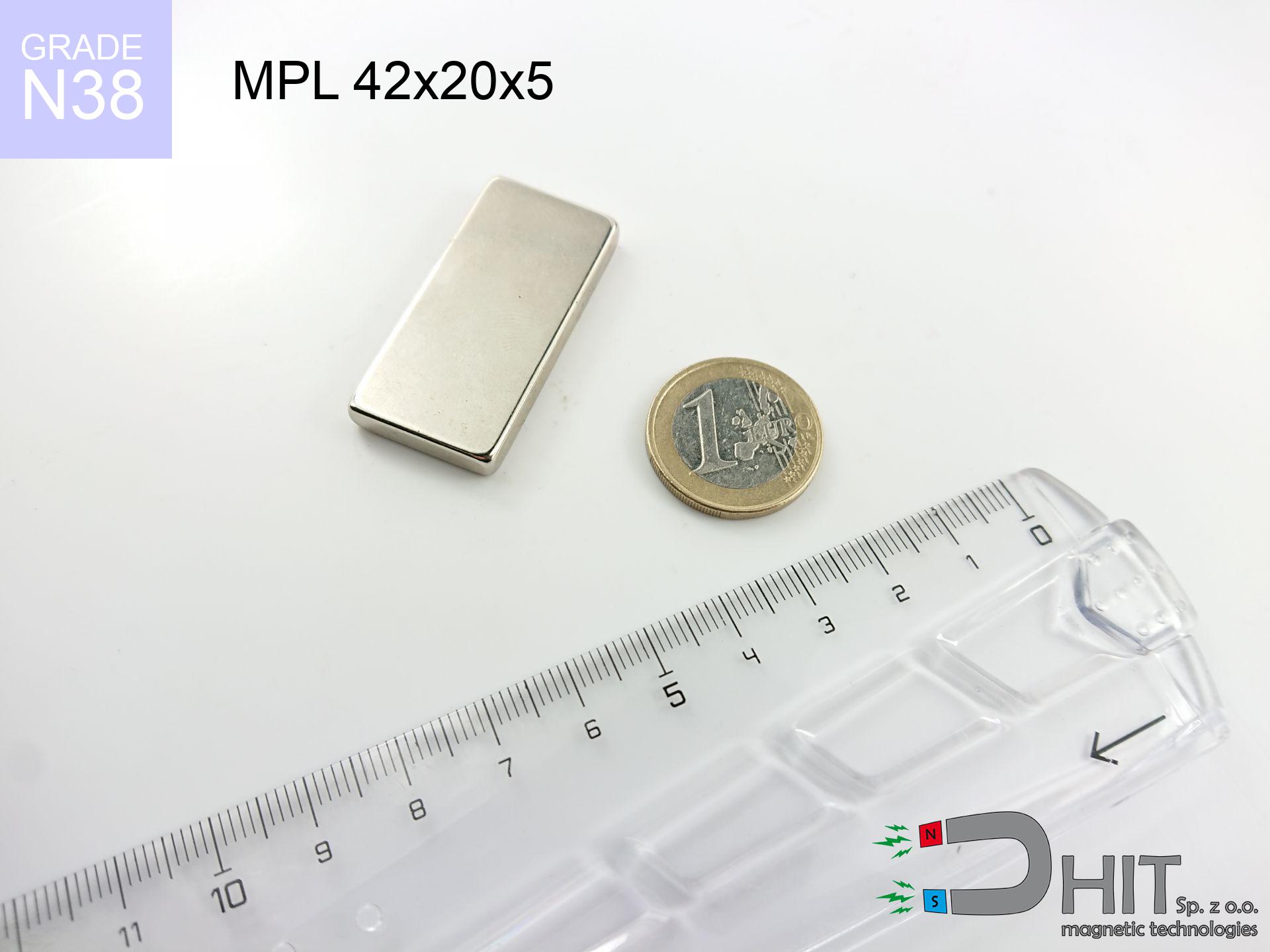
MPL 42x20x5 / N38 - lamellar magnet
lamellar magnet
Catalog no 020163
GTIN/EAN: 5906301811695
length
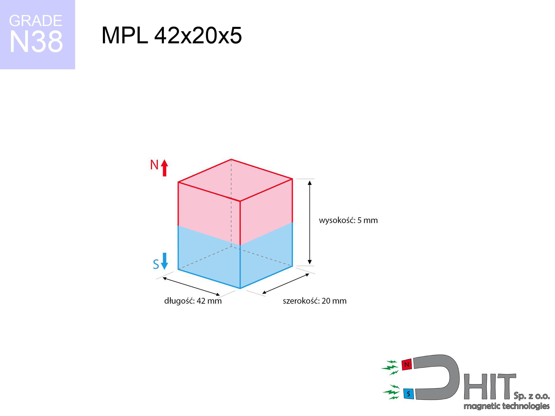
42 mm [±0,1 mm]
Width
20 mm [±0,1 mm]
Height
5 mm [±0,1 mm]
Weight
31.5 g
Magnetization Direction
↑ axial
Load capacity
11.06 kg / 108.46 N
Magnetic Induction
203.37 mT / 2034 Gs
Coating
[NiCuNi] Nickel
15.62 ZŁ with VAT / pcs + price for transport
12.70 ZŁ net + 23% VAT / pcs
bulk discounts:
Need more?Engineering report for this magnet
Full PDF analysis: pull and shear force, effect of distance, temperature and plate thickness, safety distances and the demagnetization curve.
Call us now
+48 22 499 98 98
otherwise contact us by means of
inquiry form
through our site.
Specifications and structure of neodymium magnets can be reviewed with our
online calculation tool.
Orders submitted before 14:00 will be dispatched today!
Physical properties - MPL 42x20x5 / N38 - lamellar magnet
Specification / characteristics - MPL 42x20x5 / N38 - lamellar magnet
| properties | values |
|---|---|
| Cat. no. | 020163 |
| GTIN/EAN | 5906301811695 |
| Production/Distribution | Dhit sp. z o.o. |
| Country of origin | Poland / China / Germany |
| Customs code | 85059029 |
| length | 42 mm [±0,1 mm] |
| Width | 20 mm [±0,1 mm] |
| Height | 5 mm [±0,1 mm] |
| Weight | 31.5 g |
| Magnetization Direction | ↑ axial |
| Load capacity ~ ? | 11.06 kg / 108.46 N |
| Magnetic Induction ~ ? | 203.37 mT / 2034 Gs |
| Coating | [NiCuNi] Nickel |
| Manufacturing Tolerance | ±0.1 mm |
Magnetic properties of material N38
| properties | values | units |
|---|---|---|
| remenance Br [min. - max.] ? | 12.2-12.6 | kGs |
| remenance Br [min. - max.] ? | 1220-1260 | mT |
| coercivity bHc ? | 10.8-11.5 | kOe |
| coercivity bHc ? | 860-915 | kA/m |
| actual internal force iHc | ≥ 12 | kOe |
| actual internal force iHc | ≥ 955 | kA/m |
| energy density [min. - max.] ? | 36-38 | BH max MGOe |
| energy density [min. - max.] ? | 287-303 | BH max KJ/m |
| max. temperature ? | ≤ 80 | °C |
Physical properties of sintered neodymium magnets Nd2Fe14B at 20°C
| properties | values | units |
|---|---|---|
| Vickers hardness | ≥550 | Hv |
| Density | ≥7.4 | g/cm3 |
| Curie Temperature TC | 312 - 380 | °C |
| Curie Temperature TF | 593 - 716 | °F |
| Specific resistance | 150 | μΩ⋅cm |
| Bending strength | 250 | MPa |
| Compressive strength | 1000~1100 | MPa |
| Thermal expansion parallel (∥) to orientation (M) | (3-4) x 10-6 | °C-1 |
| Thermal expansion perpendicular (⊥) to orientation (M) | -(1-3) x 10-6 | °C-1 |
| Young's modulus | 1.7 x 10⁴ | kg/mm² |
Engineering modeling of the assembly - data
These data represent the direct effect of a engineering analysis. Values are based on algorithms for the material Nd2Fe14B. Actual parameters may deviate from the simulation results. Use these data as a preliminary roadmap when designing systems.
Table 1: Static pull force (pull vs gap) - power drop
MPL 42x20x5 / N38
| Distance (mm) | Induction (Gauss) / mT | Pull Force (kg/lbs/g/N) | Risk Status |
|---|---|---|---|
| 0 mm |
2033 Gs
203.3 mT
|
11.06 kg / 24.38 pounds
11060.0 g / 108.5 N
|
crushing |
| 1 mm |
1938 Gs
193.8 mT
|
10.05 kg / 22.15 pounds
10049.3 g / 98.6 N
|
crushing |
| 2 mm |
1823 Gs
182.3 mT
|
8.89 kg / 19.60 pounds
8888.2 g / 87.2 N
|
warning |
| 3 mm |
1696 Gs
169.6 mT
|
7.69 kg / 16.96 pounds
7691.7 g / 75.5 N
|
warning |
| 5 mm |
1433 Gs
143.3 mT
|
5.49 kg / 12.10 pounds
5490.3 g / 53.9 N
|
warning |
| 10 mm |
885 Gs
88.5 mT
|
2.09 kg / 4.62 pounds
2093.5 g / 20.5 N
|
warning |
| 15 mm |
547 Gs
54.7 mT
|
0.80 kg / 1.76 pounds
799.6 g / 7.8 N
|
safe |
| 20 mm |
350 Gs
35.0 mT
|
0.33 kg / 0.72 pounds
327.0 g / 3.2 N
|
safe |
| 30 mm |
160 Gs
16.0 mT
|
0.07 kg / 0.15 pounds
68.5 g / 0.7 N
|
safe |
| 50 mm |
48 Gs
4.8 mT
|
0.01 kg / 0.01 pounds
6.2 g / 0.1 N
|
safe |
Table 2: Vertical hold (wall)
MPL 42x20x5 / N38
| Distance (mm) | Friction coefficient | Pull Force (kg/lbs/g/N) |
|---|---|---|
| 0 mm | Stal (~0.2) |
2.21 kg / 4.88 pounds
2212.0 g / 21.7 N
|
| 1 mm | Stal (~0.2) |
2.01 kg / 4.43 pounds
2010.0 g / 19.7 N
|
| 2 mm | Stal (~0.2) |
1.78 kg / 3.92 pounds
1778.0 g / 17.4 N
|
| 3 mm | Stal (~0.2) |
1.54 kg / 3.39 pounds
1538.0 g / 15.1 N
|
| 5 mm | Stal (~0.2) |
1.10 kg / 2.42 pounds
1098.0 g / 10.8 N
|
| 10 mm | Stal (~0.2) |
0.42 kg / 0.92 pounds
418.0 g / 4.1 N
|
| 15 mm | Stal (~0.2) |
0.16 kg / 0.35 pounds
160.0 g / 1.6 N
|
| 20 mm | Stal (~0.2) |
0.07 kg / 0.15 pounds
66.0 g / 0.6 N
|
| 30 mm | Stal (~0.2) |
0.01 kg / 0.03 pounds
14.0 g / 0.1 N
|
| 50 mm | Stal (~0.2) |
0.00 kg / 0.00 pounds
2.0 g / 0.0 N
|
Table 3: Wall mounting (shearing) - behavior on slippery surfaces
MPL 42x20x5 / N38
| Surface type | Friction coefficient / % Mocy | Max load (kg/lbs/g/N) |
|---|---|---|
| Raw steel |
µ = 0.3
30% Nominalnej Siły
|
3.32 kg / 7.31 pounds
3318.0 g / 32.5 N
|
| Painted steel (standard) |
µ = 0.2
20% Nominalnej Siły
|
2.21 kg / 4.88 pounds
2212.0 g / 21.7 N
|
| Oily/slippery steel |
µ = 0.1
10% Nominalnej Siły
|
1.11 kg / 2.44 pounds
1106.0 g / 10.8 N
|
| Magnet with anti-slip rubber |
µ = 0.5
50% Nominalnej Siły
|
5.53 kg / 12.19 pounds
5530.0 g / 54.2 N
|
Table 4: Material efficiency (substrate influence) - power losses
MPL 42x20x5 / N38
| Steel thickness (mm) | % power | Real pull force (kg/lbs/g/N) |
|---|---|---|
| 0.5 mm |
|
0.55 kg / 1.22 pounds
553.0 g / 5.4 N
|
| 1 mm |
|
1.38 kg / 3.05 pounds
1382.5 g / 13.6 N
|
| 2 mm |
|
2.77 kg / 6.10 pounds
2765.0 g / 27.1 N
|
| 3 mm |
|
4.15 kg / 9.14 pounds
4147.5 g / 40.7 N
|
| 5 mm |
|
6.91 kg / 15.24 pounds
6912.5 g / 67.8 N
|
| 10 mm |
|
11.06 kg / 24.38 pounds
11060.0 g / 108.5 N
|
| 11 mm |
|
11.06 kg / 24.38 pounds
11060.0 g / 108.5 N
|
| 12 mm |
|
11.06 kg / 24.38 pounds
11060.0 g / 108.5 N
|
Table 5: Thermal stability (material behavior) - thermal limit
MPL 42x20x5 / N38
| Ambient temp. (°C) | Power loss | Remaining pull (kg/lbs/g/N) | Status |
|---|---|---|---|
| 20 °C | 0.0% |
11.06 kg / 24.38 pounds
11060.0 g / 108.5 N
|
OK |
| 40 °C | -2.2% |
10.82 kg / 23.85 pounds
10816.7 g / 106.1 N
|
OK |
| 60 °C | -4.4% |
10.57 kg / 23.31 pounds
10573.4 g / 103.7 N
|
|
| 80 °C | -6.6% |
10.33 kg / 22.77 pounds
10330.0 g / 101.3 N
|
|
| 100 °C | -28.8% |
7.87 kg / 17.36 pounds
7874.7 g / 77.3 N
|
Table 6: Magnet-Magnet interaction (attraction) - forces in the system
MPL 42x20x5 / N38
| Gap (mm) | Attraction (kg/lbs) (N-S) | Sliding Force (kg/lbs/g/N) | Repulsion (kg/lbs) (N-N) |
|---|---|---|---|
| 0 mm |
21.41 kg / 47.21 pounds
3 465 Gs
|
3.21 kg / 7.08 pounds
3212 g / 31.5 N
|
N/A |
| 1 mm |
20.49 kg / 45.17 pounds
3 978 Gs
|
3.07 kg / 6.78 pounds
3074 g / 30.2 N
|
18.44 kg / 40.66 pounds
~0 Gs
|
| 2 mm |
19.46 kg / 42.89 pounds
3 877 Gs
|
2.92 kg / 6.43 pounds
2918 g / 28.6 N
|
17.51 kg / 38.60 pounds
~0 Gs
|
| 3 mm |
18.35 kg / 40.46 pounds
3 765 Gs
|
2.75 kg / 6.07 pounds
2753 g / 27.0 N
|
16.52 kg / 36.41 pounds
~0 Gs
|
| 5 mm |
16.05 kg / 35.38 pounds
3 521 Gs
|
2.41 kg / 5.31 pounds
2407 g / 23.6 N
|
14.44 kg / 31.84 pounds
~0 Gs
|
| 10 mm |
10.63 kg / 23.43 pounds
2 865 Gs
|
1.59 kg / 3.52 pounds
1594 g / 15.6 N
|
9.57 kg / 21.09 pounds
~0 Gs
|
| 20 mm |
4.05 kg / 8.94 pounds
1 769 Gs
|
0.61 kg / 1.34 pounds
608 g / 6.0 N
|
3.65 kg / 8.04 pounds
~0 Gs
|
| 50 mm |
0.28 kg / 0.62 pounds
465 Gs
|
0.04 kg / 0.09 pounds
42 g / 0.4 N
|
0.25 kg / 0.55 pounds
~0 Gs
|
| 60 mm |
0.13 kg / 0.29 pounds
320 Gs
|
0.02 kg / 0.04 pounds
20 g / 0.2 N
|
0.12 kg / 0.26 pounds
~0 Gs
|
| 70 mm |
0.07 kg / 0.15 pounds
228 Gs
|
0.01 kg / 0.02 pounds
10 g / 0.1 N
|
0.06 kg / 0.13 pounds
~0 Gs
|
| 80 mm |
0.04 kg / 0.08 pounds
167 Gs
|
0.01 kg / 0.01 pounds
5 g / 0.1 N
|
0.03 kg / 0.07 pounds
~0 Gs
|
| 90 mm |
0.02 kg / 0.04 pounds
125 Gs
|
0.00 kg / 0.01 pounds
3 g / 0.0 N
|
0.02 kg / 0.04 pounds
~0 Gs
|
| 100 mm |
0.01 kg / 0.03 pounds
96 Gs
|
0.00 kg / 0.00 pounds
2 g / 0.0 N
|
0.01 kg / 0.02 pounds
~0 Gs
|
Table 7: Safety (HSE) (electronics) - precautionary measures
MPL 42x20x5 / N38
| Object / Device | Limit (Gauss) / mT | Safe distance |
|---|---|---|
| Pacemaker | 5 Gs (0.5 mT) | 11.5 cm |
| Hearing aid | 10 Gs (1.0 mT) | 9.0 cm |
| Timepiece | 20 Gs (2.0 mT) | 7.0 cm |
| Mobile device | 40 Gs (4.0 mT) | 5.5 cm |
| Remote | 50 Gs (5.0 mT) | 5.0 cm |
| Payment card | 400 Gs (40.0 mT) | 2.0 cm |
| HDD hard drive | 600 Gs (60.0 mT) | 1.5 cm |
Table 8: Impact energy (cracking risk) - collision effects
MPL 42x20x5 / N38
| Start from (mm) | Speed (km/h) | Energy (J) | Predicted outcome |
|---|---|---|---|
| 10 mm |
21.01 km/h
(5.84 m/s)
|
0.54 J | |
| 30 mm |
32.86 km/h
(9.13 m/s)
|
1.31 J | |
| 50 mm |
42.27 km/h
(11.74 m/s)
|
2.17 J | |
| 100 mm |
59.76 km/h
(16.60 m/s)
|
4.34 J |
Table 9: Coating parameters (durability)
MPL 42x20x5 / N38
| Technical parameter | Value / Description |
|---|---|
| Coating type | [NiCuNi] Nickel |
| Layer structure | Nickel - Copper - Nickel |
| Layer thickness | 10-20 µm |
| Salt spray test (SST) ? | 24 h |
| Recommended environment | Indoors only (dry) |
Table 10: Construction data (Pc)
MPL 42x20x5 / N38
| Parameter | Value | SI Unit / Description |
|---|---|---|
| Magnetic Flux | 18 614 Mx | 186.1 µWb |
| Pc Coefficient | 0.23 | Low (Flat) |
Table 11: Hydrostatics and buoyancy
MPL 42x20x5 / N38
| Environment | Effective steel pull | Effect |
|---|---|---|
| Air (land) | 11.06 kg | Standard |
| Water (riverbed) |
12.66 kg
(+1.60 kg buoyancy gain)
|
+14.5% |
1. Vertical hold
*Note: On a vertical wall, the magnet holds only ~20% of its perpendicular strength.
2. Efficiency vs thickness
*Thin metal sheet (e.g. computer case) severely limits the holding force.
3. Temperature resistance
*For N38 grade, the max working temp is 80°C.
4. Demagnetization curve and operating point (B-H)
chart generated for the permeance coefficient Pc (Permeance Coefficient) = 0.23
The chart above illustrates the magnetic characteristics of the material within the second quadrant of the hysteresis loop. The solid red line represents the demagnetization curve (material potential), while the dashed blue line is the load line based on the magnet's geometry. The Pc (Permeance Coefficient), also known as the load line slope, is a dimensionless value that describes the relationship between the magnet's shape and its magnetic stability. The intersection of these two lines (the black dot) is the operating point — it determines the actual magnetic flux density generated by the magnet in this specific configuration. A higher Pc value means the magnet is more 'slender' (tall relative to its area), resulting in a higher operating point and better resistance to irreversible demagnetization caused by external fields or temperature. A value of 0.42 is relatively low (typical for flat magnets), meaning the operating point is closer to the 'knee' of the curve — caution is advised when operating at temperatures near the maximum limit to avoid strength loss.
Elemental analysis
| iron (Fe) | 64% – 68% |
| neodymium (Nd) | 29% – 32% |
| boron (B) | 1.1% – 1.2% |
| dysprosium (Dy) | 0.5% – 2.0% |
| coating (Ni-Cu-Ni) | < 0.05% |
Ecology and recycling (GPSR)
| recyclability (EoL) | 100% |
| recycled raw materials | ~10% (pre-cons) |
| carbon footprint | low / zredukowany |
| waste code (EWC) | 16 02 16 |
View also offers
![UMGGZ 43x6 [M6] GZ / N38 - rubber magnetic holder external thread](https://cdn3.dhit.pl/graphics/products/umg-43x6-m6-gz-miw.jpg "UMGGZ 43x6 [M6] GZ / N38 - rubber magnetic holder external thread")


Pros as well as cons of Nd2Fe14B magnets.
Benefits
- They have constant strength, and over around 10 years their attraction force decreases symbolically – ~1% (according to theory),
- Neodymium magnets are distinguished by remarkably resistant to loss of magnetic properties caused by external interference,
- The use of an aesthetic finish of noble metals (nickel, gold, silver) causes the element to look better,
- Magnets are characterized by maximum magnetic induction on the working surface,
- Through (appropriate) combination of ingredients, they can achieve high thermal resistance, enabling operation at temperatures reaching 230°C and above...
- Thanks to versatility in forming and the ability to adapt to client solutions,
- Versatile presence in high-tech industry – they serve a role in magnetic memories, motor assemblies, medical equipment, as well as other advanced devices.
- Relatively small size with high pulling force – neodymium magnets offer impressive pulling force in compact dimensions, which makes them useful in miniature devices
Cons
- To avoid cracks under impact, we suggest using special steel holders. Such a solution protects the magnet and simultaneously increases its durability.
- When exposed to high temperature, neodymium magnets suffer a drop in force. Often, when the temperature exceeds 80°C, their power decreases (depending on the size and shape of the magnet). For those who need magnets for extreme conditions, we offer [AH] versions withstanding up to 230°C
- Magnets exposed to a humid environment can rust. Therefore during using outdoors, we recommend using water-impermeable magnets made of rubber, plastic or other material protecting against moisture
- Due to limitations in producing threads and complex shapes in magnets, we propose using casing - magnetic mount.
- Health risk to health – tiny shards of magnets can be dangerous, in case of ingestion, which is particularly important in the aspect of protecting the youngest. Additionally, small elements of these devices are able to complicate diagnosis medical after entering the body.
- Higher cost of purchase is one of the disadvantages compared to ceramic magnets, especially in budget applications
Holding force characteristics
Maximum lifting force for a neodymium magnet – what contributes to it?
- on a base made of structural steel, optimally conducting the magnetic field
- with a cross-section no less than 10 mm
- with an ideally smooth contact surface
- without the slightest clearance between the magnet and steel
- during pulling in a direction perpendicular to the plane
- at temperature room level
What influences lifting capacity in practice
- Gap between surfaces – every millimeter of distance (caused e.g. by varnish or unevenness) diminishes the pulling force, often by half at just 0.5 mm.
- Loading method – declared lifting capacity refers to pulling vertically. When slipping, the magnet exhibits much less (typically approx. 20-30% of maximum force).
- Metal thickness – thin material does not allow full use of the magnet. Magnetic flux passes through the material instead of converting into lifting capacity.
- Material composition – different alloys attracts identically. High carbon content worsen the attraction effect.
- Surface condition – ground elements guarantee perfect abutment, which increases field saturation. Uneven metal weaken the grip.
- Operating temperature – neodymium magnets have a negative temperature coefficient. When it is hot they lose power, and in frost they can be stronger (up to a certain limit).
Lifting capacity testing was performed on plates with a smooth surface of suitable thickness, under perpendicular forces, in contrast under shearing force the holding force is lower. Moreover, even a small distance between the magnet and the plate reduces the holding force.
Warnings
Handling rules
Handle magnets with awareness. Their powerful strength can surprise even experienced users. Be vigilant and do not underestimate their power.
Hand protection
Big blocks can break fingers instantly. Under no circumstances put your hand between two attracting surfaces.
Do not give to children
Strictly store magnets away from children. Choking hazard is high, and the consequences of magnets clamping inside the body are life-threatening.
Shattering risk
NdFeB magnets are ceramic materials, which means they are very brittle. Clashing of two magnets will cause them shattering into shards.
Allergic reactions
Nickel alert: The Ni-Cu-Ni coating contains nickel. If an allergic reaction appears, cease handling magnets and use protective gear.
GPS and phone interference
A powerful magnetic field negatively affects the operation of magnetometers in smartphones and navigation systems. Do not bring magnets close to a smartphone to prevent damaging the sensors.
Danger to pacemakers
Life threat: Strong magnets can deactivate pacemakers and defibrillators. Stay away if you have medical devices.
Mechanical processing
Combustion risk: Rare earth powder is explosive. Do not process magnets in home conditions as this risks ignition.
Data carriers
Avoid bringing magnets close to a wallet, computer, or screen. The magnetism can permanently damage these devices and wipe information from cards.
Heat sensitivity
Monitor thermal conditions. Exposing the magnet above 80 degrees Celsius will destroy its magnetic structure and strength.
Tabela kosztu i czasu dostawy
Płatność przed wysyłką:

GLS kurier
Przesyłka będzie u Ciebie za 2-3 dni
14.99 ZŁ

InPost Paczkomaty 24/7
Przesyłka będzie u Ciebie za 1-2 dni
12.30 ZŁ
Płatność przy odbiorze (pobranie):
GLS kurier
Przesyłka będzie u Ciebie za 1-2 dni
23.00 ZŁ
Rate the product
Your rating