
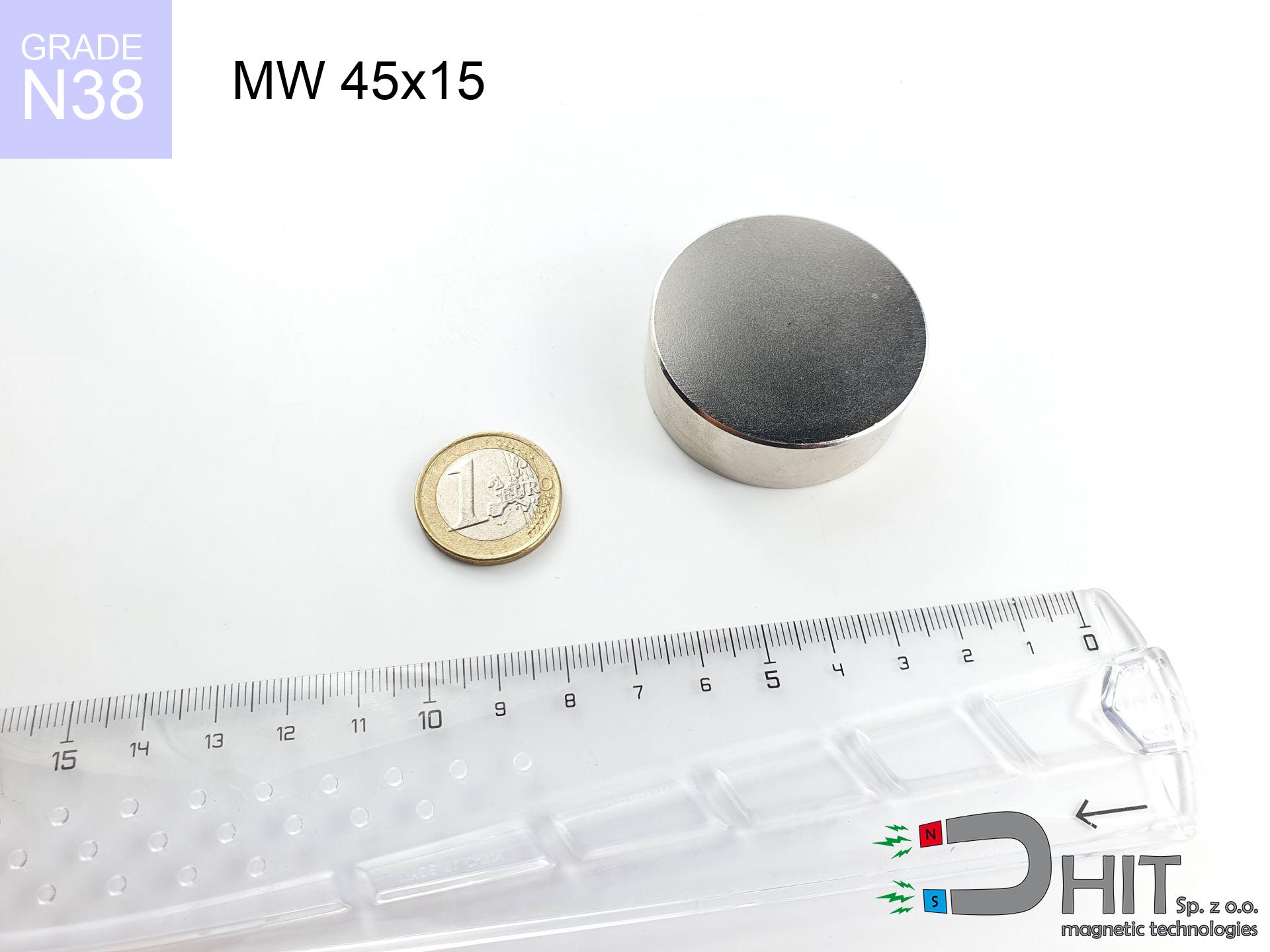
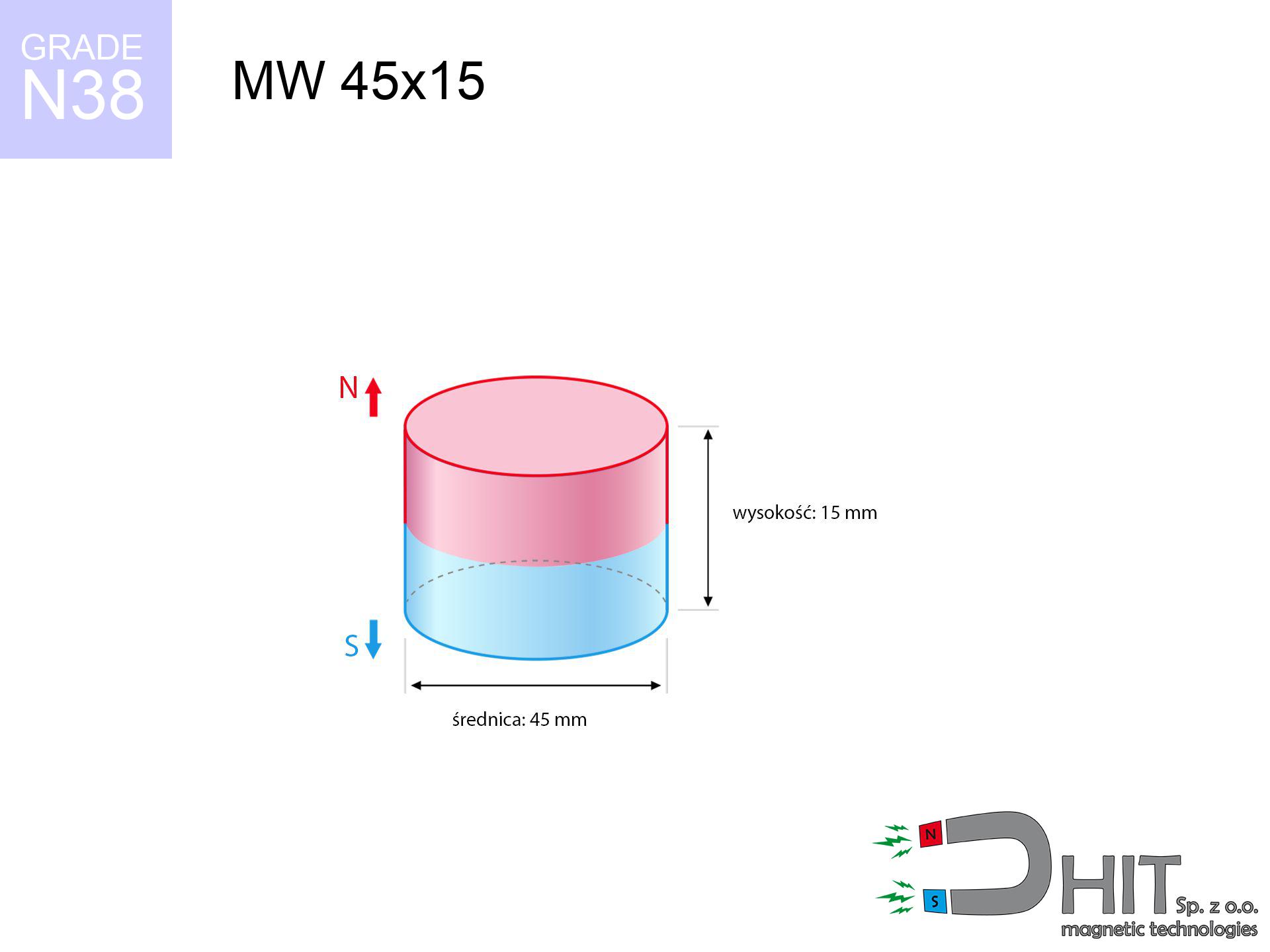
MW 45x15 / N38 - cylindrical magnet
cylindrical magnet
Catalog no 010070
GTIN/EAN: 5906301810698
Diameter Ø
45 mm [±0,1 mm]
Height
15 mm [±0,1 mm]
Weight
178.92 g
Magnetization Direction
↑ axial
Load capacity
48.55 kg / 476.32 N
Magnetic Induction
343.84 mT / 3438 Gs
Coating
[NiCuNi] Nickel
61.84 ZŁ with VAT / pcs + price for transport
50.28 ZŁ net + 23% VAT / pcs
bulk discounts:
Need more?Engineering report for this magnet
Full PDF analysis: pull and shear force, effect of distance, temperature and plate thickness, safety distances and the demagnetization curve.
Call us now
+48 22 499 98 98
alternatively send us a note using
form
the contact page.
Weight and appearance of a neodymium magnet can be analyzed using our
magnetic mass calculator.
Orders placed before 14:00 will be shipped the same business day.
Physical properties - MW 45x15 / N38 - cylindrical magnet
Specification / characteristics - MW 45x15 / N38 - cylindrical magnet
| properties | values |
|---|---|
| Cat. no. | 010070 |
| GTIN/EAN | 5906301810698 |
| Production/Distribution | Dhit sp. z o.o. |
| Country of origin | Poland / China / Germany |
| Customs code | 85059029 |
| Diameter Ø | 45 mm [±0,1 mm] |
| Height | 15 mm [±0,1 mm] |
| Weight | 178.92 g |
| Magnetization Direction | ↑ axial |
| Load capacity ~ ? | 48.55 kg / 476.32 N |
| Magnetic Induction ~ ? | 343.84 mT / 3438 Gs |
| Coating | [NiCuNi] Nickel |
| Manufacturing Tolerance | ±0.1 mm |
Magnetic properties of material N38
| properties | values | units |
|---|---|---|
| remenance Br [min. - max.] ? | 12.2-12.6 | kGs |
| remenance Br [min. - max.] ? | 1220-1260 | mT |
| coercivity bHc ? | 10.8-11.5 | kOe |
| coercivity bHc ? | 860-915 | kA/m |
| actual internal force iHc | ≥ 12 | kOe |
| actual internal force iHc | ≥ 955 | kA/m |
| energy density [min. - max.] ? | 36-38 | BH max MGOe |
| energy density [min. - max.] ? | 287-303 | BH max KJ/m |
| max. temperature ? | ≤ 80 | °C |
Physical properties of sintered neodymium magnets Nd2Fe14B at 20°C
| properties | values | units |
|---|---|---|
| Vickers hardness | ≥550 | Hv |
| Density | ≥7.4 | g/cm3 |
| Curie Temperature TC | 312 - 380 | °C |
| Curie Temperature TF | 593 - 716 | °F |
| Specific resistance | 150 | μΩ⋅cm |
| Bending strength | 250 | MPa |
| Compressive strength | 1000~1100 | MPa |
| Thermal expansion parallel (∥) to orientation (M) | (3-4) x 10-6 | °C-1 |
| Thermal expansion perpendicular (⊥) to orientation (M) | -(1-3) x 10-6 | °C-1 |
| Young's modulus | 1.7 x 10⁴ | kg/mm² |
Physical modeling of the magnet - report
Presented values are the outcome of a engineering calculation. Values were calculated on models for the class Nd2Fe14B. Real-world conditions might slightly deviate from the simulation results. Please consider these data as a supplementary guide during assembly planning.
Table 1: Static pull force (force vs gap) - power drop
MW 45x15 / N38
| Distance (mm) | Induction (Gauss) / mT | Pull Force (kg/lbs/g/N) | Risk Status |
|---|---|---|---|
| 0 mm |
3438 Gs
343.8 mT
|
48.55 kg / 107.03 lbs
48550.0 g / 476.3 N
|
crushing |
| 1 mm |
3318 Gs
331.8 mT
|
45.21 kg / 99.68 lbs
45214.3 g / 443.6 N
|
crushing |
| 2 mm |
3189 Gs
318.9 mT
|
41.76 kg / 92.07 lbs
41762.8 g / 409.7 N
|
crushing |
| 3 mm |
3054 Gs
305.4 mT
|
38.30 kg / 84.44 lbs
38303.2 g / 375.8 N
|
crushing |
| 5 mm |
2774 Gs
277.4 mT
|
31.61 kg / 69.69 lbs
31610.0 g / 310.1 N
|
crushing |
| 10 mm |
2090 Gs
209.0 mT
|
17.95 kg / 39.57 lbs
17948.5 g / 176.1 N
|
crushing |
| 15 mm |
1521 Gs
152.1 mT
|
9.50 kg / 20.95 lbs
9500.8 g / 93.2 N
|
medium risk |
| 20 mm |
1096 Gs
109.6 mT
|
4.94 kg / 10.88 lbs
4936.3 g / 48.4 N
|
medium risk |
| 30 mm |
585 Gs
58.5 mT
|
1.41 kg / 3.10 lbs
1407.9 g / 13.8 N
|
low risk |
| 50 mm |
205 Gs
20.5 mT
|
0.17 kg / 0.38 lbs
172.6 g / 1.7 N
|
low risk |
Table 2: Slippage capacity (vertical surface)
MW 45x15 / N38
| Distance (mm) | Friction coefficient | Pull Force (kg/lbs/g/N) |
|---|---|---|
| 0 mm | Stal (~0.2) |
9.71 kg / 21.41 lbs
9710.0 g / 95.3 N
|
| 1 mm | Stal (~0.2) |
9.04 kg / 19.93 lbs
9042.0 g / 88.7 N
|
| 2 mm | Stal (~0.2) |
8.35 kg / 18.41 lbs
8352.0 g / 81.9 N
|
| 3 mm | Stal (~0.2) |
7.66 kg / 16.89 lbs
7660.0 g / 75.1 N
|
| 5 mm | Stal (~0.2) |
6.32 kg / 13.94 lbs
6322.0 g / 62.0 N
|
| 10 mm | Stal (~0.2) |
3.59 kg / 7.91 lbs
3590.0 g / 35.2 N
|
| 15 mm | Stal (~0.2) |
1.90 kg / 4.19 lbs
1900.0 g / 18.6 N
|
| 20 mm | Stal (~0.2) |
0.99 kg / 2.18 lbs
988.0 g / 9.7 N
|
| 30 mm | Stal (~0.2) |
0.28 kg / 0.62 lbs
282.0 g / 2.8 N
|
| 50 mm | Stal (~0.2) |
0.03 kg / 0.07 lbs
34.0 g / 0.3 N
|
Table 3: Vertical assembly (shearing) - vertical pull
MW 45x15 / N38
| Surface type | Friction coefficient / % Mocy | Max load (kg/lbs/g/N) |
|---|---|---|
| Raw steel |
µ = 0.3
30% Nominalnej Siły
|
14.56 kg / 32.11 lbs
14565.0 g / 142.9 N
|
| Painted steel (standard) |
µ = 0.2
20% Nominalnej Siły
|
9.71 kg / 21.41 lbs
9710.0 g / 95.3 N
|
| Oily/slippery steel |
µ = 0.1
10% Nominalnej Siły
|
4.86 kg / 10.70 lbs
4855.0 g / 47.6 N
|
| Magnet with anti-slip rubber |
µ = 0.5
50% Nominalnej Siły
|
24.28 kg / 53.52 lbs
24275.0 g / 238.1 N
|
Table 4: Material efficiency (substrate influence) - sheet metal selection
MW 45x15 / N38
| Steel thickness (mm) | % power | Real pull force (kg/lbs/g/N) |
|---|---|---|
| 0.5 mm |
|
2.43 kg / 5.35 lbs
2427.5 g / 23.8 N
|
| 1 mm |
|
6.07 kg / 13.38 lbs
6068.8 g / 59.5 N
|
| 2 mm |
|
12.14 kg / 26.76 lbs
12137.5 g / 119.1 N
|
| 3 mm |
|
18.21 kg / 40.14 lbs
18206.2 g / 178.6 N
|
| 5 mm |
|
30.34 kg / 66.90 lbs
30343.8 g / 297.7 N
|
| 10 mm |
|
48.55 kg / 107.03 lbs
48550.0 g / 476.3 N
|
| 11 mm |
|
48.55 kg / 107.03 lbs
48550.0 g / 476.3 N
|
| 12 mm |
|
48.55 kg / 107.03 lbs
48550.0 g / 476.3 N
|
Table 5: Thermal stability (stability) - power drop
MW 45x15 / N38
| Ambient temp. (°C) | Power loss | Remaining pull (kg/lbs/g/N) | Status |
|---|---|---|---|
| 20 °C | 0.0% |
48.55 kg / 107.03 lbs
48550.0 g / 476.3 N
|
OK |
| 40 °C | -2.2% |
47.48 kg / 104.68 lbs
47481.9 g / 465.8 N
|
OK |
| 60 °C | -4.4% |
46.41 kg / 102.32 lbs
46413.8 g / 455.3 N
|
|
| 80 °C | -6.6% |
45.35 kg / 99.97 lbs
45345.7 g / 444.8 N
|
|
| 100 °C | -28.8% |
34.57 kg / 76.21 lbs
34567.6 g / 339.1 N
|
Table 6: Two magnets (attraction) - field collision
MW 45x15 / N38
| Gap (mm) | Attraction (kg/lbs) (N-S) | Sliding Force (kg/lbs/g/N) | Repulsion (kg/lbs) (N-N) |
|---|---|---|---|
| 0 mm |
115.89 kg / 255.50 lbs
4 958 Gs
|
17.38 kg / 38.32 lbs
17384 g / 170.5 N
|
N/A |
| 1 mm |
111.99 kg / 246.89 lbs
6 759 Gs
|
16.80 kg / 37.03 lbs
16798 g / 164.8 N
|
100.79 kg / 222.20 lbs
~0 Gs
|
| 2 mm |
107.93 kg / 237.94 lbs
6 636 Gs
|
16.19 kg / 35.69 lbs
16189 g / 158.8 N
|
97.14 kg / 214.15 lbs
~0 Gs
|
| 3 mm |
103.82 kg / 228.89 lbs
6 508 Gs
|
15.57 kg / 34.33 lbs
15573 g / 152.8 N
|
93.44 kg / 206.00 lbs
~0 Gs
|
| 5 mm |
95.55 kg / 210.66 lbs
6 244 Gs
|
14.33 kg / 31.60 lbs
14333 g / 140.6 N
|
86.00 kg / 189.59 lbs
~0 Gs
|
| 10 mm |
75.46 kg / 166.35 lbs
5 548 Gs
|
11.32 kg / 24.95 lbs
11318 g / 111.0 N
|
67.91 kg / 149.72 lbs
~0 Gs
|
| 20 mm |
42.84 kg / 94.46 lbs
4 181 Gs
|
6.43 kg / 14.17 lbs
6427 g / 63.0 N
|
38.56 kg / 85.01 lbs
~0 Gs
|
| 50 mm |
6.20 kg / 13.67 lbs
1 591 Gs
|
0.93 kg / 2.05 lbs
930 g / 9.1 N
|
5.58 kg / 12.31 lbs
~0 Gs
|
| 60 mm |
3.36 kg / 7.41 lbs
1 171 Gs
|
0.50 kg / 1.11 lbs
504 g / 4.9 N
|
3.02 kg / 6.67 lbs
~0 Gs
|
| 70 mm |
1.89 kg / 4.16 lbs
877 Gs
|
0.28 kg / 0.62 lbs
283 g / 2.8 N
|
1.70 kg / 3.74 lbs
~0 Gs
|
| 80 mm |
1.10 kg / 2.42 lbs
669 Gs
|
0.16 kg / 0.36 lbs
165 g / 1.6 N
|
0.99 kg / 2.18 lbs
~0 Gs
|
| 90 mm |
0.66 kg / 1.46 lbs
520 Gs
|
0.10 kg / 0.22 lbs
99 g / 1.0 N
|
0.60 kg / 1.31 lbs
~0 Gs
|
| 100 mm |
0.41 kg / 0.91 lbs
410 Gs
|
0.06 kg / 0.14 lbs
62 g / 0.6 N
|
0.37 kg / 0.82 lbs
~0 Gs
|
Table 7: Protective zones (implants) - warnings
MW 45x15 / N38
| Object / Device | Limit (Gauss) / mT | Safe distance |
|---|---|---|
| Pacemaker | 5 Gs (0.5 mT) | 20.5 cm |
| Hearing aid | 10 Gs (1.0 mT) | 16.0 cm |
| Mechanical watch | 20 Gs (2.0 mT) | 12.5 cm |
| Phone / Smartphone | 40 Gs (4.0 mT) | 10.0 cm |
| Remote | 50 Gs (5.0 mT) | 9.0 cm |
| Payment card | 400 Gs (40.0 mT) | 4.0 cm |
| HDD hard drive | 600 Gs (60.0 mT) | 3.0 cm |
Table 8: Impact energy (cracking risk) - warning
MW 45x15 / N38
| Start from (mm) | Speed (km/h) | Energy (J) | Predicted outcome |
|---|---|---|---|
| 10 mm |
21.39 km/h
(5.94 m/s)
|
3.16 J | |
| 30 mm |
25.33 km/h
(7.04 m/s)
|
4.43 J | |
| 50 mm |
25.64 km/h
(7.12 m/s)
|
4.54 J | |
| 100 mm |
25.70 km/h
(7.14 m/s)
|
4.56 J |
Table 9: Anti-corrosion coating durability
MW 45x15 / N38
| Technical parameter | Value / Description |
|---|---|
| Coating type | [NiCuNi] Nickel |
| Layer structure | Nickel - Copper - Nickel |
| Layer thickness | 10-20 µm |
| Salt spray test (SST) ? | 24 h |
| Recommended environment | Indoors only (dry) |
Table 10: Construction data (Flux)
MW 45x15 / N38
| Parameter | Value | SI Unit / Description |
|---|---|---|
| Magnetic Flux | 57 854 Mx | 578.5 µWb |
| Pc Coefficient | 0.44 | Low (Flat) |
Table 11: Physics of underwater searching
MW 45x15 / N38
| Environment | Effective steel pull | Effect |
|---|---|---|
| Air (land) | 48.55 kg | Standard |
| Water (riverbed) |
55.59 kg
(+7.04 kg buoyancy gain)
|
+14.5% |
1. Sliding resistance
*Note: On a vertical surface, the magnet retains only a fraction of its perpendicular strength.
2. Steel saturation
*Thin steel (e.g. computer case) drastically weakens the holding force.
3. Temperature resistance
*For standard magnets, the critical limit is 80°C.
4. Demagnetization curve and operating point (B-H)
chart generated for the permeance coefficient Pc (Permeance Coefficient) = 0.44
This simulation demonstrates the magnetic stability of the selected magnet under specific geometric conditions. The solid red line represents the demagnetization curve (material potential), while the dashed blue line is the load line based on the magnet's geometry. The Pc (Permeance Coefficient), also known as the load line slope, is a dimensionless value that describes the relationship between the magnet's shape and its magnetic stability. The intersection of these two lines (the black dot) is the operating point — it determines the actual magnetic flux density generated by the magnet in this specific configuration. A higher Pc value means the magnet is more 'slender' (tall relative to its area), resulting in a higher operating point and better resistance to irreversible demagnetization caused by external fields or temperature. A value of 0.42 is relatively low (typical for flat magnets), meaning the operating point is closer to the 'knee' of the curve — caution is advised when operating at temperatures near the maximum limit to avoid strength loss.
Elemental analysis
| iron (Fe) | 64% – 68% |
| neodymium (Nd) | 29% – 32% |
| boron (B) | 1.1% – 1.2% |
| dysprosium (Dy) | 0.5% – 2.0% |
| coating (Ni-Cu-Ni) | < 0.05% |
Ecology and recycling (GPSR)
| recyclability (EoL) | 100% |
| recycled raw materials | ~10% (pre-cons) |
| carbon footprint | low / zredukowany |
| waste code (EWC) | 16 02 16 |
View more proposals


![UMH 32x8x46 [M6] / N38 - magnetic holder with hook](https://cdn3.dhit.pl/graphics/products/umh-32x8x46-m6-xov.jpg "UMH 32x8x46 [M6] / N38 - magnetic holder with hook")

Strengths and weaknesses of rare earth magnets.
Benefits
- They do not lose power, even over nearly ten years – the drop in power is only ~1% (according to tests),
- Magnets effectively protect themselves against demagnetization caused by external fields,
- The use of an aesthetic finish of noble metals (nickel, gold, silver) causes the element to be more visually attractive,
- Magnets possess excellent magnetic induction on the working surface,
- Made from properly selected components, these magnets show impressive resistance to high heat, enabling them to function (depending on their shape) at temperatures up to 230°C and above...
- Possibility of custom modeling and adapting to complex applications,
- Fundamental importance in high-tech industry – they serve a role in hard drives, electromotive mechanisms, diagnostic systems, as well as technologically advanced constructions.
- Relatively small size with high pulling force – neodymium magnets offer strong magnetic field in compact dimensions, which enables their usage in small systems
Disadvantages
- To avoid cracks under impact, we suggest using special steel holders. Such a solution protects the magnet and simultaneously increases its durability.
- When exposed to high temperature, neodymium magnets suffer a drop in force. Often, when the temperature exceeds 80°C, their power decreases (depending on the size and shape of the magnet). For those who need magnets for extreme conditions, we offer [AH] versions withstanding up to 230°C
- They rust in a humid environment. For use outdoors we advise using waterproof magnets e.g. in rubber, plastic
- Due to limitations in creating nuts and complicated forms in magnets, we recommend using casing - magnetic mount.
- Potential hazard to health – tiny shards of magnets pose a threat, in case of ingestion, which becomes key in the context of child health protection. Furthermore, small components of these devices are able to complicate diagnosis medical in case of swallowing.
- High unit price – neodymium magnets are more expensive than other types of magnets (e.g. ferrite), which increases costs of application in large quantities
Holding force characteristics
Breakaway strength of the magnet in ideal conditions – what it depends on?
- with the use of a sheet made of low-carbon steel, guaranteeing full magnetic saturation
- possessing a thickness of minimum 10 mm to ensure full flux closure
- with an ground contact surface
- without any clearance between the magnet and steel
- during pulling in a direction vertical to the plane
- at temperature approx. 20 degrees Celsius
Magnet lifting force in use – key factors
- Space between surfaces – even a fraction of a millimeter of distance (caused e.g. by varnish or dirt) significantly weakens the pulling force, often by half at just 0.5 mm.
- Loading method – catalog parameter refers to detachment vertically. When applying parallel force, the magnet exhibits significantly lower power (often approx. 20-30% of maximum force).
- Wall thickness – the thinner the sheet, the weaker the hold. Magnetic flux penetrates through instead of converting into lifting capacity.
- Plate material – mild steel gives the best results. Alloy admixtures decrease magnetic properties and holding force.
- Plate texture – ground elements guarantee perfect abutment, which increases force. Uneven metal weaken the grip.
- Thermal factor – high temperature reduces magnetic field. Exceeding the limit temperature can permanently demagnetize the magnet.
Lifting capacity was measured using a steel plate with a smooth surface of optimal thickness (min. 20 mm), under perpendicular pulling force, however under shearing force the load capacity is reduced by as much as fivefold. In addition, even a minimal clearance between the magnet’s surface and the plate lowers the load capacity.
Precautions when working with neodymium magnets
Crushing risk
Risk of injury: The pulling power is so immense that it can result in blood blisters, crushing, and broken bones. Protective gloves are recommended.
Danger to the youngest
Adult use only. Tiny parts pose a choking risk, causing serious injuries. Keep out of reach of kids and pets.
Shattering risk
Watch out for shards. Magnets can fracture upon violent connection, ejecting shards into the air. Wear goggles.
Conscious usage
Before use, read the rules. Uncontrolled attraction can break the magnet or injure your hand. Be predictive.
Data carriers
Powerful magnetic fields can erase data on payment cards, hard drives, and other magnetic media. Stay away of min. 10 cm.
Danger to pacemakers
Individuals with a heart stimulator must maintain an absolute distance from magnets. The magnetic field can disrupt the operation of the implant.
Permanent damage
Avoid heat. NdFeB magnets are susceptible to temperature. If you need resistance above 80°C, ask us about HT versions (H, SH, UH).
Machining danger
Fire warning: Neodymium dust is highly flammable. Avoid machining magnets without safety gear as this may cause fire.
GPS and phone interference
GPS units and smartphones are extremely sensitive to magnetic fields. Direct contact with a strong magnet can permanently damage the sensors in your phone.
Nickel coating and allergies
Medical facts indicate that the nickel plating (the usual finish) is a potent allergen. If you have an allergy, prevent direct skin contact or opt for encased magnets.
Tabela kosztu i czasu dostawy
Płatność przed wysyłką:

GLS kurier
Przesyłka będzie u Ciebie za 2-3 dni
14.99 ZŁ

InPost Paczkomaty 24/7
Przesyłka będzie u Ciebie za 1-2 dni
12.30 ZŁ
Płatność przy odbiorze (pobranie):
GLS kurier
Przesyłka będzie u Ciebie za 1-2 dni
23.00 ZŁ
Rate the product
Your rating