
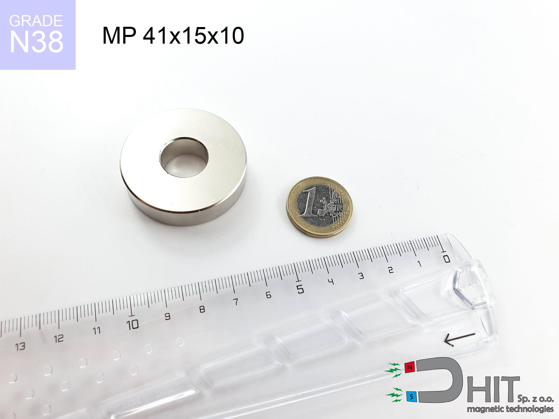
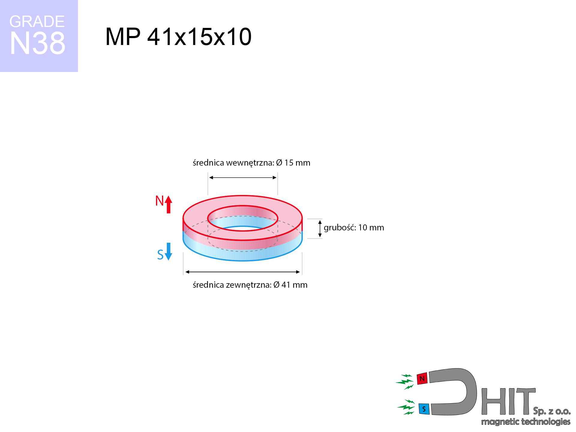
MP 41x15x10 / N38 - ring magnet
ring magnet
Catalog no 030200
GTIN/EAN: 5906301812173
Diameter
41 mm [±0,1 mm]
internal diameter Ø
15 mm [±0,1 mm]
Height
10 mm [±0,1 mm]
Weight
85.77 g
Magnetization Direction
↑ axial
Load capacity
24.44 kg / 239.78 N
Magnetic Induction
271.77 mT / 2718 Gs
Coating
[NiCuNi] Nickel
50.00 ZŁ with VAT / pcs + price for transport
40.65 ZŁ net + 23% VAT / pcs
bulk discounts:
Need more?Engineering report for this magnet
Full PDF analysis: pull and shear force, effect of distance, temperature and plate thickness, safety distances and the demagnetization curve.
Give us a call
+48 888 99 98 98
alternatively let us know via
inquiry form
the contact section.
Weight along with appearance of magnets can be tested on our
magnetic mass calculator.
Orders placed before 14:00 will be shipped the same business day.
Detailed specification - MP 41x15x10 / N38 - ring magnet
Specification / characteristics - MP 41x15x10 / N38 - ring magnet
| properties | values |
|---|---|
| Cat. no. | 030200 |
| GTIN/EAN | 5906301812173 |
| Production/Distribution | Dhit sp. z o.o. |
| Country of origin | Poland / China / Germany |
| Customs code | 85059029 |
| Diameter | 41 mm [±0,1 mm] |
| internal diameter Ø | 15 mm [±0,1 mm] |
| Height | 10 mm [±0,1 mm] |
| Weight | 85.77 g |
| Magnetization Direction | ↑ axial |
| Load capacity ~ ? | 24.44 kg / 239.78 N |
| Magnetic Induction ~ ? | 271.77 mT / 2718 Gs |
| Coating | [NiCuNi] Nickel |
| Manufacturing Tolerance | ±0.1 mm |
Magnetic properties of material N38
| properties | values | units |
|---|---|---|
| remenance Br [min. - max.] ? | 12.2-12.6 | kGs |
| remenance Br [min. - max.] ? | 1220-1260 | mT |
| coercivity bHc ? | 10.8-11.5 | kOe |
| coercivity bHc ? | 860-915 | kA/m |
| actual internal force iHc | ≥ 12 | kOe |
| actual internal force iHc | ≥ 955 | kA/m |
| energy density [min. - max.] ? | 36-38 | BH max MGOe |
| energy density [min. - max.] ? | 287-303 | BH max KJ/m |
| max. temperature ? | ≤ 80 | °C |
Physical properties of sintered neodymium magnets Nd2Fe14B at 20°C
| properties | values | units |
|---|---|---|
| Vickers hardness | ≥550 | Hv |
| Density | ≥7.4 | g/cm3 |
| Curie Temperature TC | 312 - 380 | °C |
| Curie Temperature TF | 593 - 716 | °F |
| Specific resistance | 150 | μΩ⋅cm |
| Bending strength | 250 | MPa |
| Compressive strength | 1000~1100 | MPa |
| Thermal expansion parallel (∥) to orientation (M) | (3-4) x 10-6 | °C-1 |
| Thermal expansion perpendicular (⊥) to orientation (M) | -(1-3) x 10-6 | °C-1 |
| Young's modulus | 1.7 x 10⁴ | kg/mm² |
Physical modeling of the product - technical parameters
The following values represent the direct effect of a mathematical calculation. Values are based on algorithms for the class Nd2Fe14B. Real-world parameters may differ. Use these calculations as a supplementary guide when designing systems.
Table 1: Static force (pull vs gap) - power drop
MP 41x15x10 / N38
| Distance (mm) | Induction (Gauss) / mT | Pull Force (kg/lbs/g/N) | Risk Status |
|---|---|---|---|
| 0 mm |
5232 Gs
523.2 mT
|
24.44 kg / 53.88 LBS
24440.0 g / 239.8 N
|
dangerous! |
| 1 mm |
4978 Gs
497.8 mT
|
22.12 kg / 48.77 LBS
22120.4 g / 217.0 N
|
dangerous! |
| 2 mm |
4720 Gs
472.0 mT
|
19.89 kg / 43.85 LBS
19888.8 g / 195.1 N
|
dangerous! |
| 3 mm |
4464 Gs
446.4 mT
|
17.79 kg / 39.22 LBS
17788.4 g / 174.5 N
|
dangerous! |
| 5 mm |
3964 Gs
396.4 mT
|
14.03 kg / 30.93 LBS
14030.8 g / 137.6 N
|
dangerous! |
| 10 mm |
2861 Gs
286.1 mT
|
7.31 kg / 16.11 LBS
7308.1 g / 71.7 N
|
strong |
| 15 mm |
2028 Gs
202.8 mT
|
3.67 kg / 8.09 LBS
3670.1 g / 36.0 N
|
strong |
| 20 mm |
1443 Gs
144.3 mT
|
1.86 kg / 4.10 LBS
1858.4 g / 18.2 N
|
weak grip |
| 30 mm |
770 Gs
77.0 mT
|
0.53 kg / 1.17 LBS
529.8 g / 5.2 N
|
weak grip |
| 50 mm |
280 Gs
28.0 mT
|
0.07 kg / 0.15 LBS
69.8 g / 0.7 N
|
weak grip |
Table 2: Shear capacity (wall)
MP 41x15x10 / N38
| Distance (mm) | Friction coefficient | Pull Force (kg/lbs/g/N) |
|---|---|---|
| 0 mm | Stal (~0.2) |
4.89 kg / 10.78 LBS
4888.0 g / 48.0 N
|
| 1 mm | Stal (~0.2) |
4.42 kg / 9.75 LBS
4424.0 g / 43.4 N
|
| 2 mm | Stal (~0.2) |
3.98 kg / 8.77 LBS
3978.0 g / 39.0 N
|
| 3 mm | Stal (~0.2) |
3.56 kg / 7.84 LBS
3558.0 g / 34.9 N
|
| 5 mm | Stal (~0.2) |
2.81 kg / 6.19 LBS
2806.0 g / 27.5 N
|
| 10 mm | Stal (~0.2) |
1.46 kg / 3.22 LBS
1462.0 g / 14.3 N
|
| 15 mm | Stal (~0.2) |
0.73 kg / 1.62 LBS
734.0 g / 7.2 N
|
| 20 mm | Stal (~0.2) |
0.37 kg / 0.82 LBS
372.0 g / 3.6 N
|
| 30 mm | Stal (~0.2) |
0.11 kg / 0.23 LBS
106.0 g / 1.0 N
|
| 50 mm | Stal (~0.2) |
0.01 kg / 0.03 LBS
14.0 g / 0.1 N
|
Table 3: Wall mounting (sliding) - behavior on slippery surfaces
MP 41x15x10 / N38
| Surface type | Friction coefficient / % Mocy | Max load (kg/lbs/g/N) |
|---|---|---|
| Raw steel |
µ = 0.3
30% Nominalnej Siły
|
7.33 kg / 16.16 LBS
7332.0 g / 71.9 N
|
| Painted steel (standard) |
µ = 0.2
20% Nominalnej Siły
|
4.89 kg / 10.78 LBS
4888.0 g / 48.0 N
|
| Oily/slippery steel |
µ = 0.1
10% Nominalnej Siły
|
2.44 kg / 5.39 LBS
2444.0 g / 24.0 N
|
| Magnet with anti-slip rubber |
µ = 0.5
50% Nominalnej Siły
|
12.22 kg / 26.94 LBS
12220.0 g / 119.9 N
|
Table 4: Material efficiency (substrate influence) - sheet metal selection
MP 41x15x10 / N38
| Steel thickness (mm) | % power | Real pull force (kg/lbs/g/N) |
|---|---|---|
| 0.5 mm |
|
1.22 kg / 2.69 LBS
1222.0 g / 12.0 N
|
| 1 mm |
|
3.06 kg / 6.74 LBS
3055.0 g / 30.0 N
|
| 2 mm |
|
6.11 kg / 13.47 LBS
6110.0 g / 59.9 N
|
| 3 mm |
|
9.17 kg / 20.21 LBS
9165.0 g / 89.9 N
|
| 5 mm |
|
15.28 kg / 33.68 LBS
15275.0 g / 149.8 N
|
| 10 mm |
|
24.44 kg / 53.88 LBS
24440.0 g / 239.8 N
|
| 11 mm |
|
24.44 kg / 53.88 LBS
24440.0 g / 239.8 N
|
| 12 mm |
|
24.44 kg / 53.88 LBS
24440.0 g / 239.8 N
|
Table 5: Working in heat (stability) - power drop
MP 41x15x10 / N38
| Ambient temp. (°C) | Power loss | Remaining pull (kg/lbs/g/N) | Status |
|---|---|---|---|
| 20 °C | 0.0% |
24.44 kg / 53.88 LBS
24440.0 g / 239.8 N
|
OK |
| 40 °C | -2.2% |
23.90 kg / 52.70 LBS
23902.3 g / 234.5 N
|
OK |
| 60 °C | -4.4% |
23.36 kg / 51.51 LBS
23364.6 g / 229.2 N
|
OK |
| 80 °C | -6.6% |
22.83 kg / 50.32 LBS
22827.0 g / 223.9 N
|
|
| 100 °C | -28.8% |
17.40 kg / 38.36 LBS
17401.3 g / 170.7 N
|
Table 6: Two magnets (repulsion) - field collision
MP 41x15x10 / N38
| Gap (mm) | Attraction (kg/lbs) (N-S) | Sliding Force (kg/lbs/g/N) | Repulsion (kg/lbs) (N-N) |
|---|---|---|---|
| 0 mm |
178.13 kg / 392.71 LBS
5 907 Gs
|
26.72 kg / 58.91 LBS
26719 g / 262.1 N
|
N/A |
| 1 mm |
169.67 kg / 374.06 LBS
10 213 Gs
|
25.45 kg / 56.11 LBS
25451 g / 249.7 N
|
152.70 kg / 336.65 LBS
~0 Gs
|
| 2 mm |
161.22 kg / 355.43 LBS
9 955 Gs
|
24.18 kg / 53.32 LBS
24183 g / 237.2 N
|
145.10 kg / 319.89 LBS
~0 Gs
|
| 3 mm |
152.98 kg / 337.26 LBS
9 697 Gs
|
22.95 kg / 50.59 LBS
22947 g / 225.1 N
|
137.68 kg / 303.53 LBS
~0 Gs
|
| 5 mm |
137.18 kg / 302.42 LBS
9 183 Gs
|
20.58 kg / 45.36 LBS
20577 g / 201.9 N
|
123.46 kg / 272.18 LBS
~0 Gs
|
| 10 mm |
102.26 kg / 225.45 LBS
7 929 Gs
|
15.34 kg / 33.82 LBS
15339 g / 150.5 N
|
92.04 kg / 202.90 LBS
~0 Gs
|
| 20 mm |
53.26 kg / 117.43 LBS
5 722 Gs
|
7.99 kg / 17.61 LBS
7990 g / 78.4 N
|
47.94 kg / 105.69 LBS
~0 Gs
|
| 50 mm |
7.08 kg / 15.62 LBS
2 087 Gs
|
1.06 kg / 2.34 LBS
1063 g / 10.4 N
|
6.38 kg / 14.06 LBS
~0 Gs
|
| 60 mm |
3.86 kg / 8.51 LBS
1 541 Gs
|
0.58 kg / 1.28 LBS
579 g / 5.7 N
|
3.48 kg / 7.66 LBS
~0 Gs
|
| 70 mm |
2.20 kg / 4.84 LBS
1 162 Gs
|
0.33 kg / 0.73 LBS
330 g / 3.2 N
|
1.98 kg / 4.36 LBS
~0 Gs
|
| 80 mm |
1.30 kg / 2.87 LBS
895 Gs
|
0.20 kg / 0.43 LBS
195 g / 1.9 N
|
1.17 kg / 2.58 LBS
~0 Gs
|
| 90 mm |
0.80 kg / 1.76 LBS
701 Gs
|
0.12 kg / 0.26 LBS
120 g / 1.2 N
|
0.72 kg / 1.59 LBS
~0 Gs
|
| 100 mm |
0.51 kg / 1.12 LBS
559 Gs
|
0.08 kg / 0.17 LBS
76 g / 0.7 N
|
0.46 kg / 1.01 LBS
~0 Gs
|
Table 7: Safety (HSE) (implants) - warnings
MP 41x15x10 / N38
| Object / Device | Limit (Gauss) / mT | Safe distance |
|---|---|---|
| Pacemaker | 5 Gs (0.5 mT) | 24.0 cm |
| Hearing aid | 10 Gs (1.0 mT) | 19.0 cm |
| Mechanical watch | 20 Gs (2.0 mT) | 15.0 cm |
| Phone / Smartphone | 40 Gs (4.0 mT) | 11.5 cm |
| Remote | 50 Gs (5.0 mT) | 10.5 cm |
| Payment card | 400 Gs (40.0 mT) | 4.5 cm |
| HDD hard drive | 600 Gs (60.0 mT) | 3.5 cm |
Table 8: Collisions (kinetic energy) - warning
MP 41x15x10 / N38
| Start from (mm) | Speed (km/h) | Energy (J) | Predicted outcome |
|---|---|---|---|
| 10 mm |
19.95 km/h
(5.54 m/s)
|
1.32 J | |
| 30 mm |
29.88 km/h
(8.30 m/s)
|
2.96 J | |
| 50 mm |
38.13 km/h
(10.59 m/s)
|
4.81 J | |
| 100 mm |
53.84 km/h
(14.96 m/s)
|
9.59 J |
Table 9: Corrosion resistance
MP 41x15x10 / N38
| Technical parameter | Value / Description |
|---|---|
| Coating type | [NiCuNi] Nickel |
| Layer structure | Nickel - Copper - Nickel |
| Layer thickness | 10-20 µm |
| Salt spray test (SST) ? | 24 h |
| Recommended environment | Indoors only (dry) |
Table 10: Construction data (Pc)
MP 41x15x10 / N38
| Parameter | Value | SI Unit / Description |
|---|---|---|
| Magnetic Flux | 56 505 Mx | 565.0 µWb |
| Pc Coefficient | 0.80 | High (Stable) |
Table 11: Hydrostatics and buoyancy
MP 41x15x10 / N38
| Environment | Effective steel pull | Effect |
|---|---|---|
| Air (land) | 24.44 kg | Standard |
| Water (riverbed) |
27.98 kg
(+3.54 kg buoyancy gain)
|
+14.5% |
1. Sliding resistance
*Warning: On a vertical wall, the magnet holds merely ~20% of its nominal pull.
2. Plate thickness effect
*Thin metal sheet (e.g. 0.5mm PC case) drastically reduces the holding force.
3. Thermal stability
*For standard magnets, the max working temp is 80°C.
4. Demagnetization curve and operating point (B-H)
chart generated for the permeance coefficient Pc (Permeance Coefficient) = 0.80
This simulation demonstrates the magnetic stability of the selected magnet under specific geometric conditions. The solid red line represents the demagnetization curve (material potential), while the dashed blue line is the load line based on the magnet's geometry. The Pc (Permeance Coefficient), also known as the load line slope, is a dimensionless value that describes the relationship between the magnet's shape and its magnetic stability. The intersection of these two lines (the black dot) is the operating point — it determines the actual magnetic flux density generated by the magnet in this specific configuration. A higher Pc value means the magnet is more 'slender' (tall relative to its area), resulting in a higher operating point and better resistance to irreversible demagnetization caused by external fields or temperature. A value of 0.42 is relatively low (typical for flat magnets), meaning the operating point is closer to the 'knee' of the curve — caution is advised when operating at temperatures near the maximum limit to avoid strength loss.
Material specification
| iron (Fe) | 64% – 68% |
| neodymium (Nd) | 29% – 32% |
| boron (B) | 1.1% – 1.2% |
| dysprosium (Dy) | 0.5% – 2.0% |
| coating (Ni-Cu-Ni) | < 0.05% |
Sustainability
| recyclability (EoL) | 100% |
| recycled raw materials | ~10% (pre-cons) |
| carbon footprint | low / zredukowany |
| waste code (EWC) | 16 02 16 |
See more offers


Pros as well as cons of rare earth magnets.
Benefits
- Their strength is durable, and after approximately ten years it decreases only by ~1% (theoretically),
- They maintain their magnetic properties even under strong external field,
- A magnet with a metallic nickel surface looks better,
- Neodymium magnets achieve maximum magnetic induction on a small area, which allows for strong attraction,
- Made from properly selected components, these magnets show impressive resistance to high heat, enabling them to function (depending on their shape) at temperatures up to 230°C and above...
- Thanks to modularity in constructing and the capacity to adapt to individual projects,
- Significant place in future technologies – they are used in mass storage devices, electric motors, precision medical tools, and industrial machines.
- Compactness – despite small sizes they provide effective action, making them ideal for precision applications
Cons
- At strong impacts they can crack, therefore we recommend placing them in steel cases. A metal housing provides additional protection against damage and increases the magnet's durability.
- When exposed to high temperature, neodymium magnets suffer a drop in force. Often, when the temperature exceeds 80°C, their strength decreases (depending on the size, as well as shape of the magnet). For those who need magnets for extreme conditions, we offer [AH] versions withstanding up to 230°C
- Due to the susceptibility of magnets to corrosion in a humid environment, we recommend using waterproof magnets made of rubber, plastic or other material immune to moisture, when using outdoors
- Due to limitations in creating threads and complicated forms in magnets, we propose using cover - magnetic mount.
- Potential hazard related to microscopic parts of magnets are risky, in case of ingestion, which is particularly important in the context of child health protection. It is also worth noting that small components of these magnets are able to be problematic in diagnostics medical in case of swallowing.
- Due to complex production process, their price is relatively high,
Holding force characteristics
Maximum lifting capacity of the magnet – what it depends on?
- with the application of a sheet made of special test steel, guaranteeing full magnetic saturation
- whose transverse dimension is min. 10 mm
- with a plane cleaned and smooth
- under conditions of gap-free contact (metal-to-metal)
- during pulling in a direction perpendicular to the plane
- at temperature approx. 20 degrees Celsius
What influences lifting capacity in practice
- Space between magnet and steel – every millimeter of separation (caused e.g. by varnish or unevenness) significantly weakens the magnet efficiency, often by half at just 0.5 mm.
- Angle of force application – highest force is available only during perpendicular pulling. The force required to slide of the magnet along the surface is typically several times smaller (approx. 1/5 of the lifting capacity).
- Element thickness – to utilize 100% power, the steel must be adequately massive. Thin sheet restricts the attraction force (the magnet "punches through" it).
- Steel type – mild steel attracts best. Alloy admixtures decrease magnetic permeability and lifting capacity.
- Smoothness – ideal contact is obtained only on polished steel. Rough texture create air cushions, weakening the magnet.
- Temperature influence – high temperature weakens magnetic field. Too high temperature can permanently demagnetize the magnet.
Lifting capacity testing was conducted on a smooth plate of optimal thickness, under a perpendicular pulling force, however under parallel forces the lifting capacity is smaller. In addition, even a small distance between the magnet’s surface and the plate lowers the holding force.
Warnings
Heat warning
Control the heat. Exposing the magnet above 80 degrees Celsius will permanently weaken its magnetic structure and strength.
Flammability
Powder generated during machining of magnets is combustible. Avoid drilling into magnets unless you are an expert.
No play value
Absolutely keep magnets out of reach of children. Ingestion danger is significant, and the effects of magnets clamping inside the body are fatal.
Bodily injuries
Large magnets can break fingers instantly. Never put your hand betwixt two strong magnets.
Skin irritation risks
Studies show that the nickel plating (the usual finish) is a potent allergen. If your skin reacts to metals, prevent direct skin contact and choose encased magnets.
GPS Danger
Remember: rare earth magnets produce a field that confuses sensitive sensors. Keep a safe distance from your phone, device, and navigation systems.
Handling rules
Before use, read the rules. Uncontrolled attraction can destroy the magnet or hurt your hand. Be predictive.
Magnetic media
Intense magnetic fields can destroy records on payment cards, HDDs, and storage devices. Keep a distance of at least 10 cm.
Medical interference
For implant holders: Powerful magnets affect electronics. Maintain at least 30 cm distance or request help to handle the magnets.
Magnet fragility
NdFeB magnets are sintered ceramics, meaning they are prone to chipping. Clashing of two magnets leads to them shattering into small pieces.
Tabela kosztu i czasu dostawy
Płatność przed wysyłką:

GLS kurier
Przesyłka będzie u Ciebie za 2-3 dni
14.99 ZŁ

InPost Paczkomaty 24/7
Przesyłka będzie u Ciebie za 1-2 dni
12.30 ZŁ
Płatność przy odbiorze (pobranie):
GLS kurier
Przesyłka będzie u Ciebie za 1-2 dni
23.00 ZŁ
Rate the product
Your rating