

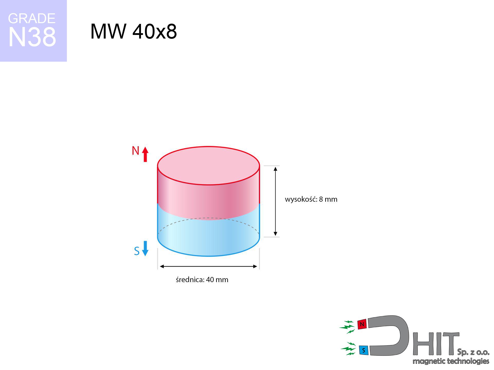
MW 40x8 / N38 - cylindrical magnet
cylindrical magnet
Catalog no 010069
GTIN/EAN: 5906301810681
Diameter Ø
40 mm [±0,1 mm]
Height
8 mm [±0,1 mm]
Weight
75.4 g
Magnetization Direction
↑ axial
Load capacity
20.43 kg / 200.39 N
Magnetic Induction
230.22 mT / 2302 Gs
Coating
[NiCuNi] Nickel
31.27 ZŁ with VAT / pcs + price for transport
25.42 ZŁ net + 23% VAT / pcs
bulk discounts:
Need more?
Contact us by phone
+48 888 99 98 98
or contact us using
request form
the contact form page.
Strength and shape of a neodymium magnet can be checked using our
online calculation tool.
Same-day processing for orders placed before 14:00.
Technical data of the product - MW 40x8 / N38 - cylindrical magnet
Specification / characteristics - MW 40x8 / N38 - cylindrical magnet
| properties | values |
|---|---|
| Cat. no. | 010069 |
| GTIN/EAN | 5906301810681 |
| Production/Distribution | Dhit sp. z o.o. |
| Country of origin | Poland / China / Germany |
| Customs code | 85059029 |
| Diameter Ø | 40 mm [±0,1 mm] |
| Height | 8 mm [±0,1 mm] |
| Weight | 75.4 g |
| Magnetization Direction | ↑ axial |
| Load capacity ~ ? | 20.43 kg / 200.39 N |
| Magnetic Induction ~ ? | 230.22 mT / 2302 Gs |
| Coating | [NiCuNi] Nickel |
| Manufacturing Tolerance | ±0.1 mm |
Magnetic properties of material N38
| properties | values | units |
|---|---|---|
| remenance Br [min. - max.] ? | 12.2-12.6 | kGs |
| remenance Br [min. - max.] ? | 1220-1260 | mT |
| coercivity bHc ? | 10.8-11.5 | kOe |
| coercivity bHc ? | 860-915 | kA/m |
| actual internal force iHc | ≥ 12 | kOe |
| actual internal force iHc | ≥ 955 | kA/m |
| energy density [min. - max.] ? | 36-38 | BH max MGOe |
| energy density [min. - max.] ? | 287-303 | BH max KJ/m |
| max. temperature ? | ≤ 80 | °C |
Physical properties of sintered neodymium magnets Nd2Fe14B at 20°C
| properties | values | units |
|---|---|---|
| Vickers hardness | ≥550 | Hv |
| Density | ≥7.4 | g/cm3 |
| Curie Temperature TC | 312 - 380 | °C |
| Curie Temperature TF | 593 - 716 | °F |
| Specific resistance | 150 | μΩ⋅cm |
| Bending strength | 250 | MPa |
| Compressive strength | 1000~1100 | MPa |
| Thermal expansion parallel (∥) to orientation (M) | (3-4) x 10-6 | °C-1 |
| Thermal expansion perpendicular (⊥) to orientation (M) | -(1-3) x 10-6 | °C-1 |
| Young's modulus | 1.7 x 10⁴ | kg/mm² |
Technical modeling of the assembly - report
Presented information are the outcome of a physical simulation. Values are based on algorithms for the material Nd2Fe14B. Real-world conditions may differ from theoretical values. Please consider these data as a reference point during assembly planning.
Table 1: Static pull force (force vs distance) - characteristics
MW 40x8 / N38
| Distance (mm) | Induction (Gauss) / mT | Pull Force (kg/lbs/g/N) | Risk Status |
|---|---|---|---|
| 0 mm |
2302 Gs
230.2 mT
|
20.43 kg / 45.04 lbs
20430.0 g / 200.4 N
|
dangerous! |
| 1 mm |
2235 Gs
223.5 mT
|
19.25 kg / 42.44 lbs
19252.0 g / 188.9 N
|
dangerous! |
| 2 mm |
2156 Gs
215.6 mT
|
17.92 kg / 39.50 lbs
17917.4 g / 175.8 N
|
dangerous! |
| 3 mm |
2068 Gs
206.8 mT
|
16.49 kg / 36.36 lbs
16490.6 g / 161.8 N
|
dangerous! |
| 5 mm |
1875 Gs
187.5 mT
|
13.56 kg / 29.89 lbs
13556.7 g / 133.0 N
|
dangerous! |
| 10 mm |
1375 Gs
137.5 mT
|
7.29 kg / 16.07 lbs
7287.4 g / 71.5 N
|
medium risk |
| 15 mm |
959 Gs
95.9 mT
|
3.54 kg / 7.81 lbs
3542.3 g / 34.8 N
|
medium risk |
| 20 mm |
661 Gs
66.1 mT
|
1.68 kg / 3.71 lbs
1684.9 g / 16.5 N
|
safe |
| 30 mm |
328 Gs
32.8 mT
|
0.41 kg / 0.91 lbs
414.2 g / 4.1 N
|
safe |
| 50 mm |
105 Gs
10.5 mT
|
0.04 kg / 0.09 lbs
42.3 g / 0.4 N
|
safe |
Table 2: Sliding load (wall)
MW 40x8 / N38
| Distance (mm) | Friction coefficient | Pull Force (kg/lbs/g/N) |
|---|---|---|
| 0 mm | Stal (~0.2) |
4.09 kg / 9.01 lbs
4086.0 g / 40.1 N
|
| 1 mm | Stal (~0.2) |
3.85 kg / 8.49 lbs
3850.0 g / 37.8 N
|
| 2 mm | Stal (~0.2) |
3.58 kg / 7.90 lbs
3584.0 g / 35.2 N
|
| 3 mm | Stal (~0.2) |
3.30 kg / 7.27 lbs
3298.0 g / 32.4 N
|
| 5 mm | Stal (~0.2) |
2.71 kg / 5.98 lbs
2712.0 g / 26.6 N
|
| 10 mm | Stal (~0.2) |
1.46 kg / 3.21 lbs
1458.0 g / 14.3 N
|
| 15 mm | Stal (~0.2) |
0.71 kg / 1.56 lbs
708.0 g / 6.9 N
|
| 20 mm | Stal (~0.2) |
0.34 kg / 0.74 lbs
336.0 g / 3.3 N
|
| 30 mm | Stal (~0.2) |
0.08 kg / 0.18 lbs
82.0 g / 0.8 N
|
| 50 mm | Stal (~0.2) |
0.01 kg / 0.02 lbs
8.0 g / 0.1 N
|
Table 3: Vertical assembly (shearing) - behavior on slippery surfaces
MW 40x8 / N38
| Surface type | Friction coefficient / % Mocy | Max load (kg/lbs/g/N) |
|---|---|---|
| Raw steel |
µ = 0.3
30% Nominalnej Siły
|
6.13 kg / 13.51 lbs
6129.0 g / 60.1 N
|
| Painted steel (standard) |
µ = 0.2
20% Nominalnej Siły
|
4.09 kg / 9.01 lbs
4086.0 g / 40.1 N
|
| Oily/slippery steel |
µ = 0.1
10% Nominalnej Siły
|
2.04 kg / 4.50 lbs
2043.0 g / 20.0 N
|
| Magnet with anti-slip rubber |
µ = 0.5
50% Nominalnej Siły
|
10.22 kg / 22.52 lbs
10215.0 g / 100.2 N
|
Table 4: Material efficiency (saturation) - power losses
MW 40x8 / N38
| Steel thickness (mm) | % power | Real pull force (kg/lbs/g/N) |
|---|---|---|
| 0.5 mm |
|
1.02 kg / 2.25 lbs
1021.5 g / 10.0 N
|
| 1 mm |
|
2.55 kg / 5.63 lbs
2553.8 g / 25.1 N
|
| 2 mm |
|
5.11 kg / 11.26 lbs
5107.5 g / 50.1 N
|
| 3 mm |
|
7.66 kg / 16.89 lbs
7661.3 g / 75.2 N
|
| 5 mm |
|
12.77 kg / 28.15 lbs
12768.8 g / 125.3 N
|
| 10 mm |
|
20.43 kg / 45.04 lbs
20430.0 g / 200.4 N
|
| 11 mm |
|
20.43 kg / 45.04 lbs
20430.0 g / 200.4 N
|
| 12 mm |
|
20.43 kg / 45.04 lbs
20430.0 g / 200.4 N
|
Table 5: Working in heat (stability) - thermal limit
MW 40x8 / N38
| Ambient temp. (°C) | Power loss | Remaining pull (kg/lbs/g/N) | Status |
|---|---|---|---|
| 20 °C | 0.0% |
20.43 kg / 45.04 lbs
20430.0 g / 200.4 N
|
OK |
| 40 °C | -2.2% |
19.98 kg / 44.05 lbs
19980.5 g / 196.0 N
|
OK |
| 60 °C | -4.4% |
19.53 kg / 43.06 lbs
19531.1 g / 191.6 N
|
|
| 80 °C | -6.6% |
19.08 kg / 42.07 lbs
19081.6 g / 187.2 N
|
|
| 100 °C | -28.8% |
14.55 kg / 32.07 lbs
14546.2 g / 142.7 N
|
Table 6: Two magnets (attraction) - field range
MW 40x8 / N38
| Gap (mm) | Attraction (kg/lbs) (N-S) | Shear Strength (kg/lbs/g/N) | Repulsion (kg/lbs) (N-N) |
|---|---|---|---|
| 0 mm |
41.05 kg / 90.51 lbs
3 871 Gs
|
6.16 kg / 13.58 lbs
6158 g / 60.4 N
|
N/A |
| 1 mm |
39.92 kg / 88.02 lbs
4 540 Gs
|
5.99 kg / 13.20 lbs
5989 g / 58.7 N
|
35.93 kg / 79.22 lbs
~0 Gs
|
| 2 mm |
38.69 kg / 85.29 lbs
4 469 Gs
|
5.80 kg / 12.79 lbs
5803 g / 56.9 N
|
34.82 kg / 76.76 lbs
~0 Gs
|
| 3 mm |
37.38 kg / 82.40 lbs
4 393 Gs
|
5.61 kg / 12.36 lbs
5606 g / 55.0 N
|
33.64 kg / 74.16 lbs
~0 Gs
|
| 5 mm |
34.59 kg / 76.25 lbs
4 226 Gs
|
5.19 kg / 11.44 lbs
5188 g / 50.9 N
|
31.13 kg / 68.63 lbs
~0 Gs
|
| 10 mm |
27.24 kg / 60.06 lbs
3 750 Gs
|
4.09 kg / 9.01 lbs
4086 g / 40.1 N
|
24.52 kg / 54.05 lbs
~0 Gs
|
| 20 mm |
14.64 kg / 32.28 lbs
2 750 Gs
|
2.20 kg / 4.84 lbs
2197 g / 21.5 N
|
13.18 kg / 29.06 lbs
~0 Gs
|
| 50 mm |
1.65 kg / 3.63 lbs
922 Gs
|
0.25 kg / 0.54 lbs
247 g / 2.4 N
|
1.48 kg / 3.26 lbs
~0 Gs
|
| 60 mm |
0.83 kg / 1.84 lbs
656 Gs
|
0.12 kg / 0.28 lbs
125 g / 1.2 N
|
0.75 kg / 1.65 lbs
~0 Gs
|
| 70 mm |
0.44 kg / 0.97 lbs
477 Gs
|
0.07 kg / 0.15 lbs
66 g / 0.6 N
|
0.40 kg / 0.87 lbs
~0 Gs
|
| 80 mm |
0.24 kg / 0.54 lbs
355 Gs
|
0.04 kg / 0.08 lbs
37 g / 0.4 N
|
0.22 kg / 0.49 lbs
~0 Gs
|
| 90 mm |
0.14 kg / 0.31 lbs
270 Gs
|
0.02 kg / 0.05 lbs
21 g / 0.2 N
|
0.13 kg / 0.28 lbs
~0 Gs
|
| 100 mm |
0.09 kg / 0.19 lbs
210 Gs
|
0.01 kg / 0.03 lbs
13 g / 0.1 N
|
0.08 kg / 0.17 lbs
~0 Gs
|
Table 7: Hazards (electronics) - warnings
MW 40x8 / N38
| Object / Device | Limit (Gauss) / mT | Safe distance |
|---|---|---|
| Pacemaker | 5 Gs (0.5 mT) | 15.5 cm |
| Hearing aid | 10 Gs (1.0 mT) | 12.5 cm |
| Mechanical watch | 20 Gs (2.0 mT) | 9.5 cm |
| Phone / Smartphone | 40 Gs (4.0 mT) | 7.5 cm |
| Remote | 50 Gs (5.0 mT) | 7.0 cm |
| Payment card | 400 Gs (40.0 mT) | 3.0 cm |
| HDD hard drive | 600 Gs (60.0 mT) | 2.5 cm |
Table 8: Dynamics (kinetic energy) - warning
MW 40x8 / N38
| Start from (mm) | Speed (km/h) | Energy (J) | Predicted outcome |
|---|---|---|---|
| 10 mm |
19.96 km/h
(5.54 m/s)
|
1.16 J | |
| 30 mm |
29.12 km/h
(8.09 m/s)
|
2.47 J | |
| 50 mm |
37.17 km/h
(10.32 m/s)
|
4.02 J | |
| 100 mm |
52.50 km/h
(14.58 m/s)
|
8.02 J |
Table 9: Anti-corrosion coating durability
MW 40x8 / N38
| Technical parameter | Value / Description |
|---|---|
| Coating type | [NiCuNi] Nickel |
| Layer structure | Nickel - Copper - Nickel |
| Layer thickness | 10-20 µm |
| Salt spray test (SST) ? | 24 h |
| Recommended environment | Indoors only (dry) |
Table 10: Construction data (Flux)
MW 40x8 / N38
| Parameter | Value | SI Unit / Description |
|---|---|---|
| Magnetic Flux | 33 553 Mx | 335.5 µWb |
| Pc Coefficient | 0.29 | Low (Flat) |
Table 11: Physics of underwater searching
MW 40x8 / N38
| Environment | Effective steel pull | Effect |
|---|---|---|
| Air (land) | 20.43 kg | Standard |
| Water (riverbed) |
23.39 kg
(+2.96 kg buoyancy gain)
|
+14.5% |
1. Wall mount (shear)
*Caution: On a vertical wall, the magnet retains only a fraction of its nominal pull.
2. Steel saturation
*Thin steel (e.g. 0.5mm PC case) drastically limits the holding force.
3. Heat tolerance
*For N38 grade, the critical limit is 80°C.
4. Demagnetization curve and operating point (B-H)
chart generated for the permeance coefficient Pc (Permeance Coefficient) = 0.29
The chart above illustrates the magnetic characteristics of the material within the second quadrant of the hysteresis loop. The solid red line represents the demagnetization curve (material potential), while the dashed blue line is the load line based on the magnet's geometry. The Pc (Permeance Coefficient), also known as the load line slope, is a dimensionless value that describes the relationship between the magnet's shape and its magnetic stability. The intersection of these two lines (the black dot) is the operating point — it determines the actual magnetic flux density generated by the magnet in this specific configuration. A higher Pc value means the magnet is more 'slender' (tall relative to its area), resulting in a higher operating point and better resistance to irreversible demagnetization caused by external fields or temperature. A value of 0.42 is relatively low (typical for flat magnets), meaning the operating point is closer to the 'knee' of the curve — caution is advised when operating at temperatures near the maximum limit to avoid strength loss.
Elemental analysis
| iron (Fe) | 64% – 68% |
| neodymium (Nd) | 29% – 32% |
| boron (B) | 1.1% – 1.2% |
| dysprosium (Dy) | 0.5% – 2.0% |
| coating (Ni-Cu-Ni) | < 0.05% |
Sustainability
| recyclability (EoL) | 100% |
| recycled raw materials | ~10% (pre-cons) |
| carbon footprint | low / zredukowany |
| waste code (EWC) | 16 02 16 |
Other deals


![UMGGZ 88x8.5 [M8] GZ / N38 - rubber magnetic holder external thread](https://cdn3.dhit.pl/graphics/products/umg-88x8.5-m8-gz-waf.jpg "UMGGZ 88x8.5 [M8] GZ / N38 - rubber magnetic holder external thread")
Advantages as well as disadvantages of neodymium magnets.
Advantages
- They virtually do not lose strength, because even after 10 years the decline in efficiency is only ~1% (based on calculations),
- They show high resistance to demagnetization induced by external field influence,
- A magnet with a shiny silver surface is more attractive,
- Magnets possess huge magnetic induction on the working surface,
- Thanks to resistance to high temperature, they are able to function (depending on the shape) even at temperatures up to 230°C and higher...
- Considering the potential of accurate molding and adaptation to specialized needs, NdFeB magnets can be produced in a wide range of shapes and sizes, which increases their versatility,
- Versatile presence in advanced technology sectors – they are used in computer drives, electromotive mechanisms, diagnostic systems, and technologically advanced constructions.
- Relatively small size with high pulling force – neodymium magnets offer strong magnetic field in compact dimensions, which makes them useful in compact constructions
Limitations
- To avoid cracks upon strong impacts, we suggest using special steel housings. Such a solution protects the magnet and simultaneously increases its durability.
- Neodymium magnets demagnetize when exposed to high temperatures. After reaching 80°C, many of them experience permanent drop of power (a factor is the shape as well as dimensions of the magnet). We offer magnets specially adapted to work at temperatures up to 230°C marked [AH], which are extremely resistant to heat
- Magnets exposed to a humid environment can corrode. Therefore during using outdoors, we advise using waterproof magnets made of rubber, plastic or other material protecting against moisture
- Due to limitations in creating threads and complex forms in magnets, we recommend using cover - magnetic holder.
- Possible danger related to microscopic parts of magnets are risky, in case of ingestion, which is particularly important in the aspect of protecting the youngest. It is also worth noting that small elements of these devices can be problematic in diagnostics medical in case of swallowing.
- High unit price – neodymium magnets have a higher price than other types of magnets (e.g. ferrite), which hinders application in large quantities
Holding force characteristics
Highest magnetic holding force – what affects it?
- on a block made of structural steel, perfectly concentrating the magnetic flux
- whose transverse dimension is min. 10 mm
- characterized by even structure
- with direct contact (no impurities)
- under vertical force vector (90-degree angle)
- at ambient temperature approx. 20 degrees Celsius
Determinants of lifting force in real conditions
- Gap (betwixt the magnet and the metal), as even a microscopic clearance (e.g. 0.5 mm) leads to a drastic drop in lifting capacity by up to 50% (this also applies to varnish, corrosion or dirt).
- Force direction – remember that the magnet has greatest strength perpendicularly. Under shear forces, the holding force drops drastically, often to levels of 20-30% of the nominal value.
- Base massiveness – too thin plate causes magnetic saturation, causing part of the flux to be escaped to the other side.
- Material type – the best choice is high-permeability steel. Hardened steels may generate lower lifting capacity.
- Surface structure – the smoother and more polished the surface, the better the adhesion and stronger the hold. Roughness creates an air distance.
- Operating temperature – neodymium magnets have a negative temperature coefficient. When it is hot they lose power, and in frost they can be stronger (up to a certain limit).
Holding force was measured on a smooth steel plate of 20 mm thickness, when the force acted perpendicularly, whereas under attempts to slide the magnet the load capacity is reduced by as much as 75%. Additionally, even a minimal clearance between the magnet and the plate lowers the load capacity.
Precautions when working with neodymium magnets
Product not for children
Strictly keep magnets away from children. Ingestion danger is significant, and the effects of magnets connecting inside the body are very dangerous.
Dust explosion hazard
Powder generated during cutting of magnets is combustible. Avoid drilling into magnets unless you are an expert.
Life threat
Health Alert: Strong magnets can turn off heart devices and defibrillators. Do not approach if you have electronic implants.
Bone fractures
Mind your fingers. Two powerful magnets will join immediately with a force of several hundred kilograms, destroying everything in their path. Be careful!
Eye protection
NdFeB magnets are sintered ceramics, which means they are very brittle. Collision of two magnets leads to them cracking into small pieces.
Threat to navigation
A strong magnetic field negatively affects the operation of compasses in phones and GPS navigation. Keep magnets near a device to prevent damaging the sensors.
Allergic reactions
Allergy Notice: The Ni-Cu-Ni coating contains nickel. If redness happens, immediately stop handling magnets and wear gloves.
Data carriers
Powerful magnetic fields can erase data on credit cards, HDDs, and storage devices. Keep a distance of min. 10 cm.
Maximum temperature
Regular neodymium magnets (N-type) undergo demagnetization when the temperature exceeds 80°C. Damage is permanent.
Do not underestimate power
Use magnets consciously. Their immense force can surprise even experienced users. Plan your moves and do not underestimate their force.
Tabela kosztu i czasu dostawy
Płatność przed wysyłką:

GLS kurier
Przesyłka będzie u Ciebie za 2-3 dni
14.99 ZŁ

InPost Paczkomaty 24/7
Przesyłka będzie u Ciebie za 1-2 dni
12.30 ZŁ
Płatność przy odbiorze (pobranie):
GLS kurier
Przesyłka będzie u Ciebie za 1-2 dni
23.00 ZŁ
Rate the product
Your rating