

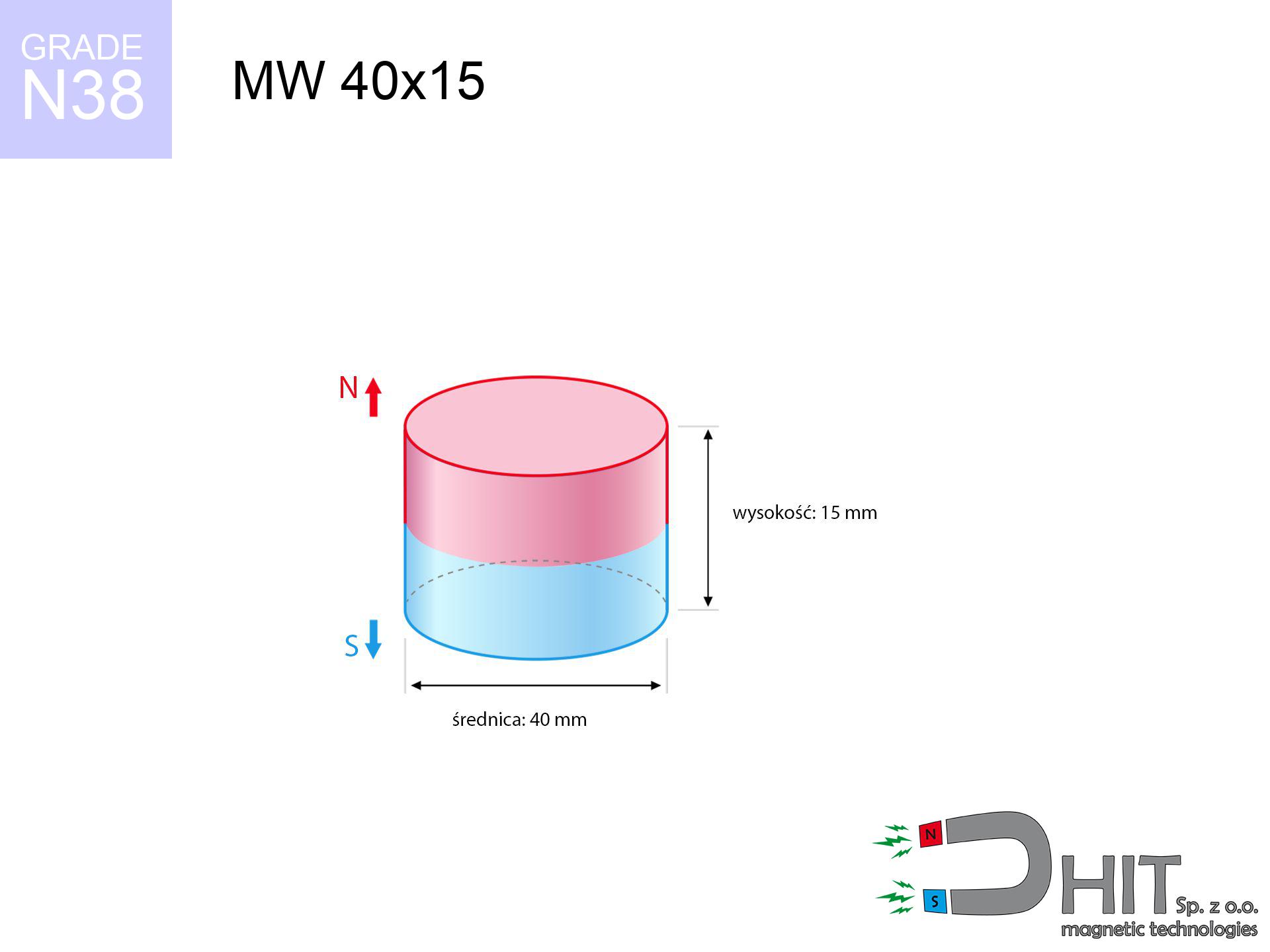
MW 40x15 / N38 - cylindrical magnet
cylindrical magnet
Catalog no 010067
GTIN/EAN: 5906301810667
Diameter Ø
40 mm [±0,1 mm]
Height
15 mm [±0,1 mm]
Weight
141.37 g
Magnetization Direction
↑ axial
Load capacity
42.64 kg / 418.33 N
Magnetic Induction
371.91 mT / 3719 Gs
Coating
[NiCuNi] Nickel
65.93 ZŁ with VAT / pcs + price for transport
53.60 ZŁ net + 23% VAT / pcs
bulk discounts:
Need more?
Give us a call
+48 888 99 98 98
or drop us a message using
form
our website.
Lifting power along with structure of magnetic components can be verified with our
online calculation tool.
Orders placed before 14:00 will be shipped the same business day.
Technical data - MW 40x15 / N38 - cylindrical magnet
Specification / characteristics - MW 40x15 / N38 - cylindrical magnet
| properties | values |
|---|---|
| Cat. no. | 010067 |
| GTIN/EAN | 5906301810667 |
| Production/Distribution | Dhit sp. z o.o. |
| Country of origin | Poland / China / Germany |
| Customs code | 85059029 |
| Diameter Ø | 40 mm [±0,1 mm] |
| Height | 15 mm [±0,1 mm] |
| Weight | 141.37 g |
| Magnetization Direction | ↑ axial |
| Load capacity ~ ? | 42.64 kg / 418.33 N |
| Magnetic Induction ~ ? | 371.91 mT / 3719 Gs |
| Coating | [NiCuNi] Nickel |
| Manufacturing Tolerance | ±0.1 mm |
Magnetic properties of material N38
| properties | values | units |
|---|---|---|
| remenance Br [min. - max.] ? | 12.2-12.6 | kGs |
| remenance Br [min. - max.] ? | 1220-1260 | mT |
| coercivity bHc ? | 10.8-11.5 | kOe |
| coercivity bHc ? | 860-915 | kA/m |
| actual internal force iHc | ≥ 12 | kOe |
| actual internal force iHc | ≥ 955 | kA/m |
| energy density [min. - max.] ? | 36-38 | BH max MGOe |
| energy density [min. - max.] ? | 287-303 | BH max KJ/m |
| max. temperature ? | ≤ 80 | °C |
Physical properties of sintered neodymium magnets Nd2Fe14B at 20°C
| properties | values | units |
|---|---|---|
| Vickers hardness | ≥550 | Hv |
| Density | ≥7.4 | g/cm3 |
| Curie Temperature TC | 312 - 380 | °C |
| Curie Temperature TF | 593 - 716 | °F |
| Specific resistance | 150 | μΩ⋅cm |
| Bending strength | 250 | MPa |
| Compressive strength | 1000~1100 | MPa |
| Thermal expansion parallel (∥) to orientation (M) | (3-4) x 10-6 | °C-1 |
| Thermal expansion perpendicular (⊥) to orientation (M) | -(1-3) x 10-6 | °C-1 |
| Young's modulus | 1.7 x 10⁴ | kg/mm² |
Physical modeling of the product - report
These values represent the direct effect of a physical simulation. Results are based on algorithms for the class Nd2Fe14B. Actual parameters may differ from theoretical values. Treat these data as a supplementary guide during assembly planning.
Table 1: Static force (force vs distance) - power drop
MW 40x15 / N38
| Distance (mm) | Induction (Gauss) / mT | Pull Force (kg/lbs/g/N) | Risk Status |
|---|---|---|---|
| 0 mm |
3718 Gs
371.8 mT
|
42.64 kg / 94.00 LBS
42640.0 g / 418.3 N
|
crushing |
| 1 mm |
3563 Gs
356.3 mT
|
39.16 kg / 86.33 LBS
39159.5 g / 384.2 N
|
crushing |
| 2 mm |
3398 Gs
339.8 mT
|
35.62 kg / 78.52 LBS
35617.1 g / 349.4 N
|
crushing |
| 3 mm |
3228 Gs
322.8 mT
|
32.13 kg / 70.84 LBS
32130.5 g / 315.2 N
|
crushing |
| 5 mm |
2880 Gs
288.0 mT
|
25.58 kg / 56.40 LBS
25584.2 g / 251.0 N
|
crushing |
| 10 mm |
2069 Gs
206.9 mT
|
13.20 kg / 29.09 LBS
13196.7 g / 129.5 N
|
crushing |
| 15 mm |
1439 Gs
143.9 mT
|
6.38 kg / 14.07 LBS
6383.1 g / 62.6 N
|
strong |
| 20 mm |
999 Gs
99.9 mT
|
3.08 kg / 6.79 LBS
3077.9 g / 30.2 N
|
strong |
| 30 mm |
507 Gs
50.7 mT
|
0.79 kg / 1.75 LBS
792.4 g / 7.8 N
|
weak grip |
| 50 mm |
169 Gs
16.9 mT
|
0.09 kg / 0.19 LBS
88.4 g / 0.9 N
|
weak grip |
Table 2: Shear force (vertical surface)
MW 40x15 / N38
| Distance (mm) | Friction coefficient | Pull Force (kg/lbs/g/N) |
|---|---|---|
| 0 mm | Stal (~0.2) |
8.53 kg / 18.80 LBS
8528.0 g / 83.7 N
|
| 1 mm | Stal (~0.2) |
7.83 kg / 17.27 LBS
7832.0 g / 76.8 N
|
| 2 mm | Stal (~0.2) |
7.12 kg / 15.71 LBS
7124.0 g / 69.9 N
|
| 3 mm | Stal (~0.2) |
6.43 kg / 14.17 LBS
6426.0 g / 63.0 N
|
| 5 mm | Stal (~0.2) |
5.12 kg / 11.28 LBS
5116.0 g / 50.2 N
|
| 10 mm | Stal (~0.2) |
2.64 kg / 5.82 LBS
2640.0 g / 25.9 N
|
| 15 mm | Stal (~0.2) |
1.28 kg / 2.81 LBS
1276.0 g / 12.5 N
|
| 20 mm | Stal (~0.2) |
0.62 kg / 1.36 LBS
616.0 g / 6.0 N
|
| 30 mm | Stal (~0.2) |
0.16 kg / 0.35 LBS
158.0 g / 1.5 N
|
| 50 mm | Stal (~0.2) |
0.02 kg / 0.04 LBS
18.0 g / 0.2 N
|
Table 3: Wall mounting (shearing) - vertical pull
MW 40x15 / N38
| Surface type | Friction coefficient / % Mocy | Max load (kg/lbs/g/N) |
|---|---|---|
| Raw steel |
µ = 0.3
30% Nominalnej Siły
|
12.79 kg / 28.20 LBS
12792.0 g / 125.5 N
|
| Painted steel (standard) |
µ = 0.2
20% Nominalnej Siły
|
8.53 kg / 18.80 LBS
8528.0 g / 83.7 N
|
| Oily/slippery steel |
µ = 0.1
10% Nominalnej Siły
|
4.26 kg / 9.40 LBS
4264.0 g / 41.8 N
|
| Magnet with anti-slip rubber |
µ = 0.5
50% Nominalnej Siły
|
21.32 kg / 47.00 LBS
21320.0 g / 209.1 N
|
Table 4: Material efficiency (substrate influence) - sheet metal selection
MW 40x15 / N38
| Steel thickness (mm) | % power | Real pull force (kg/lbs/g/N) |
|---|---|---|
| 0.5 mm |
|
2.13 kg / 4.70 LBS
2132.0 g / 20.9 N
|
| 1 mm |
|
5.33 kg / 11.75 LBS
5330.0 g / 52.3 N
|
| 2 mm |
|
10.66 kg / 23.50 LBS
10660.0 g / 104.6 N
|
| 3 mm |
|
15.99 kg / 35.25 LBS
15990.0 g / 156.9 N
|
| 5 mm |
|
26.65 kg / 58.75 LBS
26650.0 g / 261.4 N
|
| 10 mm |
|
42.64 kg / 94.00 LBS
42640.0 g / 418.3 N
|
| 11 mm |
|
42.64 kg / 94.00 LBS
42640.0 g / 418.3 N
|
| 12 mm |
|
42.64 kg / 94.00 LBS
42640.0 g / 418.3 N
|
Table 5: Thermal stability (material behavior) - power drop
MW 40x15 / N38
| Ambient temp. (°C) | Power loss | Remaining pull (kg/lbs/g/N) | Status |
|---|---|---|---|
| 20 °C | 0.0% |
42.64 kg / 94.00 LBS
42640.0 g / 418.3 N
|
OK |
| 40 °C | -2.2% |
41.70 kg / 91.94 LBS
41701.9 g / 409.1 N
|
OK |
| 60 °C | -4.4% |
40.76 kg / 89.87 LBS
40763.8 g / 399.9 N
|
|
| 80 °C | -6.6% |
39.83 kg / 87.80 LBS
39825.8 g / 390.7 N
|
|
| 100 °C | -28.8% |
30.36 kg / 66.93 LBS
30359.7 g / 297.8 N
|
Table 6: Two magnets (attraction) - field collision
MW 40x15 / N38
| Gap (mm) | Attraction (kg/lbs) (N-S) | Lateral Force (kg/lbs/g/N) | Repulsion (kg/lbs) (N-N) |
|---|---|---|---|
| 0 mm |
107.12 kg / 236.16 LBS
5 156 Gs
|
16.07 kg / 35.42 LBS
16068 g / 157.6 N
|
N/A |
| 1 mm |
102.82 kg / 226.67 LBS
7 286 Gs
|
15.42 kg / 34.00 LBS
15422 g / 151.3 N
|
92.53 kg / 204.00 LBS
~0 Gs
|
| 2 mm |
98.38 kg / 216.89 LBS
7 127 Gs
|
14.76 kg / 32.53 LBS
14757 g / 144.8 N
|
88.54 kg / 195.20 LBS
~0 Gs
|
| 3 mm |
93.92 kg / 207.06 LBS
6 964 Gs
|
14.09 kg / 31.06 LBS
14088 g / 138.2 N
|
84.53 kg / 186.36 LBS
~0 Gs
|
| 5 mm |
85.07 kg / 187.55 LBS
6 627 Gs
|
12.76 kg / 28.13 LBS
12760 g / 125.2 N
|
76.56 kg / 168.79 LBS
~0 Gs
|
| 10 mm |
64.27 kg / 141.70 LBS
5 761 Gs
|
9.64 kg / 21.25 LBS
9641 g / 94.6 N
|
57.85 kg / 127.53 LBS
~0 Gs
|
| 20 mm |
33.15 kg / 73.09 LBS
4 137 Gs
|
4.97 kg / 10.96 LBS
4973 g / 48.8 N
|
29.84 kg / 65.78 LBS
~0 Gs
|
| 50 mm |
3.84 kg / 8.47 LBS
1 408 Gs
|
0.58 kg / 1.27 LBS
576 g / 5.7 N
|
3.46 kg / 7.62 LBS
~0 Gs
|
| 60 mm |
1.99 kg / 4.39 LBS
1 014 Gs
|
0.30 kg / 0.66 LBS
299 g / 2.9 N
|
1.79 kg / 3.95 LBS
~0 Gs
|
| 70 mm |
1.08 kg / 2.38 LBS
747 Gs
|
0.16 kg / 0.36 LBS
162 g / 1.6 N
|
0.97 kg / 2.14 LBS
~0 Gs
|
| 80 mm |
0.61 kg / 1.35 LBS
563 Gs
|
0.09 kg / 0.20 LBS
92 g / 0.9 N
|
0.55 kg / 1.22 LBS
~0 Gs
|
| 90 mm |
0.36 kg / 0.80 LBS
432 Gs
|
0.05 kg / 0.12 LBS
54 g / 0.5 N
|
0.33 kg / 0.72 LBS
~0 Gs
|
| 100 mm |
0.22 kg / 0.49 LBS
339 Gs
|
0.03 kg / 0.07 LBS
33 g / 0.3 N
|
0.20 kg / 0.44 LBS
~0 Gs
|
Table 7: Hazards (implants) - precautionary measures
MW 40x15 / N38
| Object / Device | Limit (Gauss) / mT | Safe distance |
|---|---|---|
| Pacemaker | 5 Gs (0.5 mT) | 19.0 cm |
| Hearing aid | 10 Gs (1.0 mT) | 15.0 cm |
| Timepiece | 20 Gs (2.0 mT) | 11.5 cm |
| Phone / Smartphone | 40 Gs (4.0 mT) | 9.0 cm |
| Car key | 50 Gs (5.0 mT) | 8.5 cm |
| Payment card | 400 Gs (40.0 mT) | 3.5 cm |
| HDD hard drive | 600 Gs (60.0 mT) | 3.0 cm |
Table 8: Collisions (kinetic energy) - collision effects
MW 40x15 / N38
| Start from (mm) | Speed (km/h) | Energy (J) | Predicted outcome |
|---|---|---|---|
| 10 mm |
20.63 km/h
(5.73 m/s)
|
2.32 J | |
| 30 mm |
30.69 km/h
(8.52 m/s)
|
5.14 J | |
| 50 mm |
39.22 km/h
(10.89 m/s)
|
8.39 J | |
| 100 mm |
55.39 km/h
(15.39 m/s)
|
16.73 J |
Table 9: Surface protection spec
MW 40x15 / N38
| Technical parameter | Value / Description |
|---|---|
| Coating type | [NiCuNi] Nickel |
| Layer structure | Nickel - Copper - Nickel |
| Layer thickness | 10-20 µm |
| Salt spray test (SST) ? | 24 h |
| Recommended environment | Indoors only (dry) |
Table 10: Construction data (Flux)
MW 40x15 / N38
| Parameter | Value | SI Unit / Description |
|---|---|---|
| Magnetic Flux | 48 650 Mx | 486.5 µWb |
| Pc Coefficient | 0.48 | Low (Flat) |
Table 11: Hydrostatics and buoyancy
MW 40x15 / N38
| Environment | Effective steel pull | Effect |
|---|---|---|
| Air (land) | 42.64 kg | Standard |
| Water (riverbed) |
48.82 kg
(+6.18 kg buoyancy gain)
|
+14.5% |
1. Sliding resistance
*Note: On a vertical wall, the magnet retains only ~20% of its max power.
2. Plate thickness effect
*Thin steel (e.g. computer case) significantly reduces the holding force.
3. Thermal stability
*For N38 material, the safety limit is 80°C.
4. Demagnetization curve and operating point (B-H)
chart generated for the permeance coefficient Pc (Permeance Coefficient) = 0.48
The chart above illustrates the magnetic characteristics of the material within the second quadrant of the hysteresis loop. The solid red line represents the demagnetization curve (material potential), while the dashed blue line is the load line based on the magnet's geometry. The Pc (Permeance Coefficient), also known as the load line slope, is a dimensionless value that describes the relationship between the magnet's shape and its magnetic stability. The intersection of these two lines (the black dot) is the operating point — it determines the actual magnetic flux density generated by the magnet in this specific configuration. A higher Pc value means the magnet is more 'slender' (tall relative to its area), resulting in a higher operating point and better resistance to irreversible demagnetization caused by external fields or temperature. A value of 0.42 is relatively low (typical for flat magnets), meaning the operating point is closer to the 'knee' of the curve — caution is advised when operating at temperatures near the maximum limit to avoid strength loss.
Chemical composition
| iron (Fe) | 64% – 68% |
| neodymium (Nd) | 29% – 32% |
| boron (B) | 1.1% – 1.2% |
| dysprosium (Dy) | 0.5% – 2.0% |
| coating (Ni-Cu-Ni) | < 0.05% |
Sustainability
| recyclability (EoL) | 100% |
| recycled raw materials | ~10% (pre-cons) |
| carbon footprint | low / zredukowany |
| waste code (EWC) | 16 02 16 |
Other deals

![AM ucho małe [M8] - magnetic accessories](https://cdn3.dhit.pl/graphics/products/am-ucho-małe-m8-zud.jpg "AM ucho małe [M8] - magnetic accessories")
![UI 45x13x6 [C321] / N38 - badge holder](https://cdn3.dhit.pl/graphics/products/ui45x13x6-c321-jic.jpg "UI 45x13x6 [C321] / N38 - badge holder")

Advantages as well as disadvantages of Nd2Fe14B magnets.
Strengths
- They retain magnetic properties for almost ten years – the drop is just ~1% (based on simulations),
- They retain their magnetic properties even under close interference source,
- A magnet with a smooth gold surface has an effective appearance,
- Magnets exhibit impressive magnetic induction on the active area,
- Due to their durability and thermal resistance, neodymium magnets can operate (depending on the shape) even at high temperatures reaching 230°C or more...
- Due to the ability of precise shaping and adaptation to specialized needs, NdFeB magnets can be created in a variety of forms and dimensions, which expands the range of possible applications,
- Wide application in advanced technology sectors – they are utilized in HDD drives, electromotive mechanisms, medical devices, as well as complex engineering applications.
- Relatively small size with high pulling force – neodymium magnets offer impressive pulling force in tiny dimensions, which makes them useful in small systems
Disadvantages
- Brittleness is one of their disadvantages. Upon intense impact they can fracture. We advise keeping them in a special holder, which not only secures them against impacts but also raises their durability
- We warn that neodymium magnets can reduce their strength at high temperatures. To prevent this, we advise our specialized [AH] magnets, which work effectively even at 230°C.
- They oxidize in a humid environment - during use outdoors we suggest using waterproof magnets e.g. in rubber, plastic
- We suggest a housing - magnetic mount, due to difficulties in realizing nuts inside the magnet and complicated forms.
- Potential hazard resulting from small fragments of magnets can be dangerous, if swallowed, which gains importance in the context of child health protection. It is also worth noting that small elements of these devices can be problematic in diagnostics medical in case of swallowing.
- Due to neodymium price, their price exceeds standard values,
Lifting parameters
Maximum lifting force for a neodymium magnet – what affects it?
- on a plate made of mild steel, perfectly concentrating the magnetic field
- whose thickness reaches at least 10 mm
- with a surface cleaned and smooth
- under conditions of no distance (surface-to-surface)
- under perpendicular force direction (90-degree angle)
- in temp. approx. 20°C
Impact of factors on magnetic holding capacity in practice
- Distance (betwixt the magnet and the plate), as even a very small clearance (e.g. 0.5 mm) results in a reduction in force by up to 50% (this also applies to paint, corrosion or dirt).
- Force direction – catalog parameter refers to detachment vertically. When applying parallel force, the magnet holds much less (typically approx. 20-30% of maximum force).
- Metal thickness – thin material does not allow full use of the magnet. Part of the magnetic field passes through the material instead of converting into lifting capacity.
- Steel grade – the best choice is high-permeability steel. Stainless steels may have worse magnetic properties.
- Smoothness – ideal contact is obtained only on smooth steel. Rough texture reduce the real contact area, reducing force.
- Temperature influence – hot environment weakens magnetic field. Exceeding the limit temperature can permanently demagnetize the magnet.
Holding force was measured on the plate surface of 20 mm thickness, when the force acted perpendicularly, in contrast under shearing force the lifting capacity is smaller. Moreover, even a slight gap between the magnet’s surface and the plate lowers the holding force.
Safe handling of neodymium magnets
Keep away from computers
Very strong magnetic fields can corrupt files on credit cards, HDDs, and other magnetic media. Maintain a gap of min. 10 cm.
Product not for children
Adult use only. Small elements pose a choking risk, causing severe trauma. Store out of reach of kids and pets.
Operating temperature
Control the heat. Exposing the magnet to high heat will destroy its properties and strength.
Do not drill into magnets
Drilling and cutting of neodymium magnets poses a fire risk. Magnetic powder oxidizes rapidly with oxygen and is difficult to extinguish.
Threat to navigation
GPS units and mobile phones are extremely sensitive to magnetism. Close proximity with a strong magnet can decalibrate the internal compass in your phone.
Material brittleness
Despite the nickel coating, neodymium is delicate and not impact-resistant. Avoid impacts, as the magnet may crumble into sharp, dangerous pieces.
Physical harm
Watch your fingers. Two powerful magnets will snap together instantly with a force of several hundred kilograms, destroying anything in their path. Be careful!
Danger to pacemakers
For implant holders: Powerful magnets affect medical devices. Keep at least 30 cm distance or ask another person to handle the magnets.
Conscious usage
Be careful. Rare earth magnets attract from a distance and snap with huge force, often quicker than you can move away.
Allergic reactions
Warning for allergy sufferers: The nickel-copper-nickel coating consists of nickel. If an allergic reaction appears, immediately stop working with magnets and use protective gear.
Tabela kosztu i czasu dostawy
Płatność przed wysyłką:

GLS kurier
Przesyłka będzie u Ciebie za 2-3 dni
14.99 ZŁ

InPost Paczkomaty 24/7
Przesyłka będzie u Ciebie za 1-2 dni
12.30 ZŁ
Płatność przy odbiorze (pobranie):
GLS kurier
Przesyłka będzie u Ciebie za 1-2 dni
23.00 ZŁ
Rate the product
Your rating