
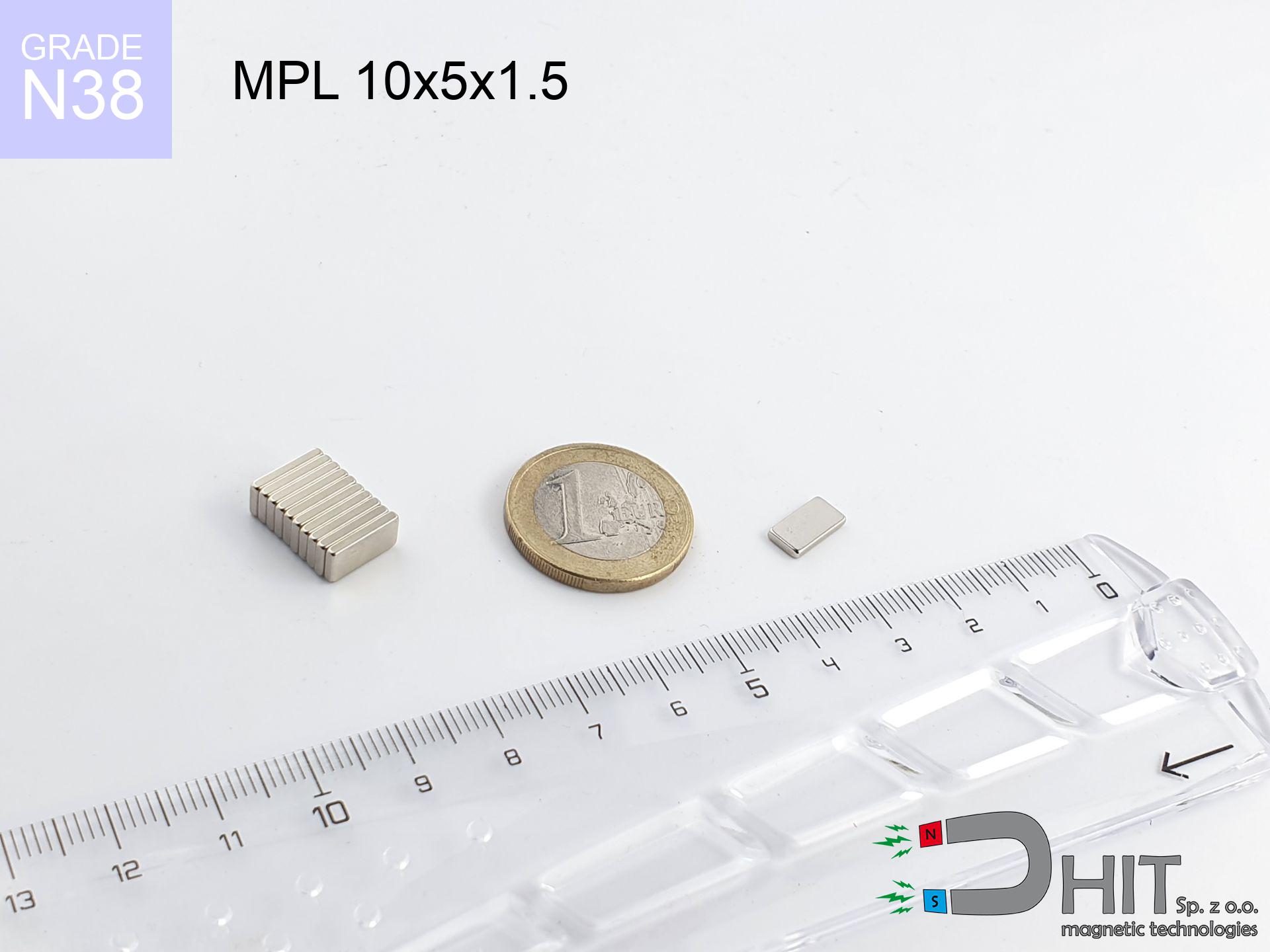
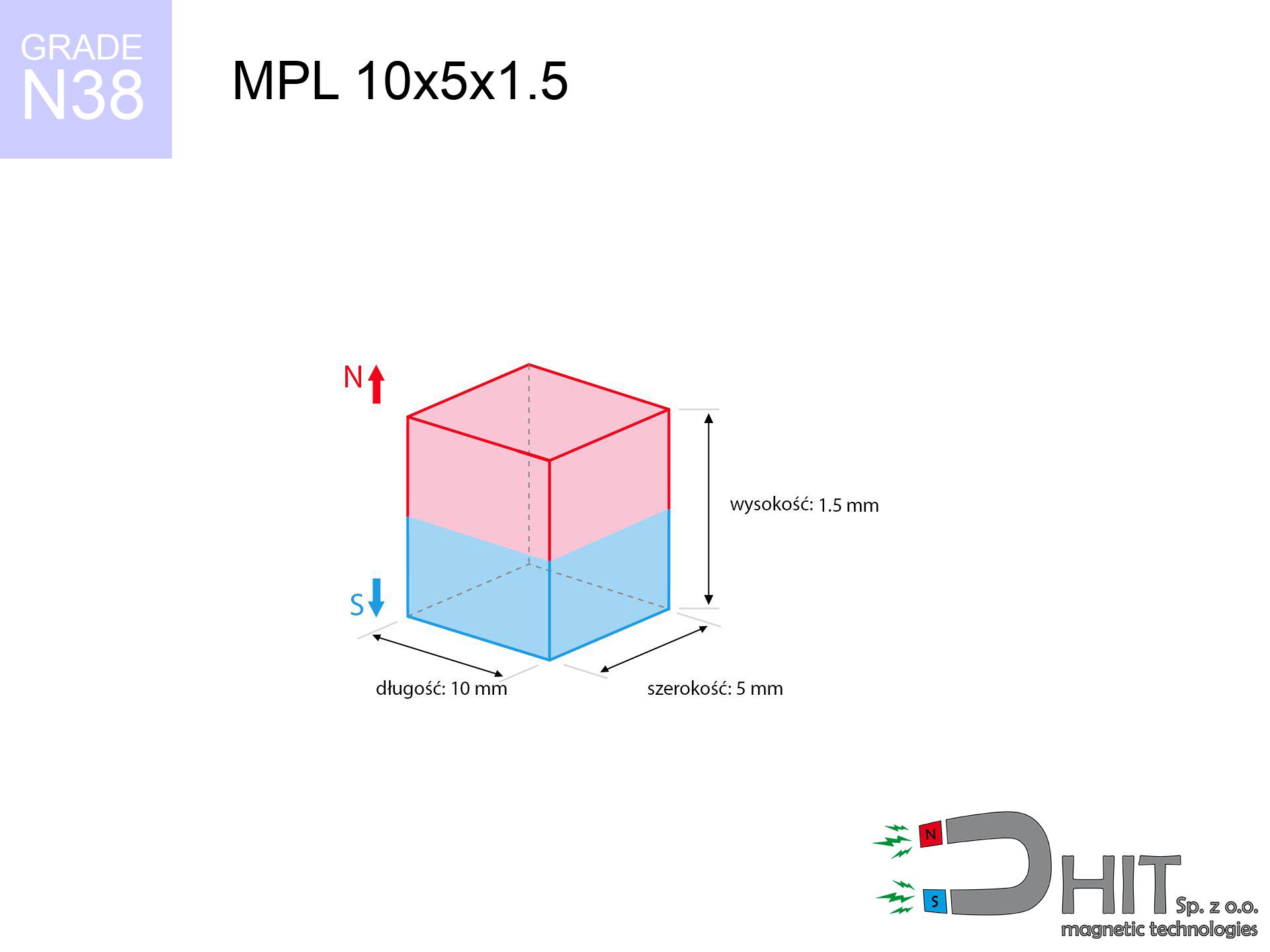
MPL 10x5x1.5 / N38 - lamellar magnet
lamellar magnet
Catalog no 020114
GTIN/EAN: 5906301811206
length
10 mm [±0,1 mm]
Width
5 mm [±0,1 mm]
Height
1.5 mm [±0,1 mm]
Weight
0.56 g
Magnetization Direction
↑ axial
Load capacity
0.86 kg / 8.47 N
Magnetic Induction
239.33 mT / 2393 Gs
Coating
[NiCuNi] Nickel
0.381 ZŁ with VAT / pcs + price for transport
0.310 ZŁ net + 23% VAT / pcs
bulk discounts:
Need more?Engineering report for this magnet
Full PDF analysis: pull and shear force, effect of distance, temperature and plate thickness, safety distances and the demagnetization curve.
Call us now
+48 888 99 98 98
otherwise contact us using
request form
the contact page.
Specifications as well as appearance of magnets can be calculated on our
online calculation tool.
Orders submitted before 14:00 will be dispatched today!
Technical - MPL 10x5x1.5 / N38 - lamellar magnet
Specification / characteristics - MPL 10x5x1.5 / N38 - lamellar magnet
| properties | values |
|---|---|
| Cat. no. | 020114 |
| GTIN/EAN | 5906301811206 |
| Production/Distribution | Dhit sp. z o.o. |
| Country of origin | Poland / China / Germany |
| Customs code | 85059029 |
| length | 10 mm [±0,1 mm] |
| Width | 5 mm [±0,1 mm] |
| Height | 1.5 mm [±0,1 mm] |
| Weight | 0.56 g |
| Magnetization Direction | ↑ axial |
| Load capacity ~ ? | 0.86 kg / 8.47 N |
| Magnetic Induction ~ ? | 239.33 mT / 2393 Gs |
| Coating | [NiCuNi] Nickel |
| Manufacturing Tolerance | ±0.1 mm |
Magnetic properties of material N38
| properties | values | units |
|---|---|---|
| remenance Br [min. - max.] ? | 12.2-12.6 | kGs |
| remenance Br [min. - max.] ? | 1220-1260 | mT |
| coercivity bHc ? | 10.8-11.5 | kOe |
| coercivity bHc ? | 860-915 | kA/m |
| actual internal force iHc | ≥ 12 | kOe |
| actual internal force iHc | ≥ 955 | kA/m |
| energy density [min. - max.] ? | 36-38 | BH max MGOe |
| energy density [min. - max.] ? | 287-303 | BH max KJ/m |
| max. temperature ? | ≤ 80 | °C |
Physical properties of sintered neodymium magnets Nd2Fe14B at 20°C
| properties | values | units |
|---|---|---|
| Vickers hardness | ≥550 | Hv |
| Density | ≥7.4 | g/cm3 |
| Curie Temperature TC | 312 - 380 | °C |
| Curie Temperature TF | 593 - 716 | °F |
| Specific resistance | 150 | μΩ⋅cm |
| Bending strength | 250 | MPa |
| Compressive strength | 1000~1100 | MPa |
| Thermal expansion parallel (∥) to orientation (M) | (3-4) x 10-6 | °C-1 |
| Thermal expansion perpendicular (⊥) to orientation (M) | -(1-3) x 10-6 | °C-1 |
| Young's modulus | 1.7 x 10⁴ | kg/mm² |
Technical analysis of the product - data
Presented information constitute the direct effect of a engineering calculation. Results are based on algorithms for the class Nd2Fe14B. Real-world parameters might slightly deviate from the simulation results. Please consider these calculations as a preliminary roadmap for designers.
Table 1: Static force (pull vs gap) - interaction chart
MPL 10x5x1.5 / N38
| Distance (mm) | Induction (Gauss) / mT | Pull Force (kg/lbs/g/N) | Risk Status |
|---|---|---|---|
| 0 mm |
2392 Gs
239.2 mT
|
0.86 kg / 1.90 LBS
860.0 g / 8.4 N
|
low risk |
| 1 mm |
1814 Gs
181.4 mT
|
0.49 kg / 1.09 LBS
494.9 g / 4.9 N
|
low risk |
| 2 mm |
1242 Gs
124.2 mT
|
0.23 kg / 0.51 LBS
232.1 g / 2.3 N
|
low risk |
| 3 mm |
836 Gs
83.6 mT
|
0.11 kg / 0.23 LBS
105.1 g / 1.0 N
|
low risk |
| 5 mm |
399 Gs
39.9 mT
|
0.02 kg / 0.05 LBS
23.9 g / 0.2 N
|
low risk |
| 10 mm |
94 Gs
9.4 mT
|
0.00 kg / 0.00 LBS
1.3 g / 0.0 N
|
low risk |
| 15 mm |
34 Gs
3.4 mT
|
0.00 kg / 0.00 LBS
0.2 g / 0.0 N
|
low risk |
| 20 mm |
15 Gs
1.5 mT
|
0.00 kg / 0.00 LBS
0.0 g / 0.0 N
|
low risk |
| 30 mm |
5 Gs
0.5 mT
|
0.00 kg / 0.00 LBS
0.0 g / 0.0 N
|
low risk |
| 50 mm |
1 Gs
0.1 mT
|
0.00 kg / 0.00 LBS
0.0 g / 0.0 N
|
low risk |
Table 2: Slippage capacity (vertical surface)
MPL 10x5x1.5 / N38
| Distance (mm) | Friction coefficient | Pull Force (kg/lbs/g/N) |
|---|---|---|
| 0 mm | Stal (~0.2) |
0.17 kg / 0.38 LBS
172.0 g / 1.7 N
|
| 1 mm | Stal (~0.2) |
0.10 kg / 0.22 LBS
98.0 g / 1.0 N
|
| 2 mm | Stal (~0.2) |
0.05 kg / 0.10 LBS
46.0 g / 0.5 N
|
| 3 mm | Stal (~0.2) |
0.02 kg / 0.05 LBS
22.0 g / 0.2 N
|
| 5 mm | Stal (~0.2) |
0.00 kg / 0.01 LBS
4.0 g / 0.0 N
|
| 10 mm | Stal (~0.2) |
0.00 kg / 0.00 LBS
0.0 g / 0.0 N
|
| 15 mm | Stal (~0.2) |
0.00 kg / 0.00 LBS
0.0 g / 0.0 N
|
| 20 mm | Stal (~0.2) |
0.00 kg / 0.00 LBS
0.0 g / 0.0 N
|
| 30 mm | Stal (~0.2) |
0.00 kg / 0.00 LBS
0.0 g / 0.0 N
|
| 50 mm | Stal (~0.2) |
0.00 kg / 0.00 LBS
0.0 g / 0.0 N
|
Table 3: Vertical assembly (shearing) - vertical pull
MPL 10x5x1.5 / N38
| Surface type | Friction coefficient / % Mocy | Max load (kg/lbs/g/N) |
|---|---|---|
| Raw steel |
µ = 0.3
30% Nominalnej Siły
|
0.26 kg / 0.57 LBS
258.0 g / 2.5 N
|
| Painted steel (standard) |
µ = 0.2
20% Nominalnej Siły
|
0.17 kg / 0.38 LBS
172.0 g / 1.7 N
|
| Oily/slippery steel |
µ = 0.1
10% Nominalnej Siły
|
0.09 kg / 0.19 LBS
86.0 g / 0.8 N
|
| Magnet with anti-slip rubber |
µ = 0.5
50% Nominalnej Siły
|
0.43 kg / 0.95 LBS
430.0 g / 4.2 N
|
Table 4: Steel thickness (saturation) - power losses
MPL 10x5x1.5 / N38
| Steel thickness (mm) | % power | Real pull force (kg/lbs/g/N) |
|---|---|---|
| 0.5 mm |
|
0.09 kg / 0.19 LBS
86.0 g / 0.8 N
|
| 1 mm |
|
0.22 kg / 0.47 LBS
215.0 g / 2.1 N
|
| 2 mm |
|
0.43 kg / 0.95 LBS
430.0 g / 4.2 N
|
| 3 mm |
|
0.65 kg / 1.42 LBS
645.0 g / 6.3 N
|
| 5 mm |
|
0.86 kg / 1.90 LBS
860.0 g / 8.4 N
|
| 10 mm |
|
0.86 kg / 1.90 LBS
860.0 g / 8.4 N
|
| 11 mm |
|
0.86 kg / 1.90 LBS
860.0 g / 8.4 N
|
| 12 mm |
|
0.86 kg / 1.90 LBS
860.0 g / 8.4 N
|
Table 5: Thermal resistance (stability) - thermal limit
MPL 10x5x1.5 / N38
| Ambient temp. (°C) | Power loss | Remaining pull (kg/lbs/g/N) | Status |
|---|---|---|---|
| 20 °C | 0.0% |
0.86 kg / 1.90 LBS
860.0 g / 8.4 N
|
OK |
| 40 °C | -2.2% |
0.84 kg / 1.85 LBS
841.1 g / 8.3 N
|
OK |
| 60 °C | -4.4% |
0.82 kg / 1.81 LBS
822.2 g / 8.1 N
|
|
| 80 °C | -6.6% |
0.80 kg / 1.77 LBS
803.2 g / 7.9 N
|
|
| 100 °C | -28.8% |
0.61 kg / 1.35 LBS
612.3 g / 6.0 N
|
Table 6: Two magnets (repulsion) - field collision
MPL 10x5x1.5 / N38
| Gap (mm) | Attraction (kg/lbs) (N-S) | Shear Force (kg/lbs/g/N) | Repulsion (kg/lbs) (N-N) |
|---|---|---|---|
| 0 mm |
1.76 kg / 3.89 LBS
3 896 Gs
|
0.26 kg / 0.58 LBS
264 g / 2.6 N
|
N/A |
| 1 mm |
1.39 kg / 3.07 LBS
4 254 Gs
|
0.21 kg / 0.46 LBS
209 g / 2.1 N
|
1.26 kg / 2.77 LBS
~0 Gs
|
| 2 mm |
1.01 kg / 2.24 LBS
3 628 Gs
|
0.15 kg / 0.34 LBS
152 g / 1.5 N
|
0.91 kg / 2.01 LBS
~0 Gs
|
| 3 mm |
0.70 kg / 1.55 LBS
3 020 Gs
|
0.11 kg / 0.23 LBS
105 g / 1.0 N
|
0.63 kg / 1.39 LBS
~0 Gs
|
| 5 mm |
0.32 kg / 0.70 LBS
2 037 Gs
|
0.05 kg / 0.11 LBS
48 g / 0.5 N
|
0.29 kg / 0.63 LBS
~0 Gs
|
| 10 mm |
0.05 kg / 0.11 LBS
798 Gs
|
0.01 kg / 0.02 LBS
7 g / 0.1 N
|
0.04 kg / 0.10 LBS
~0 Gs
|
| 20 mm |
0.00 kg / 0.01 LBS
188 Gs
|
0.00 kg / 0.00 LBS
0 g / 0.0 N
|
0.00 kg / 0.00 LBS
~0 Gs
|
| 50 mm |
0.00 kg / 0.00 LBS
17 Gs
|
0.00 kg / 0.00 LBS
0 g / 0.0 N
|
0.00 kg / 0.00 LBS
~0 Gs
|
| 60 mm |
0.00 kg / 0.00 LBS
10 Gs
|
0.00 kg / 0.00 LBS
0 g / 0.0 N
|
0.00 kg / 0.00 LBS
~0 Gs
|
| 70 mm |
0.00 kg / 0.00 LBS
6 Gs
|
0.00 kg / 0.00 LBS
0 g / 0.0 N
|
0.00 kg / 0.00 LBS
~0 Gs
|
| 80 mm |
0.00 kg / 0.00 LBS
4 Gs
|
0.00 kg / 0.00 LBS
0 g / 0.0 N
|
0.00 kg / 0.00 LBS
~0 Gs
|
| 90 mm |
0.00 kg / 0.00 LBS
3 Gs
|
0.00 kg / 0.00 LBS
0 g / 0.0 N
|
0.00 kg / 0.00 LBS
~0 Gs
|
| 100 mm |
0.00 kg / 0.00 LBS
2 Gs
|
0.00 kg / 0.00 LBS
0 g / 0.0 N
|
0.00 kg / 0.00 LBS
~0 Gs
|
Table 7: Safety (HSE) (electronics) - warnings
MPL 10x5x1.5 / N38
| Object / Device | Limit (Gauss) / mT | Safe distance |
|---|---|---|
| Pacemaker | 5 Gs (0.5 mT) | 3.0 cm |
| Hearing aid | 10 Gs (1.0 mT) | 2.5 cm |
| Mechanical watch | 20 Gs (2.0 mT) | 2.0 cm |
| Mobile device | 40 Gs (4.0 mT) | 1.5 cm |
| Remote | 50 Gs (5.0 mT) | 1.5 cm |
| Payment card | 400 Gs (40.0 mT) | 0.5 cm |
| HDD hard drive | 600 Gs (60.0 mT) | 0.5 cm |
Table 8: Dynamics (cracking risk) - warning
MPL 10x5x1.5 / N38
| Start from (mm) | Speed (km/h) | Energy (J) | Predicted outcome |
|---|---|---|---|
| 10 mm |
39.56 km/h
(10.99 m/s)
|
0.03 J | |
| 30 mm |
68.45 km/h
(19.02 m/s)
|
0.10 J | |
| 50 mm |
88.37 km/h
(24.55 m/s)
|
0.17 J | |
| 100 mm |
124.98 km/h
(34.72 m/s)
|
0.34 J |
Table 9: Anti-corrosion coating durability
MPL 10x5x1.5 / N38
| Technical parameter | Value / Description |
|---|---|
| Coating type | [NiCuNi] Nickel |
| Layer structure | Nickel - Copper - Nickel |
| Layer thickness | 10-20 µm |
| Salt spray test (SST) ? | 24 h |
| Recommended environment | Indoors only (dry) |
Table 10: Construction data (Pc)
MPL 10x5x1.5 / N38
| Parameter | Value | SI Unit / Description |
|---|---|---|
| Magnetic Flux | 1 281 Mx | 12.8 µWb |
| Pc Coefficient | 0.27 | Low (Flat) |
Table 11: Underwater work (magnet fishing)
MPL 10x5x1.5 / N38
| Environment | Effective steel pull | Effect |
|---|---|---|
| Air (land) | 0.86 kg | Standard |
| Water (riverbed) |
0.98 kg
(+0.12 kg buoyancy gain)
|
+14.5% |
1. Shear force
*Note: On a vertical surface, the magnet retains merely approx. 20-30% of its perpendicular strength.
2. Efficiency vs thickness
*Thin metal sheet (e.g. 0.5mm PC case) significantly weakens the holding force.
3. Temperature resistance
*For N38 grade, the safety limit is 80°C.
4. Demagnetization curve and operating point (B-H)
chart generated for the permeance coefficient Pc (Permeance Coefficient) = 0.27
The chart above illustrates the magnetic characteristics of the material within the second quadrant of the hysteresis loop. The solid red line represents the demagnetization curve (material potential), while the dashed blue line is the load line based on the magnet's geometry. The Pc (Permeance Coefficient), also known as the load line slope, is a dimensionless value that describes the relationship between the magnet's shape and its magnetic stability. The intersection of these two lines (the black dot) is the operating point — it determines the actual magnetic flux density generated by the magnet in this specific configuration. A higher Pc value means the magnet is more 'slender' (tall relative to its area), resulting in a higher operating point and better resistance to irreversible demagnetization caused by external fields or temperature. A value of 0.42 is relatively low (typical for flat magnets), meaning the operating point is closer to the 'knee' of the curve — caution is advised when operating at temperatures near the maximum limit to avoid strength loss.
Chemical composition
| iron (Fe) | 64% – 68% |
| neodymium (Nd) | 29% – 32% |
| boron (B) | 1.1% – 1.2% |
| dysprosium (Dy) | 0.5% – 2.0% |
| coating (Ni-Cu-Ni) | < 0.05% |
Ecology and recycling (GPSR)
| recyclability (EoL) | 100% |
| recycled raw materials | ~10% (pre-cons) |
| carbon footprint | low / zredukowany |
| waste code (EWC) | 16 02 16 |
View also proposals


Advantages and disadvantages of neodymium magnets.
Benefits
- Their power remains stable, and after approximately 10 years it drops only by ~1% (theoretically),
- They possess excellent resistance to magnetism drop as a result of opposing magnetic fields,
- Thanks to the metallic finish, the surface of nickel, gold-plated, or silver gives an aesthetic appearance,
- The surface of neodymium magnets generates a unique magnetic field – this is one of their assets,
- Due to their durability and thermal resistance, neodymium magnets are capable of operate (depending on the form) even at high temperatures reaching 230°C or more...
- Thanks to the possibility of accurate shaping and customization to unique solutions, neodymium magnets can be modeled in a broad palette of forms and dimensions, which expands the range of possible applications,
- Versatile presence in modern technologies – they find application in magnetic memories, electric drive systems, precision medical tools, and technologically advanced constructions.
- Relatively small size with high pulling force – neodymium magnets offer strong magnetic field in tiny dimensions, which allows their use in compact constructions
Disadvantages
- They are prone to damage upon heavy impacts. To avoid cracks, it is worth protecting magnets in special housings. Such protection not only protects the magnet but also improves its resistance to damage
- We warn that neodymium magnets can lose their strength at high temperatures. To prevent this, we advise our specialized [AH] magnets, which work effectively even at 230°C.
- They oxidize in a humid environment - during use outdoors we suggest using waterproof magnets e.g. in rubber, plastic
- We recommend a housing - magnetic mount, due to difficulties in creating threads inside the magnet and complicated shapes.
- Potential hazard to health – tiny shards of magnets pose a threat, if swallowed, which becomes key in the context of child safety. Additionally, small elements of these devices can complicate diagnosis medical in case of swallowing.
- Higher cost of purchase is one of the disadvantages compared to ceramic magnets, especially in budget applications
Lifting parameters
Maximum lifting capacity of the magnet – what affects it?
- with the contact of a yoke made of low-carbon steel, guaranteeing full magnetic saturation
- with a thickness of at least 10 mm
- characterized by even structure
- with total lack of distance (without coatings)
- for force acting at a right angle (in the magnet axis)
- at ambient temperature approx. 20 degrees Celsius
Impact of factors on magnetic holding capacity in practice
- Space between surfaces – every millimeter of distance (caused e.g. by veneer or dirt) significantly weakens the pulling force, often by half at just 0.5 mm.
- Direction of force – highest force is reached only during perpendicular pulling. The force required to slide of the magnet along the surface is typically many times smaller (approx. 1/5 of the lifting capacity).
- Metal thickness – thin material does not allow full use of the magnet. Part of the magnetic field penetrates through instead of generating force.
- Material type – ideal substrate is high-permeability steel. Stainless steels may generate lower lifting capacity.
- Smoothness – full contact is obtained only on polished steel. Rough texture create air cushions, weakening the magnet.
- Thermal environment – heating the magnet results in weakening of force. It is worth remembering the maximum operating temperature for a given model.
Holding force was checked on the plate surface of 20 mm thickness, when the force acted perpendicularly, however under parallel forces the holding force is lower. In addition, even a slight gap between the magnet and the plate reduces the lifting capacity.
Precautions when working with neodymium magnets
Powerful field
Be careful. Neodymium magnets act from a distance and connect with massive power, often faster than you can move away.
Shattering risk
Despite metallic appearance, the material is brittle and not impact-resistant. Do not hit, as the magnet may crumble into hazardous fragments.
Thermal limits
Standard neodymium magnets (grade N) undergo demagnetization when the temperature exceeds 80°C. The loss of strength is permanent.
Magnetic interference
Note: rare earth magnets generate a field that confuses precision electronics. Maintain a separation from your phone, device, and navigation systems.
Magnetic media
Device Safety: Neodymium magnets can ruin payment cards and delicate electronics (heart implants, medical aids, timepieces).
Danger to the youngest
Strictly store magnets out of reach of children. Risk of swallowing is significant, and the consequences of magnets connecting inside the body are very dangerous.
Pinching danger
Large magnets can break fingers instantly. Under no circumstances place your hand between two strong magnets.
Metal Allergy
Studies show that the nickel plating (standard magnet coating) is a common allergen. If your skin reacts to metals, prevent touching magnets with bare hands and opt for encased magnets.
Life threat
Health Alert: Neodymium magnets can turn off heart devices and defibrillators. Do not approach if you have electronic implants.
Flammability
Powder created during machining of magnets is self-igniting. Do not drill into magnets unless you are an expert.
Tabela kosztu i czasu dostawy
Płatność przed wysyłką:

GLS kurier
Przesyłka będzie u Ciebie za 2-3 dni
14.99 ZŁ

InPost Paczkomaty 24/7
Przesyłka będzie u Ciebie za 1-2 dni
12.30 ZŁ
Płatność przy odbiorze (pobranie):
GLS kurier
Przesyłka będzie u Ciebie za 1-2 dni
23.00 ZŁ
Rate the product
Your rating