
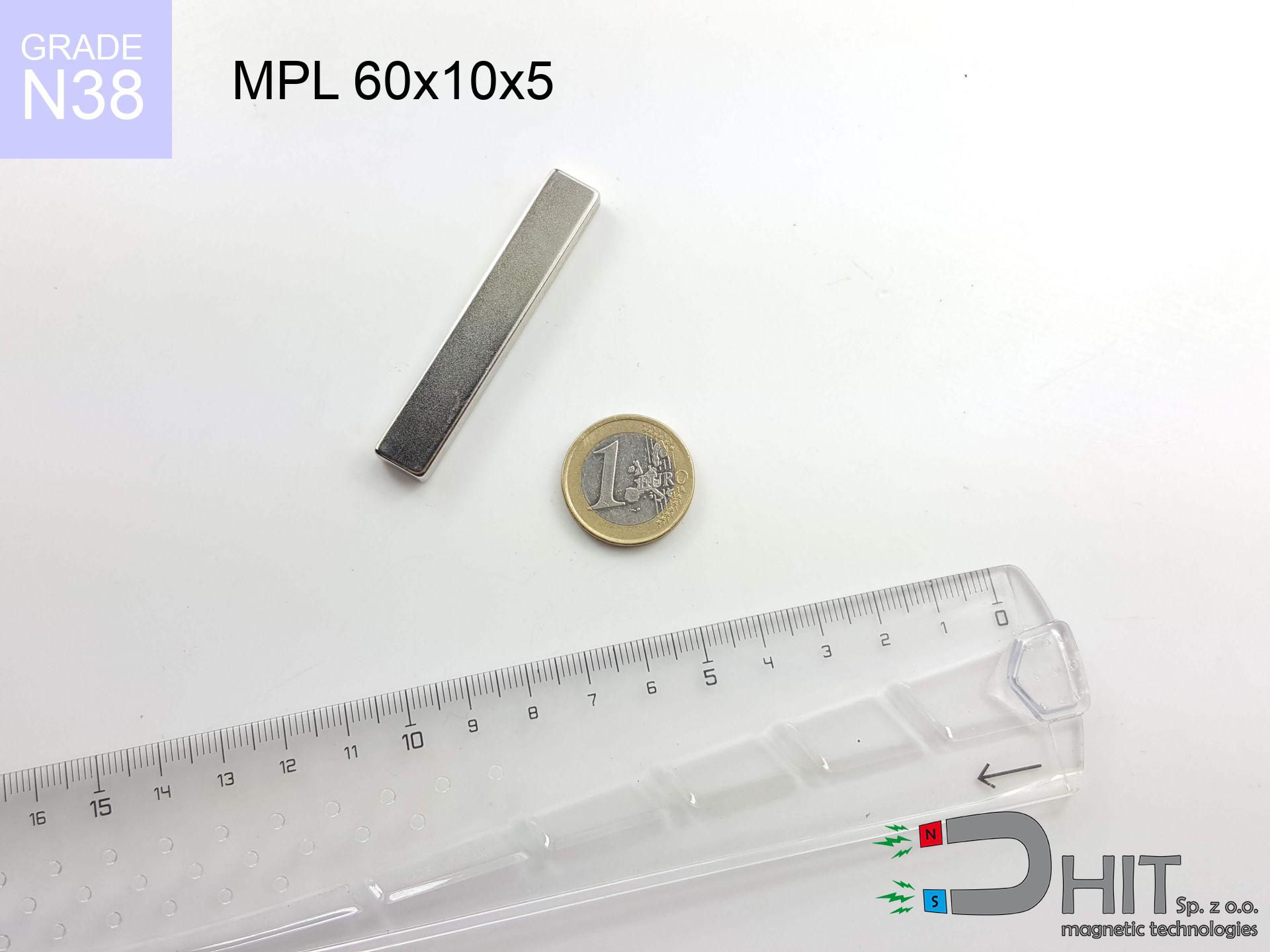
MPL 60x10x5 / N38 - lamellar magnet
lamellar magnet
Catalog no 020474
GTIN/EAN: 5906301811947
length
60 mm [±0,1 mm]
Width
10 mm [±0,1 mm]
Height
5 mm [±0,1 mm]
Weight
22.5 g
Magnetization Direction
↑ axial
Load capacity
18.16 kg / 178.10 N
Magnetic Induction
315.09 mT / 3151 Gs
Coating
[NiCuNi] Nickel
19.00 ZŁ with VAT / pcs + price for transport
15.45 ZŁ net + 23% VAT / pcs
bulk discounts:
Need more?
Contact us by phone
+48 22 499 98 98
if you prefer let us know by means of
our online form
the contact page.
Weight as well as shape of a neodymium magnet can be calculated using our
online calculation tool.
Same-day shipping for orders placed before 14:00.
Technical details - MPL 60x10x5 / N38 - lamellar magnet
Specification / characteristics - MPL 60x10x5 / N38 - lamellar magnet
| properties | values |
|---|---|
| Cat. no. | 020474 |
| GTIN/EAN | 5906301811947 |
| Production/Distribution | Dhit sp. z o.o. |
| Country of origin | Poland / China / Germany |
| Customs code | 85059029 |
| length | 60 mm [±0,1 mm] |
| Width | 10 mm [±0,1 mm] |
| Height | 5 mm [±0,1 mm] |
| Weight | 22.5 g |
| Magnetization Direction | ↑ axial |
| Load capacity ~ ? | 18.16 kg / 178.10 N |
| Magnetic Induction ~ ? | 315.09 mT / 3151 Gs |
| Coating | [NiCuNi] Nickel |
| Manufacturing Tolerance | ±0.1 mm |
Magnetic properties of material N38
| properties | values | units |
|---|---|---|
| remenance Br [min. - max.] ? | 12.2-12.6 | kGs |
| remenance Br [min. - max.] ? | 1220-1260 | mT |
| coercivity bHc ? | 10.8-11.5 | kOe |
| coercivity bHc ? | 860-915 | kA/m |
| actual internal force iHc | ≥ 12 | kOe |
| actual internal force iHc | ≥ 955 | kA/m |
| energy density [min. - max.] ? | 36-38 | BH max MGOe |
| energy density [min. - max.] ? | 287-303 | BH max KJ/m |
| max. temperature ? | ≤ 80 | °C |
Physical properties of sintered neodymium magnets Nd2Fe14B at 20°C
| properties | values | units |
|---|---|---|
| Vickers hardness | ≥550 | Hv |
| Density | ≥7.4 | g/cm3 |
| Curie Temperature TC | 312 - 380 | °C |
| Curie Temperature TF | 593 - 716 | °F |
| Specific resistance | 150 | μΩ⋅cm |
| Bending strength | 250 | MPa |
| Compressive strength | 1000~1100 | MPa |
| Thermal expansion parallel (∥) to orientation (M) | (3-4) x 10-6 | °C-1 |
| Thermal expansion perpendicular (⊥) to orientation (M) | -(1-3) x 10-6 | °C-1 |
| Young's modulus | 1.7 x 10⁴ | kg/mm² |
Physical modeling of the assembly - technical parameters
These data represent the result of a physical calculation. Results were calculated on algorithms for the material Nd2Fe14B. Actual conditions may deviate from the simulation results. Treat these data as a supplementary guide for designers.
Table 1: Static pull force (pull vs gap) - characteristics
MPL 60x10x5 / N38
| Distance (mm) | Induction (Gauss) / mT | Pull Force (kg/lbs/g/N) | Risk Status |
|---|---|---|---|
| 0 mm |
3149 Gs
314.9 mT
|
18.16 kg / 40.04 lbs
18160.0 g / 178.1 N
|
crushing |
| 1 mm |
2731 Gs
273.1 mT
|
13.66 kg / 30.11 lbs
13658.3 g / 134.0 N
|
crushing |
| 2 mm |
2302 Gs
230.2 mT
|
9.70 kg / 21.38 lbs
9698.4 g / 95.1 N
|
warning |
| 3 mm |
1912 Gs
191.2 mT
|
6.70 kg / 14.76 lbs
6696.5 g / 65.7 N
|
warning |
| 5 mm |
1317 Gs
131.7 mT
|
3.18 kg / 7.00 lbs
3176.9 g / 31.2 N
|
warning |
| 10 mm |
598 Gs
59.8 mT
|
0.65 kg / 1.44 lbs
653.8 g / 6.4 N
|
safe |
| 15 mm |
330 Gs
33.0 mT
|
0.20 kg / 0.44 lbs
199.2 g / 2.0 N
|
safe |
| 20 mm |
205 Gs
20.5 mT
|
0.08 kg / 0.17 lbs
77.0 g / 0.8 N
|
safe |
| 30 mm |
96 Gs
9.6 mT
|
0.02 kg / 0.04 lbs
16.9 g / 0.2 N
|
safe |
| 50 mm |
31 Gs
3.1 mT
|
0.00 kg / 0.00 lbs
1.8 g / 0.0 N
|
safe |
Table 2: Slippage force (vertical surface)
MPL 60x10x5 / N38
| Distance (mm) | Friction coefficient | Pull Force (kg/lbs/g/N) |
|---|---|---|
| 0 mm | Stal (~0.2) |
3.63 kg / 8.01 lbs
3632.0 g / 35.6 N
|
| 1 mm | Stal (~0.2) |
2.73 kg / 6.02 lbs
2732.0 g / 26.8 N
|
| 2 mm | Stal (~0.2) |
1.94 kg / 4.28 lbs
1940.0 g / 19.0 N
|
| 3 mm | Stal (~0.2) |
1.34 kg / 2.95 lbs
1340.0 g / 13.1 N
|
| 5 mm | Stal (~0.2) |
0.64 kg / 1.40 lbs
636.0 g / 6.2 N
|
| 10 mm | Stal (~0.2) |
0.13 kg / 0.29 lbs
130.0 g / 1.3 N
|
| 15 mm | Stal (~0.2) |
0.04 kg / 0.09 lbs
40.0 g / 0.4 N
|
| 20 mm | Stal (~0.2) |
0.02 kg / 0.04 lbs
16.0 g / 0.2 N
|
| 30 mm | Stal (~0.2) |
0.00 kg / 0.01 lbs
4.0 g / 0.0 N
|
| 50 mm | Stal (~0.2) |
0.00 kg / 0.00 lbs
0.0 g / 0.0 N
|
Table 3: Vertical assembly (shearing) - vertical pull
MPL 60x10x5 / N38
| Surface type | Friction coefficient / % Mocy | Max load (kg/lbs/g/N) |
|---|---|---|
| Raw steel |
µ = 0.3
30% Nominalnej Siły
|
5.45 kg / 12.01 lbs
5448.0 g / 53.4 N
|
| Painted steel (standard) |
µ = 0.2
20% Nominalnej Siły
|
3.63 kg / 8.01 lbs
3632.0 g / 35.6 N
|
| Oily/slippery steel |
µ = 0.1
10% Nominalnej Siły
|
1.82 kg / 4.00 lbs
1816.0 g / 17.8 N
|
| Magnet with anti-slip rubber |
µ = 0.5
50% Nominalnej Siły
|
9.08 kg / 20.02 lbs
9080.0 g / 89.1 N
|
Table 4: Material efficiency (substrate influence) - sheet metal selection
MPL 60x10x5 / N38
| Steel thickness (mm) | % power | Real pull force (kg/lbs/g/N) |
|---|---|---|
| 0.5 mm |
|
0.91 kg / 2.00 lbs
908.0 g / 8.9 N
|
| 1 mm |
|
2.27 kg / 5.00 lbs
2270.0 g / 22.3 N
|
| 2 mm |
|
4.54 kg / 10.01 lbs
4540.0 g / 44.5 N
|
| 3 mm |
|
6.81 kg / 15.01 lbs
6810.0 g / 66.8 N
|
| 5 mm |
|
11.35 kg / 25.02 lbs
11350.0 g / 111.3 N
|
| 10 mm |
|
18.16 kg / 40.04 lbs
18160.0 g / 178.1 N
|
| 11 mm |
|
18.16 kg / 40.04 lbs
18160.0 g / 178.1 N
|
| 12 mm |
|
18.16 kg / 40.04 lbs
18160.0 g / 178.1 N
|
Table 5: Working in heat (material behavior) - thermal limit
MPL 60x10x5 / N38
| Ambient temp. (°C) | Power loss | Remaining pull (kg/lbs/g/N) | Status |
|---|---|---|---|
| 20 °C | 0.0% |
18.16 kg / 40.04 lbs
18160.0 g / 178.1 N
|
OK |
| 40 °C | -2.2% |
17.76 kg / 39.16 lbs
17760.5 g / 174.2 N
|
OK |
| 60 °C | -4.4% |
17.36 kg / 38.27 lbs
17361.0 g / 170.3 N
|
|
| 80 °C | -6.6% |
16.96 kg / 37.39 lbs
16961.4 g / 166.4 N
|
|
| 100 °C | -28.8% |
12.93 kg / 28.51 lbs
12929.9 g / 126.8 N
|
Table 6: Two magnets (attraction) - field range
MPL 60x10x5 / N38
| Gap (mm) | Attraction (kg/lbs) (N-S) | Sliding Force (kg/lbs/g/N) | Repulsion (kg/lbs) (N-N) |
|---|---|---|---|
| 0 mm |
36.69 kg / 80.89 lbs
4 464 Gs
|
5.50 kg / 12.13 lbs
5503 g / 54.0 N
|
N/A |
| 1 mm |
32.13 kg / 70.84 lbs
5 895 Gs
|
4.82 kg / 10.63 lbs
4820 g / 47.3 N
|
28.92 kg / 63.76 lbs
~0 Gs
|
| 2 mm |
27.59 kg / 60.83 lbs
5 463 Gs
|
4.14 kg / 9.13 lbs
4139 g / 40.6 N
|
24.83 kg / 54.75 lbs
~0 Gs
|
| 3 mm |
23.37 kg / 51.53 lbs
5 027 Gs
|
3.51 kg / 7.73 lbs
3506 g / 34.4 N
|
21.03 kg / 46.37 lbs
~0 Gs
|
| 5 mm |
16.31 kg / 35.97 lbs
4 200 Gs
|
2.45 kg / 5.39 lbs
2447 g / 24.0 N
|
14.68 kg / 32.37 lbs
~0 Gs
|
| 10 mm |
6.42 kg / 14.15 lbs
2 635 Gs
|
0.96 kg / 2.12 lbs
963 g / 9.4 N
|
5.78 kg / 12.74 lbs
~0 Gs
|
| 20 mm |
1.32 kg / 2.91 lbs
1 195 Gs
|
0.20 kg / 0.44 lbs
198 g / 1.9 N
|
1.19 kg / 2.62 lbs
~0 Gs
|
| 50 mm |
0.07 kg / 0.15 lbs
274 Gs
|
0.01 kg / 0.02 lbs
10 g / 0.1 N
|
0.06 kg / 0.14 lbs
~0 Gs
|
| 60 mm |
0.03 kg / 0.08 lbs
192 Gs
|
0.01 kg / 0.01 lbs
5 g / 0.1 N
|
0.03 kg / 0.07 lbs
~0 Gs
|
| 70 mm |
0.02 kg / 0.04 lbs
140 Gs
|
0.00 kg / 0.01 lbs
3 g / 0.0 N
|
0.02 kg / 0.04 lbs
~0 Gs
|
| 80 mm |
0.01 kg / 0.02 lbs
104 Gs
|
0.00 kg / 0.00 lbs
2 g / 0.0 N
|
0.01 kg / 0.02 lbs
~0 Gs
|
| 90 mm |
0.01 kg / 0.01 lbs
80 Gs
|
0.00 kg / 0.00 lbs
1 g / 0.0 N
|
0.00 kg / 0.00 lbs
~0 Gs
|
| 100 mm |
0.00 kg / 0.01 lbs
62 Gs
|
0.00 kg / 0.00 lbs
1 g / 0.0 N
|
0.00 kg / 0.00 lbs
~0 Gs
|
Table 7: Hazards (electronics) - precautionary measures
MPL 60x10x5 / N38
| Object / Device | Limit (Gauss) / mT | Safe distance |
|---|---|---|
| Pacemaker | 5 Gs (0.5 mT) | 10.5 cm |
| Hearing aid | 10 Gs (1.0 mT) | 8.0 cm |
| Mechanical watch | 20 Gs (2.0 mT) | 6.0 cm |
| Phone / Smartphone | 40 Gs (4.0 mT) | 4.5 cm |
| Remote | 50 Gs (5.0 mT) | 4.5 cm |
| Payment card | 400 Gs (40.0 mT) | 1.5 cm |
| HDD hard drive | 600 Gs (60.0 mT) | 1.0 cm |
Table 8: Collisions (kinetic energy) - collision effects
MPL 60x10x5 / N38
| Start from (mm) | Speed (km/h) | Energy (J) | Predicted outcome |
|---|---|---|---|
| 10 mm |
29.29 km/h
(8.14 m/s)
|
0.74 J | |
| 30 mm |
49.65 km/h
(13.79 m/s)
|
2.14 J | |
| 50 mm |
64.07 km/h
(17.80 m/s)
|
3.56 J | |
| 100 mm |
90.60 km/h
(25.17 m/s)
|
7.13 J |
Table 9: Surface protection spec
MPL 60x10x5 / N38
| Technical parameter | Value / Description |
|---|---|
| Coating type | [NiCuNi] Nickel |
| Layer structure | Nickel - Copper - Nickel |
| Layer thickness | 10-20 µm |
| Salt spray test (SST) ? | 24 h |
| Recommended environment | Indoors only (dry) |
Table 10: Construction data (Pc)
MPL 60x10x5 / N38
| Parameter | Value | SI Unit / Description |
|---|---|---|
| Magnetic Flux | 14 969 Mx | 149.7 µWb |
| Pc Coefficient | 0.26 | Low (Flat) |
Table 11: Submerged application
MPL 60x10x5 / N38
| Environment | Effective steel pull | Effect |
|---|---|---|
| Air (land) | 18.16 kg | Standard |
| Water (riverbed) |
20.79 kg
(+2.63 kg buoyancy gain)
|
+14.5% |
1. Vertical hold
*Note: On a vertical surface, the magnet retains merely ~20% of its max power.
2. Steel thickness impact
*Thin steel (e.g. computer case) severely weakens the holding force.
3. Temperature resistance
*For standard magnets, the safety limit is 80°C.
4. Demagnetization curve and operating point (B-H)
chart generated for the permeance coefficient Pc (Permeance Coefficient) = 0.26
This simulation demonstrates the magnetic stability of the selected magnet under specific geometric conditions. The solid red line represents the demagnetization curve (material potential), while the dashed blue line is the load line based on the magnet's geometry. The Pc (Permeance Coefficient), also known as the load line slope, is a dimensionless value that describes the relationship between the magnet's shape and its magnetic stability. The intersection of these two lines (the black dot) is the operating point — it determines the actual magnetic flux density generated by the magnet in this specific configuration. A higher Pc value means the magnet is more 'slender' (tall relative to its area), resulting in a higher operating point and better resistance to irreversible demagnetization caused by external fields or temperature. A value of 0.42 is relatively low (typical for flat magnets), meaning the operating point is closer to the 'knee' of the curve — caution is advised when operating at temperatures near the maximum limit to avoid strength loss.
Material specification
| iron (Fe) | 64% – 68% |
| neodymium (Nd) | 29% – 32% |
| boron (B) | 1.1% – 1.2% |
| dysprosium (Dy) | 0.5% – 2.0% |
| coating (Ni-Cu-Ni) | < 0.05% |
Environmental data
| recyclability (EoL) | 100% |
| recycled raw materials | ~10% (pre-cons) |
| carbon footprint | low / zredukowany |
| waste code (EWC) | 16 02 16 |
See more products
![SM 25x200 [2xM8] / N52 - magnetic separator](https://cdn3.dhit.pl/graphics/products/sm-25x200-2xm8-jas.jpg "SM 25x200 [2xM8] / N52 - magnetic separator")
![UMP 75x25 [M10x3] GW F200 PLATINIUM / N52 - search holder](https://cdn3.dhit.pl/graphics/products/ump-75x25-m10x3-gw-f200-platinium-tav.jpg "UMP 75x25 [M10x3] GW F200 PLATINIUM / N52 - search holder")
![UMGW 42x20x9 [M6] GW / N38 - magnetic holder internal thread](https://cdn3.dhit.pl/graphics/products/um-42x20x9-m8-gw-god.jpg "UMGW 42x20x9 [M6] GW / N38 - magnetic holder internal thread")

Pros as well as cons of neodymium magnets.
Advantages
- They retain magnetic properties for almost ten years – the drop is just ~1% (according to analyses),
- Neodymium magnets are distinguished by exceptionally resistant to demagnetization caused by external interference,
- Thanks to the smooth finish, the surface of Ni-Cu-Ni, gold, or silver gives an aesthetic appearance,
- Neodymium magnets create maximum magnetic induction on a small surface, which ensures high operational effectiveness,
- Made from properly selected components, these magnets show impressive resistance to high heat, enabling them to function (depending on their form) at temperatures up to 230°C and above...
- Possibility of exact creating as well as optimizing to individual needs,
- Universal use in modern industrial fields – they are utilized in hard drives, electric motors, precision medical tools, also complex engineering applications.
- Compactness – despite small sizes they provide effective action, making them ideal for precision applications
Disadvantages
- At very strong impacts they can crack, therefore we recommend placing them in strong housings. A metal housing provides additional protection against damage and increases the magnet's durability.
- Neodymium magnets lose their strength under the influence of heating. As soon as 80°C is exceeded, many of them start losing their power. Therefore, we recommend our special magnets marked [AH], which maintain stability even at temperatures up to 230°C
- When exposed to humidity, magnets start to rust. To use them in conditions outside, it is recommended to use protective magnets, such as those in rubber or plastics, which prevent oxidation as well as corrosion.
- Limited ability of making threads in the magnet and complex shapes - preferred is a housing - mounting mechanism.
- Health risk resulting from small fragments of magnets are risky, when accidentally swallowed, which is particularly important in the aspect of protecting the youngest. Furthermore, tiny parts of these magnets can disrupt the diagnostic process medical in case of swallowing.
- Higher cost of purchase is a significant factor to consider compared to ceramic magnets, especially in budget applications
Lifting parameters
Maximum holding power of the magnet – what contributes to it?
- on a base made of mild steel, optimally conducting the magnetic flux
- possessing a thickness of at least 10 mm to avoid saturation
- characterized by even structure
- with direct contact (no impurities)
- for force acting at a right angle (in the magnet axis)
- in temp. approx. 20°C
Determinants of lifting force in real conditions
- Clearance – existence of foreign body (paint, dirt, air) interrupts the magnetic circuit, which reduces power rapidly (even by 50% at 0.5 mm).
- Pull-off angle – note that the magnet holds strongest perpendicularly. Under shear forces, the capacity drops drastically, often to levels of 20-30% of the nominal value.
- Wall thickness – thin material does not allow full use of the magnet. Magnetic flux passes through the material instead of generating force.
- Material type – the best choice is pure iron steel. Hardened steels may attract less.
- Base smoothness – the more even the surface, the better the adhesion and stronger the hold. Roughness acts like micro-gaps.
- Thermal factor – hot environment weakens magnetic field. Too high temperature can permanently demagnetize the magnet.
Lifting capacity was assessed by applying a steel plate with a smooth surface of suitable thickness (min. 20 mm), under perpendicular detachment force, whereas under attempts to slide the magnet the holding force is lower. Moreover, even a minimal clearance between the magnet’s surface and the plate lowers the lifting capacity.
Safe handling of NdFeB magnets
Fragile material
Neodymium magnets are ceramic materials, meaning they are prone to chipping. Impact of two magnets leads to them breaking into shards.
GPS and phone interference
A strong magnetic field disrupts the operation of compasses in phones and GPS navigation. Maintain magnets close to a device to prevent damaging the sensors.
Warning for allergy sufferers
A percentage of the population experience a contact allergy to Ni, which is the typical protective layer for neodymium magnets. Prolonged contact can result in dermatitis. We suggest use protective gloves.
Choking Hazard
These products are not suitable for play. Accidental ingestion of a few magnets can lead to them pinching intestinal walls, which poses a severe health hazard and necessitates immediate surgery.
Finger safety
Large magnets can crush fingers in a fraction of a second. Do not place your hand between two attracting surfaces.
Thermal limits
Monitor thermal conditions. Heating the magnet above 80 degrees Celsius will permanently weaken its properties and pulling force.
Keep away from computers
Do not bring magnets close to a wallet, computer, or screen. The magnetism can destroy these devices and erase data from cards.
Warning for heart patients
Life threat: Neodymium magnets can deactivate pacemakers and defibrillators. Do not approach if you have medical devices.
Dust is flammable
Machining of NdFeB material poses a fire hazard. Neodymium dust oxidizes rapidly with oxygen and is difficult to extinguish.
Respect the power
Be careful. Neodymium magnets attract from a distance and connect with huge force, often faster than you can react.
Tabela kosztu i czasu dostawy
Płatność przed wysyłką:

GLS kurier
Przesyłka będzie u Ciebie za 2-3 dni
14.99 ZŁ

InPost Paczkomaty 24/7
Przesyłka będzie u Ciebie za 1-2 dni
12.30 ZŁ
Płatność przy odbiorze (pobranie):
GLS kurier
Przesyłka będzie u Ciebie za 1-2 dni
23.00 ZŁ
Rate the product
Your rating
e-mail: bok@dhit.pl
tel: +48 888 99 98 98