

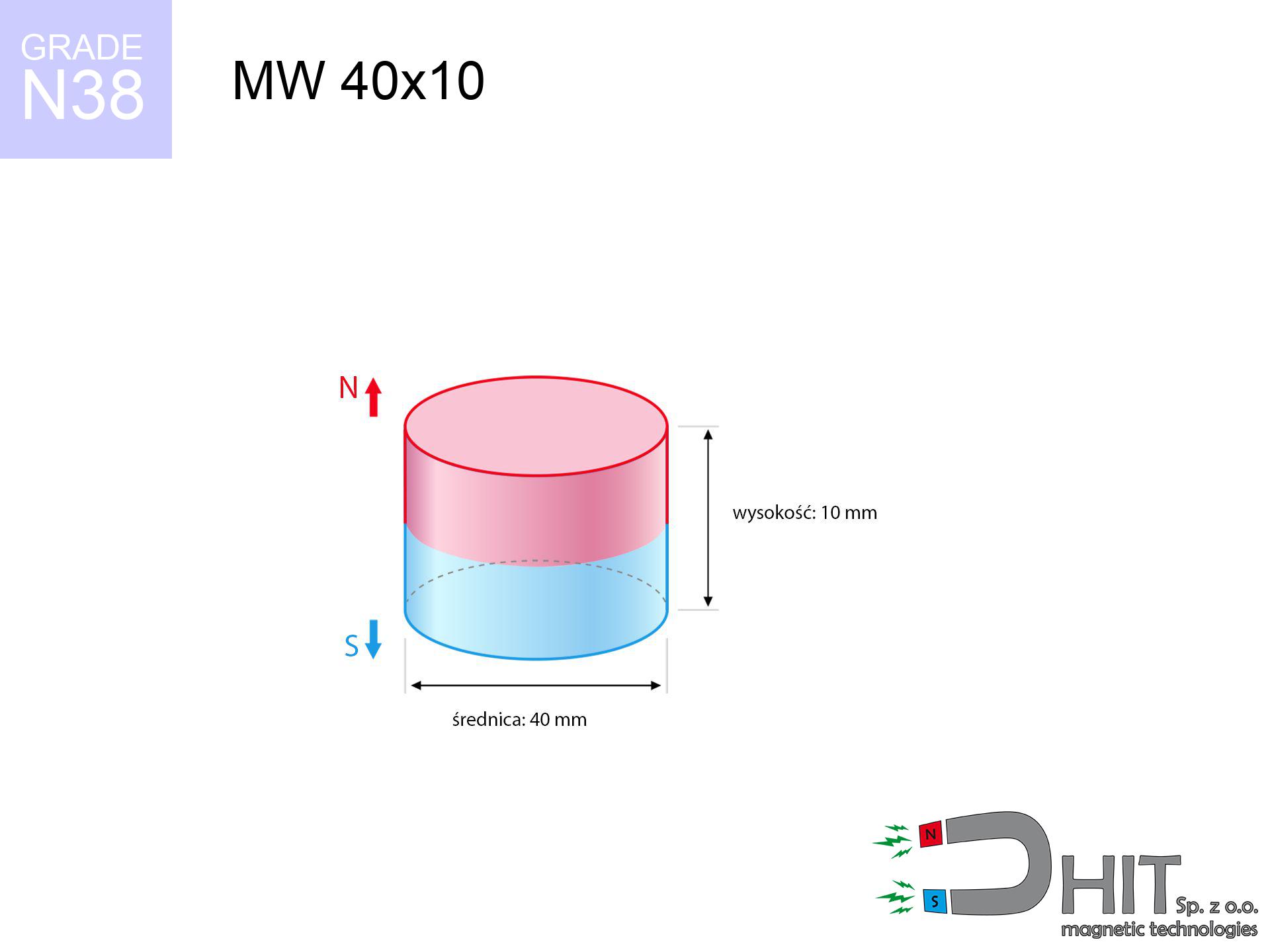
MW 40x10 / N38 - cylindrical magnet
cylindrical magnet
Catalog no 010066
GTIN/EAN: 5906301810650
Diameter Ø
40 mm [±0,1 mm]
Height
10 mm [±0,1 mm]
Weight
94.25 g
Magnetization Direction
↑ axial
Load capacity
27.73 kg / 271.99 N
Magnetic Induction
277.22 mT / 2772 Gs
Coating
[NiCuNi] Nickel
36.57 ZŁ with VAT / pcs + price for transport
29.73 ZŁ net + 23% VAT / pcs
bulk discounts:
Need more?
Give us a call
+48 22 499 98 98
if you prefer get in touch via
inquiry form
through our site.
Lifting power along with form of a neodymium magnet can be reviewed using our
online calculation tool.
Same-day shipping for orders placed before 14:00.
Technical of the product - MW 40x10 / N38 - cylindrical magnet
Specification / characteristics - MW 40x10 / N38 - cylindrical magnet
| properties | values |
|---|---|
| Cat. no. | 010066 |
| GTIN/EAN | 5906301810650 |
| Production/Distribution | Dhit sp. z o.o. |
| Country of origin | Poland / China / Germany |
| Customs code | 85059029 |
| Diameter Ø | 40 mm [±0,1 mm] |
| Height | 10 mm [±0,1 mm] |
| Weight | 94.25 g |
| Magnetization Direction | ↑ axial |
| Load capacity ~ ? | 27.73 kg / 271.99 N |
| Magnetic Induction ~ ? | 277.22 mT / 2772 Gs |
| Coating | [NiCuNi] Nickel |
| Manufacturing Tolerance | ±0.1 mm |
Magnetic properties of material N38
| properties | values | units |
|---|---|---|
| remenance Br [min. - max.] ? | 12.2-12.6 | kGs |
| remenance Br [min. - max.] ? | 1220-1260 | mT |
| coercivity bHc ? | 10.8-11.5 | kOe |
| coercivity bHc ? | 860-915 | kA/m |
| actual internal force iHc | ≥ 12 | kOe |
| actual internal force iHc | ≥ 955 | kA/m |
| energy density [min. - max.] ? | 36-38 | BH max MGOe |
| energy density [min. - max.] ? | 287-303 | BH max KJ/m |
| max. temperature ? | ≤ 80 | °C |
Physical properties of sintered neodymium magnets Nd2Fe14B at 20°C
| properties | values | units |
|---|---|---|
| Vickers hardness | ≥550 | Hv |
| Density | ≥7.4 | g/cm3 |
| Curie Temperature TC | 312 - 380 | °C |
| Curie Temperature TF | 593 - 716 | °F |
| Specific resistance | 150 | μΩ⋅cm |
| Bending strength | 250 | MPa |
| Compressive strength | 1000~1100 | MPa |
| Thermal expansion parallel (∥) to orientation (M) | (3-4) x 10-6 | °C-1 |
| Thermal expansion perpendicular (⊥) to orientation (M) | -(1-3) x 10-6 | °C-1 |
| Young's modulus | 1.7 x 10⁴ | kg/mm² |
Physical analysis of the product - data
Presented data represent the outcome of a mathematical calculation. Values are based on algorithms for the class Nd2Fe14B. Real-world parameters may deviate from the simulation results. Use these data as a supplementary guide for designers.
Table 1: Static force (force vs distance) - power drop
MW 40x10 / N38
| Distance (mm) | Induction (Gauss) / mT | Pull Force (kg/lbs/g/N) | Risk Status |
|---|---|---|---|
| 0 mm |
2772 Gs
277.2 mT
|
27.73 kg / 61.13 pounds
27730.0 g / 272.0 N
|
dangerous! |
| 1 mm |
2678 Gs
267.8 mT
|
25.89 kg / 57.08 pounds
25889.6 g / 254.0 N
|
dangerous! |
| 2 mm |
2573 Gs
257.3 mT
|
23.89 kg / 52.68 pounds
23893.3 g / 234.4 N
|
dangerous! |
| 3 mm |
2459 Gs
245.9 mT
|
21.83 kg / 48.12 pounds
21827.6 g / 214.1 N
|
dangerous! |
| 5 mm |
2216 Gs
221.6 mT
|
17.73 kg / 39.08 pounds
17728.1 g / 173.9 N
|
dangerous! |
| 10 mm |
1611 Gs
161.1 mT
|
9.37 kg / 20.66 pounds
9371.0 g / 91.9 N
|
strong |
| 15 mm |
1121 Gs
112.1 mT
|
4.54 kg / 10.01 pounds
4538.6 g / 44.5 N
|
strong |
| 20 mm |
775 Gs
77.5 mT
|
2.17 kg / 4.77 pounds
2165.8 g / 21.2 N
|
strong |
| 30 mm |
387 Gs
38.7 mT
|
0.54 kg / 1.19 pounds
539.8 g / 5.3 N
|
safe |
| 50 mm |
125 Gs
12.5 mT
|
0.06 kg / 0.12 pounds
56.6 g / 0.6 N
|
safe |
Table 2: Slippage load (wall)
MW 40x10 / N38
| Distance (mm) | Friction coefficient | Pull Force (kg/lbs/g/N) |
|---|---|---|
| 0 mm | Stal (~0.2) |
5.55 kg / 12.23 pounds
5546.0 g / 54.4 N
|
| 1 mm | Stal (~0.2) |
5.18 kg / 11.42 pounds
5178.0 g / 50.8 N
|
| 2 mm | Stal (~0.2) |
4.78 kg / 10.53 pounds
4778.0 g / 46.9 N
|
| 3 mm | Stal (~0.2) |
4.37 kg / 9.63 pounds
4366.0 g / 42.8 N
|
| 5 mm | Stal (~0.2) |
3.55 kg / 7.82 pounds
3546.0 g / 34.8 N
|
| 10 mm | Stal (~0.2) |
1.87 kg / 4.13 pounds
1874.0 g / 18.4 N
|
| 15 mm | Stal (~0.2) |
0.91 kg / 2.00 pounds
908.0 g / 8.9 N
|
| 20 mm | Stal (~0.2) |
0.43 kg / 0.96 pounds
434.0 g / 4.3 N
|
| 30 mm | Stal (~0.2) |
0.11 kg / 0.24 pounds
108.0 g / 1.1 N
|
| 50 mm | Stal (~0.2) |
0.01 kg / 0.03 pounds
12.0 g / 0.1 N
|
Table 3: Wall mounting (sliding) - behavior on slippery surfaces
MW 40x10 / N38
| Surface type | Friction coefficient / % Mocy | Max load (kg/lbs/g/N) |
|---|---|---|
| Raw steel |
µ = 0.3
30% Nominalnej Siły
|
8.32 kg / 18.34 pounds
8319.0 g / 81.6 N
|
| Painted steel (standard) |
µ = 0.2
20% Nominalnej Siły
|
5.55 kg / 12.23 pounds
5546.0 g / 54.4 N
|
| Oily/slippery steel |
µ = 0.1
10% Nominalnej Siły
|
2.77 kg / 6.11 pounds
2773.0 g / 27.2 N
|
| Magnet with anti-slip rubber |
µ = 0.5
50% Nominalnej Siły
|
13.87 kg / 30.57 pounds
13865.0 g / 136.0 N
|
Table 4: Steel thickness (saturation) - sheet metal selection
MW 40x10 / N38
| Steel thickness (mm) | % power | Real pull force (kg/lbs/g/N) |
|---|---|---|
| 0.5 mm |
|
1.39 kg / 3.06 pounds
1386.5 g / 13.6 N
|
| 1 mm |
|
3.47 kg / 7.64 pounds
3466.3 g / 34.0 N
|
| 2 mm |
|
6.93 kg / 15.28 pounds
6932.5 g / 68.0 N
|
| 3 mm |
|
10.40 kg / 22.93 pounds
10398.8 g / 102.0 N
|
| 5 mm |
|
17.33 kg / 38.21 pounds
17331.3 g / 170.0 N
|
| 10 mm |
|
27.73 kg / 61.13 pounds
27730.0 g / 272.0 N
|
| 11 mm |
|
27.73 kg / 61.13 pounds
27730.0 g / 272.0 N
|
| 12 mm |
|
27.73 kg / 61.13 pounds
27730.0 g / 272.0 N
|
Table 5: Working in heat (material behavior) - power drop
MW 40x10 / N38
| Ambient temp. (°C) | Power loss | Remaining pull (kg/lbs/g/N) | Status |
|---|---|---|---|
| 20 °C | 0.0% |
27.73 kg / 61.13 pounds
27730.0 g / 272.0 N
|
OK |
| 40 °C | -2.2% |
27.12 kg / 59.79 pounds
27119.9 g / 266.0 N
|
OK |
| 60 °C | -4.4% |
26.51 kg / 58.44 pounds
26509.9 g / 260.1 N
|
|
| 80 °C | -6.6% |
25.90 kg / 57.10 pounds
25899.8 g / 254.1 N
|
|
| 100 °C | -28.8% |
19.74 kg / 43.53 pounds
19743.8 g / 193.7 N
|
Table 6: Two magnets (repulsion) - field range
MW 40x10 / N38
| Gap (mm) | Attraction (kg/lbs) (N-S) | Lateral Force (kg/lbs/g/N) | Repulsion (kg/lbs) (N-N) |
|---|---|---|---|
| 0 mm |
59.52 kg / 131.22 pounds
4 382 Gs
|
8.93 kg / 19.68 pounds
8928 g / 87.6 N
|
N/A |
| 1 mm |
57.61 kg / 127.01 pounds
5 454 Gs
|
8.64 kg / 19.05 pounds
8642 g / 84.8 N
|
51.85 kg / 114.31 pounds
~0 Gs
|
| 2 mm |
55.57 kg / 122.52 pounds
5 357 Gs
|
8.34 kg / 18.38 pounds
8336 g / 81.8 N
|
50.01 kg / 110.26 pounds
~0 Gs
|
| 3 mm |
53.46 kg / 117.85 pounds
5 254 Gs
|
8.02 kg / 17.68 pounds
8019 g / 78.7 N
|
48.11 kg / 106.07 pounds
~0 Gs
|
| 5 mm |
49.08 kg / 108.20 pounds
5 034 Gs
|
7.36 kg / 16.23 pounds
7362 g / 72.2 N
|
44.17 kg / 97.38 pounds
~0 Gs
|
| 10 mm |
38.05 kg / 83.89 pounds
4 433 Gs
|
5.71 kg / 12.58 pounds
5708 g / 56.0 N
|
34.25 kg / 75.50 pounds
~0 Gs
|
| 20 mm |
20.11 kg / 44.35 pounds
3 223 Gs
|
3.02 kg / 6.65 pounds
3017 g / 29.6 N
|
18.10 kg / 39.91 pounds
~0 Gs
|
| 50 mm |
2.27 kg / 5.01 pounds
1 083 Gs
|
0.34 kg / 0.75 pounds
341 g / 3.3 N
|
2.05 kg / 4.51 pounds
~0 Gs
|
| 60 mm |
1.16 kg / 2.55 pounds
773 Gs
|
0.17 kg / 0.38 pounds
174 g / 1.7 N
|
1.04 kg / 2.30 pounds
~0 Gs
|
| 70 mm |
0.62 kg / 1.36 pounds
565 Gs
|
0.09 kg / 0.20 pounds
93 g / 0.9 N
|
0.56 kg / 1.23 pounds
~0 Gs
|
| 80 mm |
0.35 kg / 0.76 pounds
422 Gs
|
0.05 kg / 0.11 pounds
52 g / 0.5 N
|
0.31 kg / 0.69 pounds
~0 Gs
|
| 90 mm |
0.20 kg / 0.44 pounds
322 Gs
|
0.03 kg / 0.07 pounds
30 g / 0.3 N
|
0.18 kg / 0.40 pounds
~0 Gs
|
| 100 mm |
0.12 kg / 0.27 pounds
251 Gs
|
0.02 kg / 0.04 pounds
18 g / 0.2 N
|
0.11 kg / 0.24 pounds
~0 Gs
|
Table 7: Protective zones (implants) - precautionary measures
MW 40x10 / N38
| Object / Device | Limit (Gauss) / mT | Safe distance |
|---|---|---|
| Pacemaker | 5 Gs (0.5 mT) | 16.5 cm |
| Hearing aid | 10 Gs (1.0 mT) | 13.0 cm |
| Mechanical watch | 20 Gs (2.0 mT) | 10.5 cm |
| Phone / Smartphone | 40 Gs (4.0 mT) | 8.0 cm |
| Remote | 50 Gs (5.0 mT) | 7.5 cm |
| Payment card | 400 Gs (40.0 mT) | 3.0 cm |
| HDD hard drive | 600 Gs (60.0 mT) | 2.5 cm |
Table 8: Collisions (kinetic energy) - collision effects
MW 40x10 / N38
| Start from (mm) | Speed (km/h) | Energy (J) | Predicted outcome |
|---|---|---|---|
| 10 mm |
20.63 km/h
(5.73 m/s)
|
1.55 J | |
| 30 mm |
30.32 km/h
(8.42 m/s)
|
3.34 J | |
| 50 mm |
38.73 km/h
(10.76 m/s)
|
5.45 J | |
| 100 mm |
54.71 km/h
(15.20 m/s)
|
10.88 J |
Table 9: Surface protection spec
MW 40x10 / N38
| Technical parameter | Value / Description |
|---|---|
| Coating type | [NiCuNi] Nickel |
| Layer structure | Nickel - Copper - Nickel |
| Layer thickness | 10-20 µm |
| Salt spray test (SST) ? | 24 h |
| Recommended environment | Indoors only (dry) |
Table 10: Construction data (Flux)
MW 40x10 / N38
| Parameter | Value | SI Unit / Description |
|---|---|---|
| Magnetic Flux | 38 700 Mx | 387.0 µWb |
| Pc Coefficient | 0.35 | Low (Flat) |
Table 11: Submerged application
MW 40x10 / N38
| Environment | Effective steel pull | Effect |
|---|---|---|
| Air (land) | 27.73 kg | Standard |
| Water (riverbed) |
31.75 kg
(+4.02 kg buoyancy gain)
|
+14.5% |
1. Wall mount (shear)
*Warning: On a vertical wall, the magnet retains merely a fraction of its max power.
2. Steel thickness impact
*Thin steel (e.g. 0.5mm PC case) severely reduces the holding force.
3. Heat tolerance
*For standard magnets, the max working temp is 80°C.
4. Demagnetization curve and operating point (B-H)
chart generated for the permeance coefficient Pc (Permeance Coefficient) = 0.35
This simulation demonstrates the magnetic stability of the selected magnet under specific geometric conditions. The solid red line represents the demagnetization curve (material potential), while the dashed blue line is the load line based on the magnet's geometry. The Pc (Permeance Coefficient), also known as the load line slope, is a dimensionless value that describes the relationship between the magnet's shape and its magnetic stability. The intersection of these two lines (the black dot) is the operating point — it determines the actual magnetic flux density generated by the magnet in this specific configuration. A higher Pc value means the magnet is more 'slender' (tall relative to its area), resulting in a higher operating point and better resistance to irreversible demagnetization caused by external fields or temperature. A value of 0.42 is relatively low (typical for flat magnets), meaning the operating point is closer to the 'knee' of the curve — caution is advised when operating at temperatures near the maximum limit to avoid strength loss.
Material specification
| iron (Fe) | 64% – 68% |
| neodymium (Nd) | 29% – 32% |
| boron (B) | 1.1% – 1.2% |
| dysprosium (Dy) | 0.5% – 2.0% |
| coating (Ni-Cu-Ni) | < 0.05% |
Ecology and recycling (GPSR)
| recyclability (EoL) | 100% |
| recycled raw materials | ~10% (pre-cons) |
| carbon footprint | low / zredukowany |
| waste code (EWC) | 16 02 16 |
Other proposals
![UMGGW 22x6 [M4] GW / N38 - magnetic holder rubber internal thread](https://cdn3.dhit.pl/graphics/products/umg-22x6-m4-gw-jek.jpg "UMGGW 22x6 [M4] GW / N38 - magnetic holder rubber internal thread")


Advantages as well as disadvantages of neodymium magnets.
Benefits
- They virtually do not lose strength, because even after ten years the decline in efficiency is only ~1% (based on calculations),
- They retain their magnetic properties even under strong external field,
- The use of an elegant coating of noble metals (nickel, gold, silver) causes the element to look better,
- The surface of neodymium magnets generates a concentrated magnetic field – this is a key feature,
- Through (appropriate) combination of ingredients, they can achieve high thermal strength, enabling functioning at temperatures approaching 230°C and above...
- Thanks to the option of accurate molding and adaptation to custom requirements, magnetic components can be modeled in a wide range of geometric configurations, which expands the range of possible applications,
- Universal use in modern technologies – they are commonly used in HDD drives, electric motors, advanced medical instruments, as well as industrial machines.
- Relatively small size with high pulling force – neodymium magnets offer impressive pulling force in small dimensions, which makes them useful in miniature devices
Disadvantages
- They are fragile upon too strong impacts. To avoid cracks, it is worth protecting magnets in special housings. Such protection not only shields the magnet but also improves its resistance to damage
- Neodymium magnets demagnetize when exposed to high temperatures. After reaching 80°C, many of them experience permanent drop of strength (a factor is the shape as well as dimensions of the magnet). We offer magnets specially adapted to work at temperatures up to 230°C marked [AH], which are very resistant to heat
- Due to the susceptibility of magnets to corrosion in a humid environment, we suggest using waterproof magnets made of rubber, plastic or other material stable to moisture, when using outdoors
- Limited ability of making threads in the magnet and complex forms - recommended is cover - mounting mechanism.
- Possible danger related to microscopic parts of magnets are risky, in case of ingestion, which becomes key in the context of child health protection. Furthermore, small components of these magnets are able to disrupt the diagnostic process medical when they are in the body.
- High unit price – neodymium magnets are more expensive than other types of magnets (e.g. ferrite), which increases costs of application in large quantities
Pull force analysis
Maximum lifting capacity of the magnet – what contributes to it?
- using a plate made of low-carbon steel, serving as a magnetic yoke
- with a cross-section no less than 10 mm
- with an ground touching surface
- under conditions of gap-free contact (surface-to-surface)
- during pulling in a direction perpendicular to the plane
- at ambient temperature room level
Practical aspects of lifting capacity – factors
- Space between surfaces – every millimeter of separation (caused e.g. by veneer or dirt) drastically reduces the pulling force, often by half at just 0.5 mm.
- Load vector – maximum parameter is reached only during pulling at a 90° angle. The resistance to sliding of the magnet along the surface is usually many times lower (approx. 1/5 of the lifting capacity).
- Plate thickness – insufficiently thick steel does not accept the full field, causing part of the power to be wasted into the air.
- Steel type – mild steel gives the best results. Alloy admixtures lower magnetic properties and lifting capacity.
- Smoothness – ideal contact is obtained only on polished steel. Any scratches and bumps reduce the real contact area, weakening the magnet.
- Heat – neodymium magnets have a sensitivity to temperature. When it is hot they are weaker, and in frost they can be stronger (up to a certain limit).
Lifting capacity was measured by applying a polished steel plate of optimal thickness (min. 20 mm), under perpendicular detachment force, in contrast under attempts to slide the magnet the holding force is lower. In addition, even a minimal clearance between the magnet and the plate reduces the lifting capacity.
H&S for magnets
Mechanical processing
Machining of neodymium magnets carries a risk of fire risk. Magnetic powder reacts violently with oxygen and is hard to extinguish.
Nickel coating and allergies
Warning for allergy sufferers: The nickel-copper-nickel coating consists of nickel. If redness appears, immediately stop working with magnets and wear gloves.
Precision electronics
A strong magnetic field interferes with the operation of compasses in phones and GPS navigation. Do not bring magnets close to a device to avoid damaging the sensors.
Pacemakers
Medical warning: Neodymium magnets can deactivate heart devices and defibrillators. Do not approach if you have electronic implants.
Do not overheat magnets
Keep cool. NdFeB magnets are susceptible to heat. If you require resistance above 80°C, ask us about HT versions (H, SH, UH).
Bone fractures
Big blocks can crush fingers instantly. Do not place your hand betwixt two strong magnets.
Risk of cracking
NdFeB magnets are ceramic materials, which means they are prone to chipping. Collision of two magnets leads to them breaking into shards.
This is not a toy
Absolutely store magnets out of reach of children. Ingestion danger is high, and the consequences of magnets connecting inside the body are tragic.
Keep away from computers
Powerful magnetic fields can erase data on credit cards, HDDs, and other magnetic media. Stay away of min. 10 cm.
Respect the power
Before starting, read the rules. Sudden snapping can destroy the magnet or hurt your hand. Think ahead.
Tabela kosztu i czasu dostawy
Płatność przed wysyłką:

GLS kurier
Przesyłka będzie u Ciebie za 2-3 dni
14.99 ZŁ

InPost Paczkomaty 24/7
Przesyłka będzie u Ciebie za 1-2 dni
12.30 ZŁ
Płatność przy odbiorze (pobranie):
GLS kurier
Przesyłka będzie u Ciebie za 1-2 dni
23.00 ZŁ
Rate the product
Your rating