
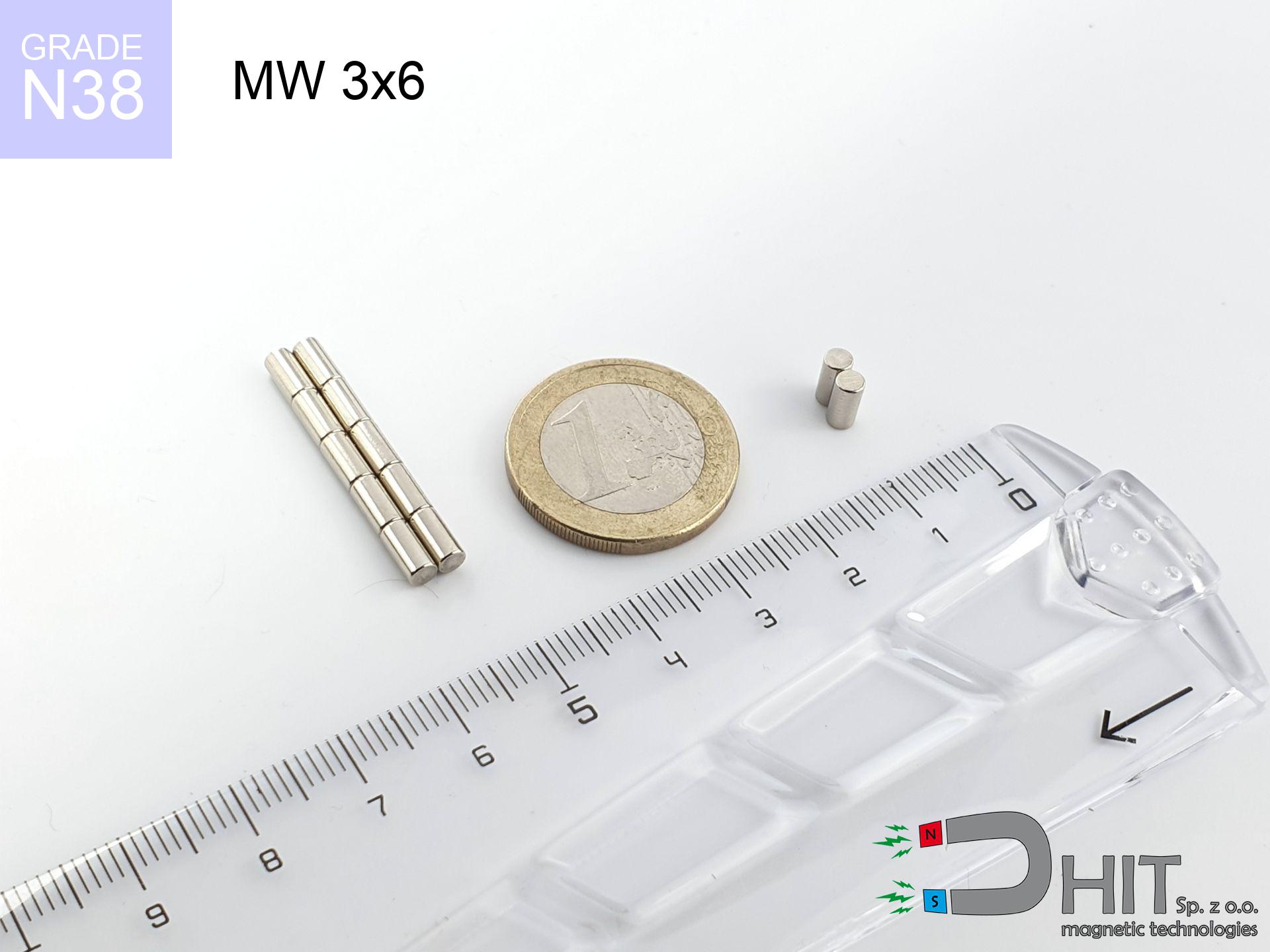
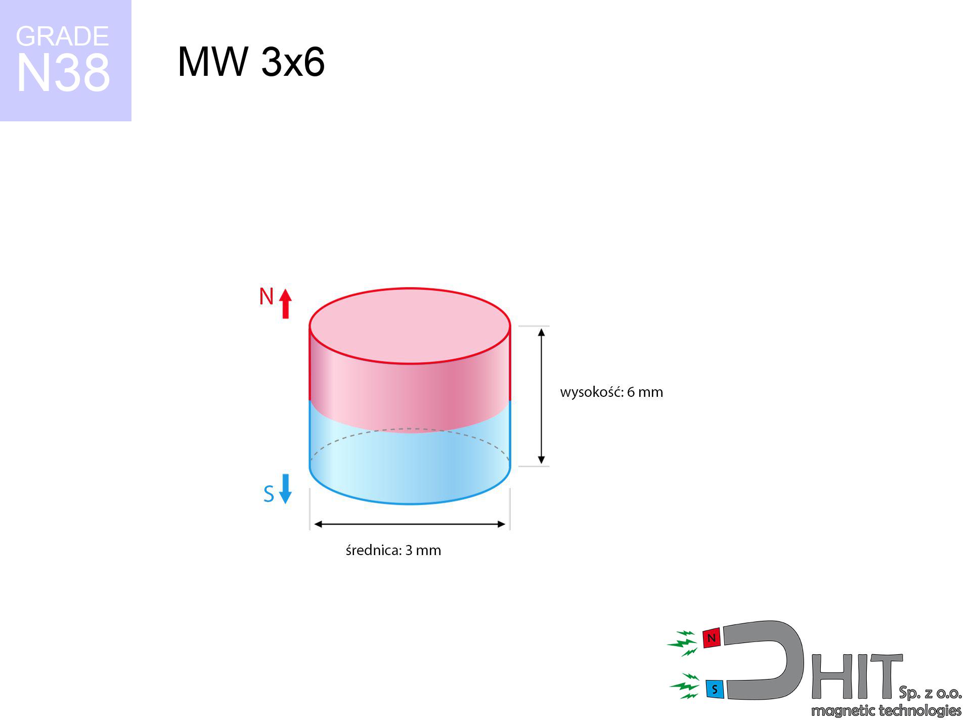
MW 3x6 / N38 - cylindrical magnet
cylindrical magnet
Catalog no 010065
GTIN/EAN: 5906301810643
Diameter Ø
3 mm [±0,1 mm]
Height
6 mm [±0,1 mm]
Weight
0.32 g
Magnetization Direction
↑ axial
Load capacity
0.20 kg / 1.95 N
Magnetic Induction
598.96 mT / 5990 Gs
Coating
[NiCuNi] Nickel
0.295 ZŁ with VAT / pcs + price for transport
0.240 ZŁ net + 23% VAT / pcs
bulk discounts:
Need more?
Pick up the phone and ask
+48 22 499 98 98
or send us a note using
inquiry form
the contact form page.
Weight as well as structure of a magnet can be analyzed using our
force calculator.
Same-day shipping for orders placed before 14:00.
Technical data of the product - MW 3x6 / N38 - cylindrical magnet
Specification / characteristics - MW 3x6 / N38 - cylindrical magnet
| properties | values |
|---|---|
| Cat. no. | 010065 |
| GTIN/EAN | 5906301810643 |
| Production/Distribution | Dhit sp. z o.o. |
| Country of origin | Poland / China / Germany |
| Customs code | 85059029 |
| Diameter Ø | 3 mm [±0,1 mm] |
| Height | 6 mm [±0,1 mm] |
| Weight | 0.32 g |
| Magnetization Direction | ↑ axial |
| Load capacity ~ ? | 0.20 kg / 1.95 N |
| Magnetic Induction ~ ? | 598.96 mT / 5990 Gs |
| Coating | [NiCuNi] Nickel |
| Manufacturing Tolerance | ±0.1 mm |
Magnetic properties of material N38
| properties | values | units |
|---|---|---|
| remenance Br [min. - max.] ? | 12.2-12.6 | kGs |
| remenance Br [min. - max.] ? | 1220-1260 | mT |
| coercivity bHc ? | 10.8-11.5 | kOe |
| coercivity bHc ? | 860-915 | kA/m |
| actual internal force iHc | ≥ 12 | kOe |
| actual internal force iHc | ≥ 955 | kA/m |
| energy density [min. - max.] ? | 36-38 | BH max MGOe |
| energy density [min. - max.] ? | 287-303 | BH max KJ/m |
| max. temperature ? | ≤ 80 | °C |
Physical properties of sintered neodymium magnets Nd2Fe14B at 20°C
| properties | values | units |
|---|---|---|
| Vickers hardness | ≥550 | Hv |
| Density | ≥7.4 | g/cm3 |
| Curie Temperature TC | 312 - 380 | °C |
| Curie Temperature TF | 593 - 716 | °F |
| Specific resistance | 150 | μΩ⋅cm |
| Bending strength | 250 | MPa |
| Compressive strength | 1000~1100 | MPa |
| Thermal expansion parallel (∥) to orientation (M) | (3-4) x 10-6 | °C-1 |
| Thermal expansion perpendicular (⊥) to orientation (M) | -(1-3) x 10-6 | °C-1 |
| Young's modulus | 1.7 x 10⁴ | kg/mm² |
Physical modeling of the assembly - technical parameters
Presented values represent the result of a physical calculation. Results rely on algorithms for the class Nd2Fe14B. Actual conditions might slightly differ. Please consider these data as a reference point during assembly planning.
Table 1: Static pull force (pull vs gap) - interaction chart
MW 3x6 / N38
| Distance (mm) | Induction (Gauss) / mT | Pull Force (kg/lbs/g/N) | Risk Status |
|---|---|---|---|
| 0 mm |
5974 Gs
597.4 mT
|
0.20 kg / 0.44 LBS
200.0 g / 2.0 N
|
low risk |
| 1 mm |
2623 Gs
262.3 mT
|
0.04 kg / 0.09 LBS
38.6 g / 0.4 N
|
low risk |
| 2 mm |
1134 Gs
113.4 mT
|
0.01 kg / 0.02 LBS
7.2 g / 0.1 N
|
low risk |
| 3 mm |
570 Gs
57.0 mT
|
0.00 kg / 0.00 LBS
1.8 g / 0.0 N
|
low risk |
| 5 mm |
205 Gs
20.5 mT
|
0.00 kg / 0.00 LBS
0.2 g / 0.0 N
|
low risk |
| 10 mm |
42 Gs
4.2 mT
|
0.00 kg / 0.00 LBS
0.0 g / 0.0 N
|
low risk |
| 15 mm |
15 Gs
1.5 mT
|
0.00 kg / 0.00 LBS
0.0 g / 0.0 N
|
low risk |
| 20 mm |
7 Gs
0.7 mT
|
0.00 kg / 0.00 LBS
0.0 g / 0.0 N
|
low risk |
| 30 mm |
2 Gs
0.2 mT
|
0.00 kg / 0.00 LBS
0.0 g / 0.0 N
|
low risk |
| 50 mm |
1 Gs
0.1 mT
|
0.00 kg / 0.00 LBS
0.0 g / 0.0 N
|
low risk |
Table 2: Sliding load (vertical surface)
MW 3x6 / N38
| Distance (mm) | Friction coefficient | Pull Force (kg/lbs/g/N) |
|---|---|---|
| 0 mm | Stal (~0.2) |
0.04 kg / 0.09 LBS
40.0 g / 0.4 N
|
| 1 mm | Stal (~0.2) |
0.01 kg / 0.02 LBS
8.0 g / 0.1 N
|
| 2 mm | Stal (~0.2) |
0.00 kg / 0.00 LBS
2.0 g / 0.0 N
|
| 3 mm | Stal (~0.2) |
0.00 kg / 0.00 LBS
0.0 g / 0.0 N
|
| 5 mm | Stal (~0.2) |
0.00 kg / 0.00 LBS
0.0 g / 0.0 N
|
| 10 mm | Stal (~0.2) |
0.00 kg / 0.00 LBS
0.0 g / 0.0 N
|
| 15 mm | Stal (~0.2) |
0.00 kg / 0.00 LBS
0.0 g / 0.0 N
|
| 20 mm | Stal (~0.2) |
0.00 kg / 0.00 LBS
0.0 g / 0.0 N
|
| 30 mm | Stal (~0.2) |
0.00 kg / 0.00 LBS
0.0 g / 0.0 N
|
| 50 mm | Stal (~0.2) |
0.00 kg / 0.00 LBS
0.0 g / 0.0 N
|
Table 3: Vertical assembly (sliding) - vertical pull
MW 3x6 / N38
| Surface type | Friction coefficient / % Mocy | Max load (kg/lbs/g/N) |
|---|---|---|
| Raw steel |
µ = 0.3
30% Nominalnej Siły
|
0.06 kg / 0.13 LBS
60.0 g / 0.6 N
|
| Painted steel (standard) |
µ = 0.2
20% Nominalnej Siły
|
0.04 kg / 0.09 LBS
40.0 g / 0.4 N
|
| Oily/slippery steel |
µ = 0.1
10% Nominalnej Siły
|
0.02 kg / 0.04 LBS
20.0 g / 0.2 N
|
| Magnet with anti-slip rubber |
µ = 0.5
50% Nominalnej Siły
|
0.10 kg / 0.22 LBS
100.0 g / 1.0 N
|
Table 4: Steel thickness (substrate influence) - power losses
MW 3x6 / N38
| Steel thickness (mm) | % power | Real pull force (kg/lbs/g/N) |
|---|---|---|
| 0.5 mm |
|
0.02 kg / 0.04 LBS
20.0 g / 0.2 N
|
| 1 mm |
|
0.05 kg / 0.11 LBS
50.0 g / 0.5 N
|
| 2 mm |
|
0.10 kg / 0.22 LBS
100.0 g / 1.0 N
|
| 3 mm |
|
0.15 kg / 0.33 LBS
150.0 g / 1.5 N
|
| 5 mm |
|
0.20 kg / 0.44 LBS
200.0 g / 2.0 N
|
| 10 mm |
|
0.20 kg / 0.44 LBS
200.0 g / 2.0 N
|
| 11 mm |
|
0.20 kg / 0.44 LBS
200.0 g / 2.0 N
|
| 12 mm |
|
0.20 kg / 0.44 LBS
200.0 g / 2.0 N
|
Table 5: Working in heat (stability) - power drop
MW 3x6 / N38
| Ambient temp. (°C) | Power loss | Remaining pull (kg/lbs/g/N) | Status |
|---|---|---|---|
| 20 °C | 0.0% |
0.20 kg / 0.44 LBS
200.0 g / 2.0 N
|
OK |
| 40 °C | -2.2% |
0.20 kg / 0.43 LBS
195.6 g / 1.9 N
|
OK |
| 60 °C | -4.4% |
0.19 kg / 0.42 LBS
191.2 g / 1.9 N
|
OK |
| 80 °C | -6.6% |
0.19 kg / 0.41 LBS
186.8 g / 1.8 N
|
|
| 100 °C | -28.8% |
0.14 kg / 0.31 LBS
142.4 g / 1.4 N
|
Table 6: Two magnets (attraction) - field range
MW 3x6 / N38
| Gap (mm) | Attraction (kg/lbs) (N-S) | Lateral Force (kg/lbs/g/N) | Repulsion (kg/lbs) (N-N) |
|---|---|---|---|
| 0 mm |
1.56 kg / 3.43 LBS
6 111 Gs
|
0.23 kg / 0.51 LBS
233 g / 2.3 N
|
N/A |
| 1 mm |
0.73 kg / 1.60 LBS
8 161 Gs
|
0.11 kg / 0.24 LBS
109 g / 1.1 N
|
0.65 kg / 1.44 LBS
~0 Gs
|
| 2 mm |
0.30 kg / 0.66 LBS
5 246 Gs
|
0.04 kg / 0.10 LBS
45 g / 0.4 N
|
0.27 kg / 0.60 LBS
~0 Gs
|
| 3 mm |
0.13 kg / 0.28 LBS
3 391 Gs
|
0.02 kg / 0.04 LBS
19 g / 0.2 N
|
0.11 kg / 0.25 LBS
~0 Gs
|
| 5 mm |
0.03 kg / 0.06 LBS
1 578 Gs
|
0.00 kg / 0.01 LBS
4 g / 0.0 N
|
0.02 kg / 0.05 LBS
~0 Gs
|
| 10 mm |
0.00 kg / 0.00 LBS
409 Gs
|
0.00 kg / 0.00 LBS
0 g / 0.0 N
|
0.00 kg / 0.00 LBS
~0 Gs
|
| 20 mm |
0.00 kg / 0.00 LBS
83 Gs
|
0.00 kg / 0.00 LBS
0 g / 0.0 N
|
0.00 kg / 0.00 LBS
~0 Gs
|
| 50 mm |
0.00 kg / 0.00 LBS
8 Gs
|
0.00 kg / 0.00 LBS
0 g / 0.0 N
|
0.00 kg / 0.00 LBS
~0 Gs
|
| 60 mm |
0.00 kg / 0.00 LBS
5 Gs
|
0.00 kg / 0.00 LBS
0 g / 0.0 N
|
0.00 kg / 0.00 LBS
~0 Gs
|
| 70 mm |
0.00 kg / 0.00 LBS
3 Gs
|
0.00 kg / 0.00 LBS
0 g / 0.0 N
|
0.00 kg / 0.00 LBS
~0 Gs
|
| 80 mm |
0.00 kg / 0.00 LBS
2 Gs
|
0.00 kg / 0.00 LBS
0 g / 0.0 N
|
0.00 kg / 0.00 LBS
~0 Gs
|
| 90 mm |
0.00 kg / 0.00 LBS
2 Gs
|
0.00 kg / 0.00 LBS
0 g / 0.0 N
|
0.00 kg / 0.00 LBS
~0 Gs
|
| 100 mm |
0.00 kg / 0.00 LBS
1 Gs
|
0.00 kg / 0.00 LBS
0 g / 0.0 N
|
0.00 kg / 0.00 LBS
~0 Gs
|
Table 7: Protective zones (implants) - warnings
MW 3x6 / N38
| Object / Device | Limit (Gauss) / mT | Safe distance |
|---|---|---|
| Pacemaker | 5 Gs (0.5 mT) | 2.5 cm |
| Hearing aid | 10 Gs (1.0 mT) | 2.0 cm |
| Timepiece | 20 Gs (2.0 mT) | 1.5 cm |
| Mobile device | 40 Gs (4.0 mT) | 1.5 cm |
| Remote | 50 Gs (5.0 mT) | 1.0 cm |
| Payment card | 400 Gs (40.0 mT) | 0.5 cm |
| HDD hard drive | 600 Gs (60.0 mT) | 0.5 cm |
Table 8: Collisions (cracking risk) - collision effects
MW 3x6 / N38
| Start from (mm) | Speed (km/h) | Energy (J) | Predicted outcome |
|---|---|---|---|
| 10 mm |
25.21 km/h
(7.00 m/s)
|
0.01 J | |
| 30 mm |
43.67 km/h
(12.13 m/s)
|
0.02 J | |
| 50 mm |
56.38 km/h
(15.66 m/s)
|
0.04 J | |
| 100 mm |
79.73 km/h
(22.15 m/s)
|
0.08 J |
Table 9: Corrosion resistance
MW 3x6 / N38
| Technical parameter | Value / Description |
|---|---|
| Coating type | [NiCuNi] Nickel |
| Layer structure | Nickel - Copper - Nickel |
| Layer thickness | 10-20 µm |
| Salt spray test (SST) ? | 24 h |
| Recommended environment | Indoors only (dry) |
Table 10: Electrical data (Flux)
MW 3x6 / N38
| Parameter | Value | SI Unit / Description |
|---|---|---|
| Magnetic Flux | 470 Mx | 4.7 µWb |
| Pc Coefficient | 1.21 | High (Stable) |
Table 11: Hydrostatics and buoyancy
MW 3x6 / N38
| Environment | Effective steel pull | Effect |
|---|---|---|
| Air (land) | 0.20 kg | Standard |
| Water (riverbed) |
0.23 kg
(+0.03 kg buoyancy gain)
|
+14.5% |
1. Sliding resistance
*Warning: On a vertical wall, the magnet holds only a fraction of its nominal pull.
2. Plate thickness effect
*Thin metal sheet (e.g. computer case) severely limits the holding force.
3. Power loss vs temp
*For standard magnets, the critical limit is 80°C.
4. Demagnetization curve and operating point (B-H)
chart generated for the permeance coefficient Pc (Permeance Coefficient) = 1.21
The chart above illustrates the magnetic characteristics of the material within the second quadrant of the hysteresis loop. The solid red line represents the demagnetization curve (material potential), while the dashed blue line is the load line based on the magnet's geometry. The Pc (Permeance Coefficient), also known as the load line slope, is a dimensionless value that describes the relationship between the magnet's shape and its magnetic stability. The intersection of these two lines (the black dot) is the operating point — it determines the actual magnetic flux density generated by the magnet in this specific configuration. A higher Pc value means the magnet is more 'slender' (tall relative to its area), resulting in a higher operating point and better resistance to irreversible demagnetization caused by external fields or temperature. A value of 0.42 is relatively low (typical for flat magnets), meaning the operating point is closer to the 'knee' of the curve — caution is advised when operating at temperatures near the maximum limit to avoid strength loss.
Material specification
| iron (Fe) | 64% – 68% |
| neodymium (Nd) | 29% – 32% |
| boron (B) | 1.1% – 1.2% |
| dysprosium (Dy) | 0.5% – 2.0% |
| coating (Ni-Cu-Ni) | < 0.05% |
Ecology and recycling (GPSR)
| recyclability (EoL) | 100% |
| recycled raw materials | ~10% (pre-cons) |
| carbon footprint | low / zredukowany |
| waste code (EWC) | 16 02 16 |
View more proposals


Pros and cons of Nd2Fe14B magnets.
Pros
- Their strength is maintained, and after around ten years it drops only by ~1% (theoretically),
- Neodymium magnets remain extremely resistant to demagnetization caused by external interference,
- Thanks to the shiny finish, the layer of Ni-Cu-Ni, gold-plated, or silver-plated gives an aesthetic appearance,
- Neodymium magnets achieve maximum magnetic induction on a small area, which ensures high operational effectiveness,
- Neodymium magnets are characterized by extremely high magnetic induction on the magnet surface and can work (depending on the shape) even at a temperature of 230°C or more...
- Thanks to modularity in constructing and the ability to modify to client solutions,
- Huge importance in high-tech industry – they are utilized in magnetic memories, electric drive systems, medical devices, also multitasking production systems.
- Compactness – despite small sizes they offer powerful magnetic field, making them ideal for precision applications
Cons
- At strong impacts they can crack, therefore we advise placing them in steel cases. A metal housing provides additional protection against damage, as well as increases the magnet's durability.
- Neodymium magnets decrease their force under the influence of heating. As soon as 80°C is exceeded, many of them start losing their power. Therefore, we recommend our special magnets marked [AH], which maintain durability even at temperatures up to 230°C
- They oxidize in a humid environment. For use outdoors we suggest using waterproof magnets e.g. in rubber, plastic
- Limited ability of making threads in the magnet and complex shapes - preferred is a housing - magnetic holder.
- Potential hazard resulting from small fragments of magnets can be dangerous, if swallowed, which gains importance in the context of child health protection. Furthermore, small components of these products are able to disrupt the diagnostic process medical when they are in the body.
- Higher cost of purchase is a significant factor to consider compared to ceramic magnets, especially in budget applications
Pull force analysis
Maximum magnetic pulling force – what contributes to it?
- using a sheet made of low-carbon steel, serving as a ideal flux conductor
- whose thickness is min. 10 mm
- with a surface free of scratches
- without the slightest air gap between the magnet and steel
- under axial force direction (90-degree angle)
- at conditions approx. 20°C
Lifting capacity in practice – influencing factors
- Gap between magnet and steel – every millimeter of separation (caused e.g. by veneer or dirt) significantly weakens the magnet efficiency, often by half at just 0.5 mm.
- Load vector – maximum parameter is reached only during perpendicular pulling. The force required to slide of the magnet along the plate is usually several times lower (approx. 1/5 of the lifting capacity).
- Substrate thickness – to utilize 100% power, the steel must be adequately massive. Paper-thin metal restricts the attraction force (the magnet "punches through" it).
- Plate material – mild steel attracts best. Alloy admixtures decrease magnetic properties and holding force.
- Smoothness – ideal contact is obtained only on polished steel. Any scratches and bumps create air cushions, reducing force.
- Temperature influence – hot environment weakens pulling force. Too high temperature can permanently demagnetize the magnet.
Lifting capacity testing was performed on plates with a smooth surface of optimal thickness, under perpendicular forces, in contrast under shearing force the holding force is lower. Additionally, even a small distance between the magnet’s surface and the plate lowers the load capacity.
Warnings
Material brittleness
Watch out for shards. Magnets can fracture upon violent connection, ejecting shards into the air. We recommend safety glasses.
Heat sensitivity
Watch the temperature. Heating the magnet to high heat will destroy its properties and strength.
Immense force
Handle magnets consciously. Their immense force can shock even experienced users. Be vigilant and respect their power.
Pinching danger
Danger of trauma: The attraction force is so great that it can cause hematomas, pinching, and even bone fractures. Protective gloves are recommended.
Implant safety
Health Alert: Neodymium magnets can turn off heart devices and defibrillators. Do not approach if you have medical devices.
Fire risk
Dust produced during cutting of magnets is flammable. Do not drill into magnets unless you are an expert.
Danger to the youngest
These products are not suitable for play. Swallowing a few magnets may result in them attracting across intestines, which constitutes a critical condition and necessitates urgent medical intervention.
Avoid contact if allergic
Studies show that nickel (standard magnet coating) is a common allergen. If your skin reacts to metals, prevent direct skin contact and select versions in plastic housing.
Impact on smartphones
Navigation devices and smartphones are highly susceptible to magnetic fields. Direct contact with a strong magnet can decalibrate the sensors in your phone.
Magnetic media
Powerful magnetic fields can destroy records on payment cards, HDDs, and storage devices. Stay away of min. 10 cm.
Tabela kosztu i czasu dostawy
Płatność przed wysyłką:

GLS kurier
Przesyłka będzie u Ciebie za 2-3 dni
14.99 ZŁ

InPost Paczkomaty 24/7
Przesyłka będzie u Ciebie za 1-2 dni
12.30 ZŁ
Płatność przy odbiorze (pobranie):
GLS kurier
Przesyłka będzie u Ciebie za 1-2 dni
23.00 ZŁ
Rate the product
Your rating