

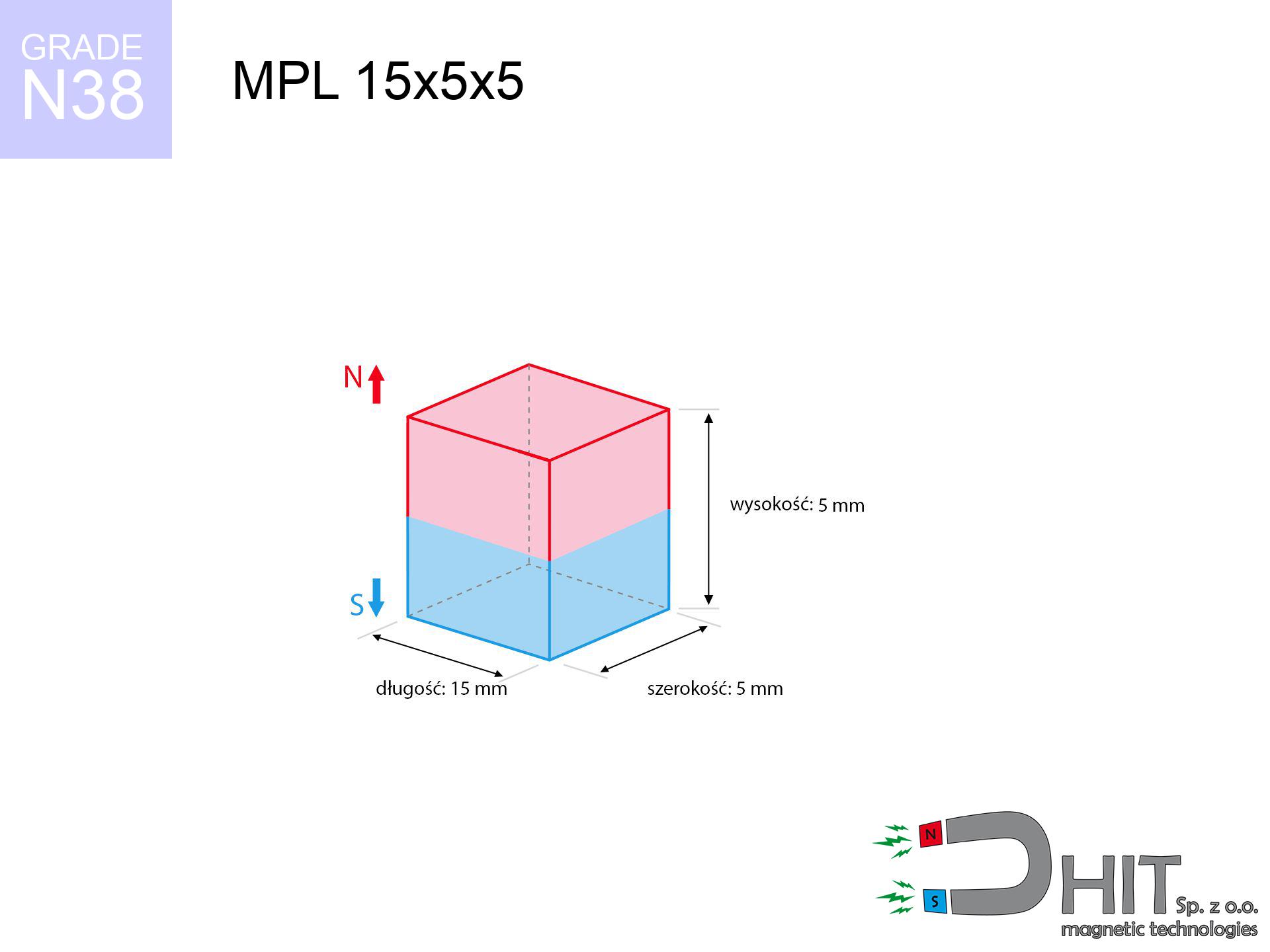
MPL 15x5x5 / N38 - lamellar magnet
lamellar magnet
Catalog no 020123
GTIN/EAN: 5906301811299
length
15 mm [±0,1 mm]
Width
5 mm [±0,1 mm]
Height
5 mm [±0,1 mm]
Weight
2.81 g
Magnetization Direction
↑ axial
Load capacity
3.20 kg / 31.38 N
Magnetic Induction
468.69 mT / 4687 Gs
Coating
[NiCuNi] Nickel
1.390 ZŁ with VAT / pcs + price for transport
1.130 ZŁ net + 23% VAT / pcs
bulk discounts:
Need more?
Pick up the phone and ask
+48 888 99 98 98
alternatively let us know using
our online form
our website.
Parameters and shape of magnetic components can be estimated with our
magnetic mass calculator.
Orders placed before 14:00 will be shipped the same business day.
Technical - MPL 15x5x5 / N38 - lamellar magnet
Specification / characteristics - MPL 15x5x5 / N38 - lamellar magnet
| properties | values |
|---|---|
| Cat. no. | 020123 |
| GTIN/EAN | 5906301811299 |
| Production/Distribution | Dhit sp. z o.o. |
| Country of origin | Poland / China / Germany |
| Customs code | 85059029 |
| length | 15 mm [±0,1 mm] |
| Width | 5 mm [±0,1 mm] |
| Height | 5 mm [±0,1 mm] |
| Weight | 2.81 g |
| Magnetization Direction | ↑ axial |
| Load capacity ~ ? | 3.20 kg / 31.38 N |
| Magnetic Induction ~ ? | 468.69 mT / 4687 Gs |
| Coating | [NiCuNi] Nickel |
| Manufacturing Tolerance | ±0.1 mm |
Magnetic properties of material N38
| properties | values | units |
|---|---|---|
| remenance Br [min. - max.] ? | 12.2-12.6 | kGs |
| remenance Br [min. - max.] ? | 1220-1260 | mT |
| coercivity bHc ? | 10.8-11.5 | kOe |
| coercivity bHc ? | 860-915 | kA/m |
| actual internal force iHc | ≥ 12 | kOe |
| actual internal force iHc | ≥ 955 | kA/m |
| energy density [min. - max.] ? | 36-38 | BH max MGOe |
| energy density [min. - max.] ? | 287-303 | BH max KJ/m |
| max. temperature ? | ≤ 80 | °C |
Physical properties of sintered neodymium magnets Nd2Fe14B at 20°C
| properties | values | units |
|---|---|---|
| Vickers hardness | ≥550 | Hv |
| Density | ≥7.4 | g/cm3 |
| Curie Temperature TC | 312 - 380 | °C |
| Curie Temperature TF | 593 - 716 | °F |
| Specific resistance | 150 | μΩ⋅cm |
| Bending strength | 250 | MPa |
| Compressive strength | 1000~1100 | MPa |
| Thermal expansion parallel (∥) to orientation (M) | (3-4) x 10-6 | °C-1 |
| Thermal expansion perpendicular (⊥) to orientation (M) | -(1-3) x 10-6 | °C-1 |
| Young's modulus | 1.7 x 10⁴ | kg/mm² |
Engineering analysis of the assembly - data
The following data are the direct effect of a engineering simulation. Values rely on models for the class Nd2Fe14B. Operational conditions might slightly deviate from the simulation results. Treat these data as a supplementary guide during assembly planning.
Table 1: Static pull force (force vs gap) - characteristics
MPL 15x5x5 / N38
| Distance (mm) | Induction (Gauss) / mT | Pull Force (kg/lbs/g/N) | Risk Status |
|---|---|---|---|
| 0 mm |
4682 Gs
468.2 mT
|
3.20 kg / 7.05 lbs
3200.0 g / 31.4 N
|
strong |
| 1 mm |
3410 Gs
341.0 mT
|
1.70 kg / 3.74 lbs
1697.3 g / 16.7 N
|
safe |
| 2 mm |
2394 Gs
239.4 mT
|
0.84 kg / 1.84 lbs
836.5 g / 8.2 N
|
safe |
| 3 mm |
1701 Gs
170.1 mT
|
0.42 kg / 0.93 lbs
422.6 g / 4.1 N
|
safe |
| 5 mm |
928 Gs
92.8 mT
|
0.13 kg / 0.28 lbs
125.8 g / 1.2 N
|
safe |
| 10 mm |
286 Gs
28.6 mT
|
0.01 kg / 0.03 lbs
11.9 g / 0.1 N
|
safe |
| 15 mm |
119 Gs
11.9 mT
|
0.00 kg / 0.00 lbs
2.0 g / 0.0 N
|
safe |
| 20 mm |
59 Gs
5.9 mT
|
0.00 kg / 0.00 lbs
0.5 g / 0.0 N
|
safe |
| 30 mm |
21 Gs
2.1 mT
|
0.00 kg / 0.00 lbs
0.1 g / 0.0 N
|
safe |
| 50 mm |
5 Gs
0.5 mT
|
0.00 kg / 0.00 lbs
0.0 g / 0.0 N
|
safe |
Table 2: Shear load (wall)
MPL 15x5x5 / N38
| Distance (mm) | Friction coefficient | Pull Force (kg/lbs/g/N) |
|---|---|---|
| 0 mm | Stal (~0.2) |
0.64 kg / 1.41 lbs
640.0 g / 6.3 N
|
| 1 mm | Stal (~0.2) |
0.34 kg / 0.75 lbs
340.0 g / 3.3 N
|
| 2 mm | Stal (~0.2) |
0.17 kg / 0.37 lbs
168.0 g / 1.6 N
|
| 3 mm | Stal (~0.2) |
0.08 kg / 0.19 lbs
84.0 g / 0.8 N
|
| 5 mm | Stal (~0.2) |
0.03 kg / 0.06 lbs
26.0 g / 0.3 N
|
| 10 mm | Stal (~0.2) |
0.00 kg / 0.00 lbs
2.0 g / 0.0 N
|
| 15 mm | Stal (~0.2) |
0.00 kg / 0.00 lbs
0.0 g / 0.0 N
|
| 20 mm | Stal (~0.2) |
0.00 kg / 0.00 lbs
0.0 g / 0.0 N
|
| 30 mm | Stal (~0.2) |
0.00 kg / 0.00 lbs
0.0 g / 0.0 N
|
| 50 mm | Stal (~0.2) |
0.00 kg / 0.00 lbs
0.0 g / 0.0 N
|
Table 3: Vertical assembly (shearing) - behavior on slippery surfaces
MPL 15x5x5 / N38
| Surface type | Friction coefficient / % Mocy | Max load (kg/lbs/g/N) |
|---|---|---|
| Raw steel |
µ = 0.3
30% Nominalnej Siły
|
0.96 kg / 2.12 lbs
960.0 g / 9.4 N
|
| Painted steel (standard) |
µ = 0.2
20% Nominalnej Siły
|
0.64 kg / 1.41 lbs
640.0 g / 6.3 N
|
| Oily/slippery steel |
µ = 0.1
10% Nominalnej Siły
|
0.32 kg / 0.71 lbs
320.0 g / 3.1 N
|
| Magnet with anti-slip rubber |
µ = 0.5
50% Nominalnej Siły
|
1.60 kg / 3.53 lbs
1600.0 g / 15.7 N
|
Table 4: Material efficiency (saturation) - sheet metal selection
MPL 15x5x5 / N38
| Steel thickness (mm) | % power | Real pull force (kg/lbs/g/N) |
|---|---|---|
| 0.5 mm |
|
0.32 kg / 0.71 lbs
320.0 g / 3.1 N
|
| 1 mm |
|
0.80 kg / 1.76 lbs
800.0 g / 7.8 N
|
| 2 mm |
|
1.60 kg / 3.53 lbs
1600.0 g / 15.7 N
|
| 3 mm |
|
2.40 kg / 5.29 lbs
2400.0 g / 23.5 N
|
| 5 mm |
|
3.20 kg / 7.05 lbs
3200.0 g / 31.4 N
|
| 10 mm |
|
3.20 kg / 7.05 lbs
3200.0 g / 31.4 N
|
| 11 mm |
|
3.20 kg / 7.05 lbs
3200.0 g / 31.4 N
|
| 12 mm |
|
3.20 kg / 7.05 lbs
3200.0 g / 31.4 N
|
Table 5: Thermal stability (stability) - power drop
MPL 15x5x5 / N38
| Ambient temp. (°C) | Power loss | Remaining pull (kg/lbs/g/N) | Status |
|---|---|---|---|
| 20 °C | 0.0% |
3.20 kg / 7.05 lbs
3200.0 g / 31.4 N
|
OK |
| 40 °C | -2.2% |
3.13 kg / 6.90 lbs
3129.6 g / 30.7 N
|
OK |
| 60 °C | -4.4% |
3.06 kg / 6.74 lbs
3059.2 g / 30.0 N
|
|
| 80 °C | -6.6% |
2.99 kg / 6.59 lbs
2988.8 g / 29.3 N
|
|
| 100 °C | -28.8% |
2.28 kg / 5.02 lbs
2278.4 g / 22.4 N
|
Table 6: Magnet-Magnet interaction (attraction) - field range
MPL 15x5x5 / N38
| Gap (mm) | Attraction (kg/lbs) (N-S) | Shear Force (kg/lbs/g/N) | Repulsion (kg/lbs) (N-N) |
|---|---|---|---|
| 0 mm |
10.14 kg / 22.35 lbs
5 608 Gs
|
1.52 kg / 3.35 lbs
1520 g / 14.9 N
|
N/A |
| 1 mm |
7.53 kg / 16.60 lbs
8 071 Gs
|
1.13 kg / 2.49 lbs
1129 g / 11.1 N
|
6.78 kg / 14.94 lbs
~0 Gs
|
| 2 mm |
5.38 kg / 11.85 lbs
6 820 Gs
|
0.81 kg / 1.78 lbs
806 g / 7.9 N
|
4.84 kg / 10.67 lbs
~0 Gs
|
| 3 mm |
3.78 kg / 8.33 lbs
5 716 Gs
|
0.57 kg / 1.25 lbs
567 g / 5.6 N
|
3.40 kg / 7.49 lbs
~0 Gs
|
| 5 mm |
1.87 kg / 4.13 lbs
4 024 Gs
|
0.28 kg / 0.62 lbs
281 g / 2.8 N
|
1.68 kg / 3.71 lbs
~0 Gs
|
| 10 mm |
0.40 kg / 0.88 lbs
1 857 Gs
|
0.06 kg / 0.13 lbs
60 g / 0.6 N
|
0.36 kg / 0.79 lbs
~0 Gs
|
| 20 mm |
0.04 kg / 0.08 lbs
572 Gs
|
0.01 kg / 0.01 lbs
6 g / 0.1 N
|
0.03 kg / 0.08 lbs
~0 Gs
|
| 50 mm |
0.00 kg / 0.00 lbs
67 Gs
|
0.00 kg / 0.00 lbs
0 g / 0.0 N
|
0.00 kg / 0.00 lbs
~0 Gs
|
| 60 mm |
0.00 kg / 0.00 lbs
41 Gs
|
0.00 kg / 0.00 lbs
0 g / 0.0 N
|
0.00 kg / 0.00 lbs
~0 Gs
|
| 70 mm |
0.00 kg / 0.00 lbs
27 Gs
|
0.00 kg / 0.00 lbs
0 g / 0.0 N
|
0.00 kg / 0.00 lbs
~0 Gs
|
| 80 mm |
0.00 kg / 0.00 lbs
19 Gs
|
0.00 kg / 0.00 lbs
0 g / 0.0 N
|
0.00 kg / 0.00 lbs
~0 Gs
|
| 90 mm |
0.00 kg / 0.00 lbs
14 Gs
|
0.00 kg / 0.00 lbs
0 g / 0.0 N
|
0.00 kg / 0.00 lbs
~0 Gs
|
| 100 mm |
0.00 kg / 0.00 lbs
10 Gs
|
0.00 kg / 0.00 lbs
0 g / 0.0 N
|
0.00 kg / 0.00 lbs
~0 Gs
|
Table 7: Protective zones (electronics) - warnings
MPL 15x5x5 / N38
| Object / Device | Limit (Gauss) / mT | Safe distance |
|---|---|---|
| Pacemaker | 5 Gs (0.5 mT) | 5.5 cm |
| Hearing aid | 10 Gs (1.0 mT) | 4.0 cm |
| Timepiece | 20 Gs (2.0 mT) | 3.5 cm |
| Mobile device | 40 Gs (4.0 mT) | 2.5 cm |
| Car key | 50 Gs (5.0 mT) | 2.5 cm |
| Payment card | 400 Gs (40.0 mT) | 1.0 cm |
| HDD hard drive | 600 Gs (60.0 mT) | 1.0 cm |
Table 8: Impact energy (kinetic energy) - collision effects
MPL 15x5x5 / N38
| Start from (mm) | Speed (km/h) | Energy (J) | Predicted outcome |
|---|---|---|---|
| 10 mm |
34.11 km/h
(9.48 m/s)
|
0.13 J | |
| 30 mm |
58.95 km/h
(16.37 m/s)
|
0.38 J | |
| 50 mm |
76.10 km/h
(21.14 m/s)
|
0.63 J | |
| 100 mm |
107.62 km/h
(29.90 m/s)
|
1.26 J |
Table 9: Surface protection spec
MPL 15x5x5 / N38
| Technical parameter | Value / Description |
|---|---|
| Coating type | [NiCuNi] Nickel |
| Layer structure | Nickel - Copper - Nickel |
| Layer thickness | 10-20 µm |
| Salt spray test (SST) ? | 24 h |
| Recommended environment | Indoors only (dry) |
Table 10: Construction data (Pc)
MPL 15x5x5 / N38
| Parameter | Value | SI Unit / Description |
|---|---|---|
| Magnetic Flux | 3 366 Mx | 33.7 µWb |
| Pc Coefficient | 0.60 | Low (Flat) |
Table 11: Physics of underwater searching
MPL 15x5x5 / N38
| Environment | Effective steel pull | Effect |
|---|---|---|
| Air (land) | 3.20 kg | Standard |
| Water (riverbed) |
3.66 kg
(+0.46 kg buoyancy gain)
|
+14.5% |
1. Sliding resistance
*Warning: On a vertical wall, the magnet holds merely ~20% of its max power.
2. Efficiency vs thickness
*Thin steel (e.g. computer case) severely limits the holding force.
3. Temperature resistance
*For N38 material, the max working temp is 80°C.
4. Demagnetization curve and operating point (B-H)
chart generated for the permeance coefficient Pc (Permeance Coefficient) = 0.60
The chart above illustrates the magnetic characteristics of the material within the second quadrant of the hysteresis loop. The solid red line represents the demagnetization curve (material potential), while the dashed blue line is the load line based on the magnet's geometry. The Pc (Permeance Coefficient), also known as the load line slope, is a dimensionless value that describes the relationship between the magnet's shape and its magnetic stability. The intersection of these two lines (the black dot) is the operating point — it determines the actual magnetic flux density generated by the magnet in this specific configuration. A higher Pc value means the magnet is more 'slender' (tall relative to its area), resulting in a higher operating point and better resistance to irreversible demagnetization caused by external fields or temperature. A value of 0.42 is relatively low (typical for flat magnets), meaning the operating point is closer to the 'knee' of the curve — caution is advised when operating at temperatures near the maximum limit to avoid strength loss.
Material specification
| iron (Fe) | 64% – 68% |
| neodymium (Nd) | 29% – 32% |
| boron (B) | 1.1% – 1.2% |
| dysprosium (Dy) | 0.5% – 2.0% |
| coating (Ni-Cu-Ni) | < 0.05% |
Environmental data
| recyclability (EoL) | 100% |
| recycled raw materials | ~10% (pre-cons) |
| carbon footprint | low / zredukowany |
| waste code (EWC) | 16 02 16 |
Other products
![SM 25x100 [2xM8] / N42 - magnetic separator](https://cdn3.dhit.pl/graphics/products/sm-25x100-2xm8-feg.jpg "SM 25x100 [2xM8] / N42 - magnetic separator")
![SM 25x400 [2xM8] / N42 - magnetic separator](https://cdn3.dhit.pl/graphics/products/sm-25x400-2xm8-daj.jpg "SM 25x400 [2xM8] / N42 - magnetic separator")


Pros as well as cons of rare earth magnets.
Pros
- They do not lose power, even over nearly 10 years – the reduction in power is only ~1% (theoretically),
- Magnets effectively defend themselves against loss of magnetization caused by external fields,
- By using a reflective coating of silver, the element gains an proper look,
- Neodymium magnets create maximum magnetic induction on a small area, which increases force concentration,
- Made from properly selected components, these magnets show impressive resistance to high heat, enabling them to function (depending on their form) at temperatures up to 230°C and above...
- Thanks to the potential of free forming and adaptation to specialized solutions, magnetic components can be manufactured in a variety of forms and dimensions, which expands the range of possible applications,
- Versatile presence in high-tech industry – they are used in hard drives, drive modules, diagnostic systems, as well as modern systems.
- Relatively small size with high pulling force – neodymium magnets offer high power in small dimensions, which makes them useful in small systems
Weaknesses
- To avoid cracks under impact, we suggest using special steel holders. Such a solution secures the magnet and simultaneously increases its durability.
- When exposed to high temperature, neodymium magnets suffer a drop in strength. Often, when the temperature exceeds 80°C, their strength decreases (depending on the size, as well as shape of the magnet). For those who need magnets for extreme conditions, we offer [AH] versions withstanding up to 230°C
- Magnets exposed to a humid environment can rust. Therefore while using outdoors, we suggest using waterproof magnets made of rubber, plastic or other material protecting against moisture
- Limited possibility of producing threads in the magnet and complex shapes - preferred is casing - magnet mounting.
- Potential hazard to health – tiny shards of magnets are risky, when accidentally swallowed, which is particularly important in the context of child health protection. Additionally, small elements of these devices are able to disrupt the diagnostic process medical when they are in the body.
- Higher cost of purchase is a significant factor to consider compared to ceramic magnets, especially in budget applications
Holding force characteristics
Highest magnetic holding force – what contributes to it?
- using a sheet made of low-carbon steel, acting as a magnetic yoke
- whose thickness is min. 10 mm
- characterized by even structure
- without any air gap between the magnet and steel
- under axial application of breakaway force (90-degree angle)
- at ambient temperature room level
What influences lifting capacity in practice
- Clearance – the presence of any layer (rust, tape, air) acts as an insulator, which reduces capacity steeply (even by 50% at 0.5 mm).
- Force direction – catalog parameter refers to detachment vertically. When applying parallel force, the magnet holds much less (often approx. 20-30% of maximum force).
- Substrate thickness – for full efficiency, the steel must be adequately massive. Paper-thin metal limits the lifting capacity (the magnet "punches through" it).
- Material type – the best choice is pure iron steel. Hardened steels may attract less.
- Surface condition – smooth surfaces guarantee perfect abutment, which increases force. Rough surfaces reduce efficiency.
- Thermal environment – temperature increase results in weakening of induction. It is worth remembering the maximum operating temperature for a given model.
Holding force was measured on a smooth steel plate of 20 mm thickness, when a perpendicular force was applied, whereas under parallel forces the holding force is lower. In addition, even a small distance between the magnet and the plate reduces the lifting capacity.
H&S for magnets
Fire risk
Dust created during grinding of magnets is self-igniting. Avoid drilling into magnets unless you are an expert.
Magnetic interference
Navigation devices and smartphones are highly sensitive to magnetic fields. Direct contact with a strong magnet can ruin the internal compass in your phone.
Electronic hazard
Powerful magnetic fields can destroy records on credit cards, HDDs, and other magnetic media. Keep a distance of min. 10 cm.
Magnet fragility
Despite the nickel coating, neodymium is delicate and cannot withstand shocks. Avoid impacts, as the magnet may shatter into hazardous fragments.
Do not overheat magnets
Standard neodymium magnets (N-type) undergo demagnetization when the temperature exceeds 80°C. Damage is permanent.
This is not a toy
Product intended for adults. Tiny parts pose a choking risk, leading to serious injuries. Keep out of reach of kids and pets.
Physical harm
Pinching hazard: The attraction force is so immense that it can cause hematomas, crushing, and broken bones. Use thick gloves.
Do not underestimate power
Be careful. Rare earth magnets act from a distance and snap with massive power, often faster than you can move away.
Nickel allergy
It is widely known that nickel (the usual finish) is a strong allergen. If your skin reacts to metals, refrain from touching magnets with bare hands and select versions in plastic housing.
Medical interference
Life threat: Strong magnets can deactivate heart devices and defibrillators. Stay away if you have medical devices.
Tabela kosztu i czasu dostawy
Płatność przed wysyłką:

GLS kurier
Przesyłka będzie u Ciebie za 2-3 dni
14.99 ZŁ

InPost Paczkomaty 24/7
Przesyłka będzie u Ciebie za 1-2 dni
12.30 ZŁ
Płatność przy odbiorze (pobranie):
GLS kurier
Przesyłka będzie u Ciebie za 1-2 dni
23.00 ZŁ
Rate the product
Your rating